WP6-Brochure-E4 brochure - ELA European Lift Association.
WP6-Brochure-E4 brochure - ELA European Lift Association.
WP6-Brochure-E4 brochure - ELA European Lift Association.

Create successful ePaper yourself
Turn your PDF publications into a flip-book with our unique Google optimized e-Paper software.
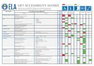
Figure 2‐3. Configuration of Geared traction lift machineroom<br />
(source: Mitsubishi)<br />
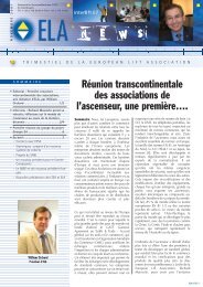
Figure 2‐4. Configuration of Gearless traction lift<br />
machine‐room (source: Mitsubishi)<br />
2.1.1 Geared <strong>Lift</strong>s<br />
Geared lifts are typically used in mid‐rise applications (7 to 20 floors) where high speed is not a<br />
major concern (typical speeds range from 0,1 m/s to 2,5 m/s). The reduction gear allows the<br />
use of smaller, less expensive motors that can thus work at higher speeds, producing the<br />
desired torque.<br />
The machine typically consists of the motor, brake, gearbox and traction sheave. The most<br />
commonly used reduction gear is still of the worm type, comprising a worm and a worm<br />
wheel. The reduction ratio of the gear is given by dividing the number of teeth on the wheel by<br />
the number of starts on the worm. These worm gears are relatively inefficient and are, in some<br />
few cases, being replaced by helical gears.<br />
2.1.2 Gearless <strong>Lift</strong>s<br />
In Gearless lifts, the sheave is driven directly by the motor, thus eliminating losses in the gear<br />
train. This type of lift has normally been used in high rise applications with nominal speeds<br />
between 2,5 m/s and 10 m/s. However, recent developments have made it available for use in<br />
low rise buildings and for speeds lower than 2,5 m/s.<br />
The machine in gearless lifts consists of a motor, traction sheave and brake. Since the motor is<br />
directly coupled to the traction sheave, there are no transmission losses and they both rotate<br />
at the same speed. The motor must, therefore, rotate at a very low speed – the rope speed is<br />
equal to the circumference of the sheave multiplied by the rotational speed of the motor. For<br />
example, for a rated speed of 5 m/s and a sheave diameter of 750 mm the required motor<br />
speed is of only 128 rpm.<br />
2.1.3 Machine Roomless <strong>Lift</strong>s<br />
Saving highly valued construction space has always been a concern for lift designers and it has<br />
been the driver of highly innovative technological solutions. Conventionally, all lifts, either<br />
9