- Page 2 and 3:
ZETOR This present operation manual
- Page 4 and 5:
CONTENTS Page Location of serial nu
- Page 6 and 7:
LOCATION OF SERIAL NUMBERS G2 5
- Page 8 and 9:
SAFETY INSTRUCTIONS FOR THE USERS P
- Page 10 and 11:
SAFETY INSTRUCTIONS FOR THE USERS P
- Page 12 and 13:
DAILY PREVENTIVE MAINTENANCE Carry
- Page 14 and 15:
DAILY PREVENTIVE MAINTENANCE FLUID
- Page 16 and 17:
DAILY PREVENTIVE MAINTENANCE SUSPEN
- Page 18 and 19:
The user of the tractor shall learn
- Page 20 and 21:
GETTING TO KNOW THE TRACTOR SAFETY
- Page 22 and 23:
GETTING TO KNOW THE TRACTOR E108 RI
- Page 24 and 25:
GETTING TO KNOW THE TRACTOR WASHER
- Page 26 and 27:
GETTING TO KNOW THE TRACTOR DRIVER
- Page 28 and 29:
GETTING TO KNOW THE TRACTOR HEATING
- Page 30 and 31:
GETTING TO KNOW THE TRACTOR E123 FA
- Page 32 and 33:
GETTING TO KNOW THE TRACTOR HEATING
- Page 34 and 35:
COCKPIT BESCHREIBUNG DER GERÄTE A
- Page 36 and 37:
DIGITAL DASHBOARD A digital dashboa
- Page 38 and 39:
GETTING TO KNOW THE TRACTOR *TILT S
- Page 40 and 41:
GETTING TO KNOW THE TRACTOR LIGHTS
- Page 42 and 43:
GETTING TO KNOW THE TRACTOR IGNITIO
- Page 44 and 45:
GETTING TO KNOW THE TRACTOR PEDALS
- Page 46 and 47:
GETTING TO KNOW THE TRACTOR P+11NH1
- Page 48 and 49:
GETTING TO KNOW THE TRACTOR TRACTOR
- Page 50 and 51: Before a drive with the new tractor
- Page 52 and 53: DRIVING BEFORE YOU START THE ENGINE
- Page 54 and 55: DRIVING G207 IMMEDIATELY AFTER STAR
- Page 56 and 57: DRIVING SHIFTING OF GEARS The tract
- Page 58 and 59: DRIVING E216 TORQUE MULTIPLIER The
- Page 60 and 61: DRIVING DIESEL PARTICLE FILTER - SY
- Page 62 and 63: DRIVING MOVING OFF 1. Tread on the
- Page 64 and 65: DRIVING DIFFERENTIAL LOCK The diffe
- Page 66 and 67: DRIVING SINGLE-HOSE AND DOUBLE-HOSE
- Page 68 and 69: DRIVING STOPPING THE TRACTOR - HAND
- Page 70 and 71: RUNNING-IN THE TRACTOR Page General
- Page 72 and 73: RUNNING-IN THE TRACTOR E256 FROM 10
- Page 74 and 75: TRANSPORT USE Page Front hook......
- Page 76 and 77: TRANSPORT USE AUTOMATIC HITCH OF TH
- Page 78 and 79: TRANSPORT USE COUPLING OF A SINGLE-
- Page 80 and 81: TRANSPORT USE MAXIMUM PERMITTED VER
- Page 82 and 83: DRIVE OF FARMING MACHINES Page Work
- Page 84 and 85: DRIVE OF FARMING MACHINES REAR OUTP
- Page 86 and 87: DRIVE OF FARMING MACHINES DRIVE OF
- Page 88 and 89: HYDRAULIC SYSTEM Page Hydraulic sys
- Page 90 and 91: HYDRAULIC SYSTEM P+11N001 HYDRAULIC
- Page 92 and 93: HYDRAULIC SYSTEM P+11N006 THREE-POI
- Page 94 and 95: HYDRAULIC SYSTEM P+11N010 POWER REG
- Page 96 and 97: HYDRAULIC SYSTEM P+11N016 EXTERIOR
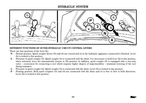
- Page 98 and 99: HYDRAULIC SYSTEM P+11N014 LOCKING C
- Page 102 and 103: HYDRAULIC SYSTEM Working area: in f
- Page 104 and 105: HYDRAULIC SYSTEM CONNECTING MACHINE
- Page 106 and 107: HITCHES Page Rear three-point hitch
- Page 108 and 109: HITCHES HEIGHT ADJUSTMENT OF LIFTIN
- Page 110 and 111: HITCHES LOWER PULL BARS WITH EXTENS
- Page 112 and 113: HITCHES P+11N021 COTROLLING FRONT T
- Page 114 and 115: CHANGE OF WHEELS TREAD Page Change
- Page 116 and 117: CHANGE OF WHEELS TREAD E502 SETTING
- Page 118 and 119: CHANGE OF WHEELS TREAD ADJUSTEMNT O
- Page 120 and 121: ADDITIONAL WEIGHTS Page Weights in
- Page 122 and 123: ADDITIONAL WEIGHTS G554 VALVE FOR F
- Page 124 and 125: ADDITIONAL WEIGHTS MAXIMUM WEIGHT O
- Page 126 and 127: ELECTRIC INSTALLATION Page Essentia
- Page 128 and 129: ELECTRIC INSTALLATION E603 BATTERY
- Page 130 and 131: ELECTRIC INSTALLATION FH12N029 FUSE
- Page 132 and 133: ELECTRIC INSTALLATION CHECK OF ADJU
- Page 134 and 135: ELECTRIC INSTALLATION LIST OF LAMPS
- Page 136 and 137: TRACTOR MAINTENANCE Page Operations
- Page 138 and 139: TRACTOR MAINTENANCE OPERATIONS CARR
- Page 140 and 141: FUELS, COOLANTS AND LUBRICANTS USED
- Page 142 and 143: TRACTOR MAINTENANCE OILS FOR TRACTO
- Page 144 and 145: TRACTOR MAINTENANCE PLASTIC LUBRICA
- Page 146 and 147: TRACTOR LUBRICATION CHART TRACTOR M
- Page 148 and 149: TRACTOR MAINTENANCE THREE-POINT SUS
- Page 150 and 151:
TRACTOR MAINTENANCE UPPER LINKAGE B
- Page 152 and 153:
TRACTOR MAINTENANCE OVERHAUL IN PRO
- Page 154 and 155:
Most of operations of planned maint
- Page 156 and 157:
MAINTENANCE INSTRUCTIONS OPENING OF
- Page 158 and 159:
MAINTENANCE INSTRUCTIONS REPLACEMEN
- Page 160 and 161:
MAINTENANCE INSTRUCTIONS INSTRUCTIO
- Page 162 and 163:
MAINTENANCE INSTRUCTIONS CHECK OF O
- Page 164 and 165:
MAINTENANCE INSTRUCTIONS REPLACEMEN
- Page 166 and 167:
MAINTENANCE INSTRUCTIONS CHECK AND
- Page 168 and 169:
MAINTENANCE INSTRUCTIONS F206 FRON
- Page 170 and 171:
MAINTENANCE INSTRUCTIONS E736 CLEAN
- Page 172 and 173:
MAINTENANCE INSTRUCTIONS WORKING PR
- Page 174 and 175:
MAINTENANCE INSTRUCTIONS GEARBOX DI
- Page 176 and 177:
ADJUSTMENTS Page Stretching of v-be
- Page 178 and 179:
ADJUSTMENTS BLEEDING OF TRACTOR BRA
- Page 180 and 181:
ADJUSTMENTS 2. BLEEDING OF BRAKES O
- Page 182 and 183:
ADJUSTMENTS 4. BLEEDING OF HYDRAULI
- Page 184 and 185:
In case that some asymmetry of brak
- Page 186 and 187:
ADJUSTMENTS E766 ADJUSTMENT OF HITC
- Page 188 and 189:
ESSENTIAL TECHNICAL PARAMETERS Page
- Page 190 and 191:
ESSENTIAL TECHNICAL PARAMETERS TECH
- Page 192 and 193:
PERMITTED MAX. LOADING OF FRONT AXL
- Page 194 and 195:
ESSENTIAL TECHNICAL PARAMETERS LOAD
- Page 196 and 197:
ESSENTIAL TECHNICAL PARAMETERS PERM
- Page 198 and 199:
FORWARD TRAVEL SPEED OF THE TRACTOR
- Page 200 and 201:
FORWARD TRAVEL SPEED OF THE TRACTOR
- Page 202 and 203:
ESSENTIAL TECHNICAL PARAMETERS SPEE
- Page 204 and 205:
A Additional weights 119 Adjustable
- Page 206 and 207:
Fuse box 129 G Gearbox distributor
- Page 208 and 209:
Overhaul in proxima tractors 151 P
- Page 210 and 211:
NOTES 209