

FLENDER Standard Couplings - DS TECH
FLENDER Standard Couplings - DS TECH
FLENDER Standard Couplings - DS TECH
- No tags were found...

Create successful ePaper yourself
Turn your PDF publications into a flip-book with our unique Google optimized e-Paper software.
© Siemens AG 2011<br />
<strong>FLENDER</strong> <strong>Standard</strong> <strong>Couplings</strong><br />
Technical Information<br />
1275 Newton, local 15<br />
Boucherville, Qc,<br />
Canada, J4B 5H2<br />
(450) 655-7447<br />
info@pt-dstech.com<br />
www.dstech.ca<br />
Balancing<br />
Because of primary shaping processes and machining, the coupling<br />
components are manufactured with a mass distribution<br />
about the axis of rotation of the motor, gear unit or driven machine<br />
which is not always ideal.<br />
Balancing means improving the mass distribution of a rotating<br />
body so that it rotates on its bearings with a sufficiently limited<br />
effect of free centrifugal forces.<br />
<br />
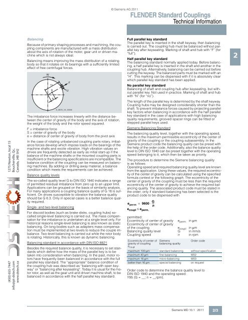
The imbalance force increases linearly with the distance between<br />
the center of gravity of the body and the axis of rotation,<br />
the weight of the body and the rotor speed squared.<br />
F = imbalance force<br />
S = center of gravity of the body<br />
e = distance of center of gravity of body from the pivot axis<br />
In the case of rotating unbalanced coupling parts rotary, imbalance<br />
forces develop which impose loads on the bearings of the<br />
machine shafts and excite vibration. High vibration values on<br />
drives are frequently detected as early as initial start-up if the<br />
balance of the machine shafts or the mounted coupling parts is<br />
insufficient or the balancing specifications are incompatible. The<br />
balance condition of the coupling can be measured on balancing<br />
machines. By adding or drilling away material, a balance<br />
condition which meets the requirements can be achieved.<br />
Balance quality levels<br />
The so-called quality level G to DIN ISO 1940 indicates a range<br />
of permitted residual imbalance from zero up to an upper limit.<br />
Applications can be grouped on the basis of similarity analysis.<br />
For many applications a coupling balance quality of G 16 is sufficient.<br />
On drives susceptible to vibration the balance quality<br />
should be G 6.3. Only in special cases is a better balance quality<br />
required.<br />
Single- and two-level balancing<br />
<br />
<br />
<br />
<br />
For discoid bodies (such as brake disks, coupling hubs) socalled<br />
single-level balancing is carried out. The mass compensation<br />
for the imbalance is undertaken at a single level only. For<br />
historical reasons single-level balancing is also known as static<br />
balancing. On long bodies such as adapters mass compensation<br />
must be implemented at two levels to reduce the couple imbalance.<br />
Two-level balancing is carried out while the rotor body<br />
is rotating. Historically, this is known as dynamic balancing.<br />
Balancing standard in accordance with DIN ISO 8821<br />
<br />
<br />
Besides the required balance quality, it is necessary to set standards<br />
which define how the mass of the parallel key is to be<br />
taken into consideration when balancing. In the past, motor rotors<br />
have frequently been balanced in accordance with the full<br />
parallel key standard. The “appropriate” balance condition of<br />
the coupling hub was described as “balancing with open keyway”<br />
or “balancing after keyseating”. Today it is usual for the motor<br />
rotor, as well as the gear unit and driven machine shaft, to be<br />
balanced in accordance with the half parallel key standard.<br />
Full parallel key standard<br />
The parallel key is inserted in the shaft keyway, then balancing<br />
is carried out. The coupling hub must be balanced without parallel<br />
key after keyseating. Marking of shaft and hub with “F” (for<br />
“full”).<br />
Half parallel key standard<br />
The balancing standard normally applied today. Before balancing,<br />
a half parallel key is inserted in the shaft and another in the<br />
coupling hub. Alternatively, balancing can be carried out before<br />
cutting the keyway. The balanced parts must be marked with an<br />
“H”. This marking can be dispensed with if it is absolutely clear<br />
which parallel key standard has been applied.<br />
No parallel key standard<br />
Balancing of shaft and coupling hub after keyseating, but without<br />
parallel key. Not used in practice. Marking of shaft and hub<br />
with “N” (for “no”).<br />
The length of the parallel key is determined by the shaft keyway.<br />
Coupling hubs may be designed considerably shorter than the<br />
shaft. To prevent imbalance forces caused by projecting parallel<br />
key factors when balancing in accordance with the half parallel<br />
key standard in the case of applications with high balancing<br />
quality requirements, grooved spacer rings can be fitted or<br />
stepped parallel keys used.<br />
Siemens Balancing <strong>Standard</strong><br />
The balancing quality level, together with the operating speed,<br />
results in the maximum permissible eccentricity of the center of<br />
gravity of the coupling or the coupling subassembly. In the<br />
Siemens product code the balancing quality can be preset with<br />
the help of the order code. Additionally, also the balance quality<br />
level to DIN ISO 1940 can be preset together with the operating<br />
speed belonging to it, which then be taken as priority.<br />
The procedure to determine the Siemens balancing quality<br />
is as follows:<br />
Operating speed and required balancing quality level are known<br />
from the application. Using these values, the required eccentricity<br />
of the center of gravity can be calculated using the specified<br />
formula context or the following graph. The eccentricity of the<br />
center of gravity of the coupling must be less than the required<br />
eccentricity of the center of gravity to achieve the required balancing<br />
quality. The associated product code must be stated in<br />
the order; only if standard balancing has been selected is the<br />
product code to be dispensed with<br />
e perm = 9600 ⋅<br />
G --- n<br />
e coupl ≤ e perm.<br />
permitted:<br />
Eccentricity of center of gravity e perm. in µm<br />
Eccentricity of center of gravity<br />
of the coupling e coupl in µm<br />
Balancing quality level G in mm/s<br />
Coupling speed n in rpm<br />
Eccentricity of center of<br />
gravity of coupling<br />
e coupl<br />
Siemens<br />
balancing quality<br />
Order code<br />
maximum 100 µm standard balancing without specification<br />
maximum 40 µm fine balancing W02<br />
maximum 16 µm micro-balancing W03<br />
better than 16 µm special balancing on request<br />
Order code to determine the balance quality level to<br />
DIN ISO 1940 and the operating speed:<br />
Y95 {G = __; n = __rpm}.<br />
2<br />
Siemens MD 10.1 · 2011<br />
2/3


