

FLENDER Standard Couplings - DS TECH
FLENDER Standard Couplings - DS TECH
FLENDER Standard Couplings - DS TECH
- No tags were found...

You also want an ePaper? Increase the reach of your titles
YUMPU automatically turns print PDFs into web optimized ePapers that Google loves.
© Siemens AG 2011<br />
<strong>FLENDER</strong> <strong>Standard</strong> <strong>Couplings</strong><br />
Flexible <strong>Couplings</strong> — RUPEX Series<br />
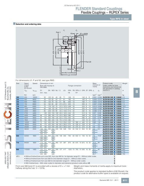
Type RFS in steel<br />
■ Selection and ordering data<br />
Part 1<br />
J1<br />
J2<br />
P<br />
U1<br />
FB<br />
ZF x ØDFB<br />
ØDA<br />
ØND1<br />
ØD1<br />
V<br />
V<br />
ØDFN<br />
ØDFK<br />
ØDFA<br />
Part 20<br />
G_MD10_EN_00097<br />
S2<br />
NL1<br />
LG<br />
S<br />
L1<br />
1275 Newton, local 15<br />
Boucherville, Qc,<br />
Canada, J4B 5H2<br />
(450) 655-7447<br />
info@pt-dstech.com<br />
www.dstech.ca<br />
For dimensions U1, P and S2, see type RWS.<br />
Size<br />
Rated<br />
torque<br />
buffer<br />
80 ShoreA<br />
Speed Dimensions in mm Mass<br />
Bore with keyway to<br />
Flange connection<br />
DIN 6885<br />
From size 560 bore D1 is provided with a recess of D = +1 mm<br />
halfway along the hub. V ≈ 1/3 NL<br />
moment of<br />
inertia<br />
Product code<br />
Order codes for bore<br />
diameters and tolerances<br />
are specified in catalog<br />
T KN n Kmax D1 DA ND1 NL1 S LG DFA FB DFN L1 DFK ZF DFB J 1 J 2 section 3<br />
m<br />
min. max. h8 H7<br />
Nm rpm kgm 2 kgm 2 kg<br />
105 200 10000 – 32 105 53 45 26 71 158 10 142 6 9 0.001 0.005 2LC0130-1AK ■ 1-0AA0 2.3<br />
125 350 9000 – 42 125 65 50 31 81 180 13 160 6 11 0.003 0.012 2LC0130-2AK ■ 1-0AA0 4.2<br />
144 500 7800 – 50 144 76 55 31 86 200 13 180 7 11 0.004 0.018 2LC0130-3AK ■ 1-0AA0 5.0<br />
162 750 6900 – 55 162 85 60 37.5 97.5 220 13 200 8 11 0.007 0.032 2LC0130-4AK ■ 1-0AA0 7.3<br />
178 950 6300 – 70 178 102 70 37.5 107.5 248 16 224 8 14 0.014 0.055 2LC0130-5AK ■ 1-0AA0 10.0<br />
198 1300 5600 – 80 198 120 80 37.5 117.5 274 16 250 8 14 0.022 0.080 2LC0130-6AK ■ 1-0AA0 13<br />
228 2200 4900 – 85 228 129 90 45.5 135.5 314 20 282 8 18 0.038 0.18 2LC0130-7AK ■ 1-0AA0 20<br />
252 2750 4400 – 100 252 150 100 45.5 145.5 344 20 312 8 18 0.07 0.26 2LC0130-8AK ■ 1-0AA0 25<br />
285 4300 3900 48 110 285 164 110 55.5 165.5 380 22 348 9 18 0.13 0.46 2LC0131-0AK ■ 1-0AA0 38<br />
320 5500 3500 55 125 320 180 125 55.5 175.5 430 25 390 9 22 0.23 0.76 2LC0131-1AK ■ 1-0AA0 50<br />
360 7800 3100 65 135 360 200 140 70.5 210.5 480 25 440 10 22 0.41 1.4 2LC0131-2AK ■ 1-0AA0 76<br />
400 12500 2800 75 150 400 230 160 74.5 234.5 520 50 380 4 480 10 22 0.92 1.8 2LC0131-3AK ■ 1-0AA0 125<br />
450 18500 2500 85 170 450 260 180 85.5 265.5 575 45 428 6 528 12 26 1.7 3.2 2LC0131-4AK ■ 1-0AA0 175<br />
500 25000 2200 95 190 500 290 200 85.5 285.5 620 45 475 6 570 12 26 2.8 4.3 2LC0131-5AK ■ 1-0AA0 210<br />
560 39000 2000 100 165 560 250 220 106 326 700 65 532 8 650 16 26 4.8 8.2 2LC0131-6AK ■ 1-0AA0 330<br />
165 200 300 5.2 2LC0131-6AK ■ 1-0AA0 340<br />
200 210 320 5.4 2LC0131-6AK ■ 1-0AA0 340<br />
630 52000 1800 100 165 630 250 240 106 346 785 60 602 8 725 16 33 7.6 13.8 2LC0131-7AK ■ 1-0AA0 390<br />
165 200 300 7.9 2LC0131-7AK ■ 1-0AA0 400<br />
200 235 355 8.7 2LC0131-7AK ■ 1-0AA0 420<br />
710 84000 1600 110 190 710 290 260 127 387 875 80 675 10 815 18 33 14.4 26 2LC0131-8AK ■ 1-0AA0 550<br />
190 220 330 14.6 2LC0131-8AK ■ 1-0AA0 560<br />
220 250 385 15.9 2LC0131-8AK ■ 1-0AA0 580<br />
800 110000 1400 125 210 800 320 290 127 417 1000 70 765 10 930 16 39 23.1 45 2LC0131-9AK ■ 1-0AA0 690<br />
210 240 360 23.3 2LC0131-9AK ■ 1-0AA0 710<br />
240 280 420 25.7 2LC0131-9AK ■ 1-0AA0 730<br />
∅D1: •Without finished bore up to size 500, from size 560 for 1st diameter range D1 – Without order codes 1<br />
•Without finished bore from size 560 for 2nd diameter range D1 – Without order codes 2<br />
•Without finished bore from size 560 for 3rd diameter range D1 – Without order codes 3<br />
•With finished bore – With order codes for diameter and tolerance (product code without -Z) 9<br />
Weight<br />
Weight and mass moments of inertia apply to maximum bore<br />
diameters.<br />
The product code applies to standard buffers of 80 ShoreA; the<br />
product code for alternative buffer types is available on request.<br />
8<br />
Siemens MD 10.1 · 2011<br />
8/11


