

FLENDER Standard Couplings - DS TECH
FLENDER Standard Couplings - DS TECH
FLENDER Standard Couplings - DS TECH
- No tags were found...

Create successful ePaper yourself
Turn your PDF publications into a flip-book with our unique Google optimized e-Paper software.
<strong>FLENDER</strong> <strong>Standard</strong> <strong>Couplings</strong><br />
Technical Information<br />
© Siemens AG 2011<br />
Shaft-hub connections<br />
2<br />
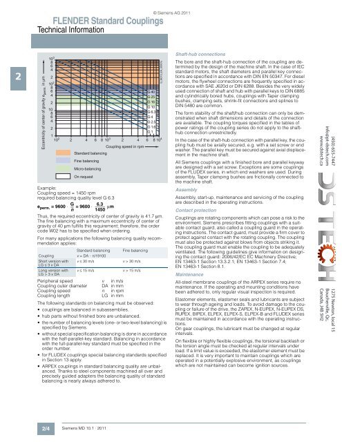
Eccentricity of center of gravity e perm. in µm<br />
10 3 8<br />
6<br />
4<br />
2<br />
10 2<br />
8<br />
6<br />
4<br />
2<br />
10<br />
8<br />
6<br />
4<br />
2<br />
1<br />
10 2 4<br />
Example:<br />
Coupling speed = 1450 rpm<br />
required balancing quality level G 6.3<br />
G 6.3<br />
e perm. = 9600 ⋅ --- = 9600 ⋅ µm<br />
n 1450<br />
Thus, the required eccentricity of center of gravity is 41.7 µm.<br />
The fine balancing with a maximum eccentricity of center of<br />
gravity of 40 µm fulfills this requirement; therefore, the order<br />
code W02 has to be specified when ordering.<br />
For many applications the following balancing quality recommendation<br />
applies:<br />
<strong>Standard</strong> balancing<br />
Coupling v =DA⋅ n/19100<br />
Short version with v ≤ 30 m/s<br />
LG ≤ 3xDA<br />
Long version with v ≤ 15 m/s<br />
LG > 3 x DA<br />
Peripheral speed v in m/s<br />
Coupling outer diameter DA in mm<br />
Coupling speed n in rpm<br />
Coupling length<br />
LG in mm<br />
Fine balancing<br />
v >30 m/s<br />
v >15 m/s<br />
G 40<br />
G 25<br />
G 16<br />
G 10<br />
G 6.3<br />
G 4<br />
G 2.5<br />
G 1.6<br />
G 1<br />
2 6 8 10 3 2 4 6 8 10 4<br />
<strong>Standard</strong> balancing<br />
Fine balancing<br />
Micro-balancing<br />
On request<br />
Coupling speed in rpm<br />
The following standards on balancing must be observed:<br />
• couplings are balanced in subassemblies.<br />
• hub parts without finished bore are unbalanced.<br />
• the number of balancing levels (one- or two-level balancing) is<br />
specified by Siemens.<br />
• without special specification balancing is done in accordance<br />
with the half-parallel-key standard. Balancing in accordance<br />
with the full-parallel-key standard must be specified in the<br />
order number.<br />
• for FLUDEX couplings special balancing standards specified<br />
in Section 13 apply.<br />
• ARPEX couplings in standard balancing quality are unbalanced.<br />
Thanks to steel components machined all over and<br />
precisely guided adapters the balancing quality of standard<br />
balancing is nearly always adhered to.<br />
G_MD10_EN_00007a<br />
The bore and the shaft-hub connection of the coupling are determined<br />
by the design of the machine shaft. In the case of IEC<br />
standard motors, the shaft diameters and parallel key connections<br />
are specified in accordance with DIN EN 50347. For diesel<br />
motors, the flywheel connections are frequently specified in accordance<br />
with SAE J620d or DIN 6288. Besides the very widely<br />
used connection of shaft and hub with parallel keys to DIN 6885<br />
and cylindrically bored hubs, couplings with Taper clamping<br />
bushes, clamping sets, shrink-fit connections and splines to<br />
DIN 5480 are common.<br />
The form stability of the shaft/hub connection can only be demonstrated<br />
when shaft dimensions and details of the connection<br />
are available. The coupling torques specified in the tables of<br />
power ratings of the coupling series do not apply to the shafthub<br />
connection unrestrictedly.<br />
In the case of the shaft-hub connection with parallel key, the coupling<br />
hub must be axially secured, e.g. with a set screw or end<br />
washer. The parallel key must be secured against axial displacement<br />
in the machine shaft.<br />
All Siemens couplings with a finished bore and parallel keyway<br />
are designed with a set screw. Exceptions are some couplings<br />
of the FLUDEX series, in which end washers are used. During<br />
assembly, Taper clamping bushes are frictionally connected to<br />
the machine shaft.<br />
Assembly<br />
Assembly, start-up, maintenance and servicing of the coupling<br />
are described in the operating instructions.<br />
Contact protection<br />
<strong>Couplings</strong> are rotating components which can pose a risk to the<br />
environment. Siemens prescribes fitting couplings with a suitable<br />
contact guard, also called a coupling guard in the operating<br />
instructions. The contact guard, must provide a firm cover to<br />
protect against contact with the rotating coupling. The coupling<br />
must also be protected against blows from objects striking it.<br />
The coupling guard must enable the coupling to be adequately<br />
ventilated. The following guidelines give information on designing<br />
the contact guard: 2006/42/EC EC Machinery Directive;<br />
EN 13463-1 Section 13.3.2.1; EN 13463-1 Section 7.4;<br />
EN 13463-1 Section 8.1.<br />
Maintenance<br />
All-steel membrane couplings of the ARPEX series require no<br />
maintenance. If the operating and mounting conditions have<br />
been adhered to, only regular visual inspection is required.<br />
Elastomer elements, elastomer seals and lubricants are subject<br />
to wear through ageing and loads. To avoid damage to the coupling<br />
or failure of the drive, the ZAPEX, N-EUPEX, N-EUPEX <strong>DS</strong>,<br />
RUPEX, BIPEX, ELPEX, ELPEX-S, ELPEX-B and FLUDEX series<br />
must be maintained in accordance with the operating instructions.<br />
On gear couplings, the lubricant must be changed at regular<br />
intervals.<br />
On flexible or highly flexible couplings, the torsional backlash or<br />
the torsion angle must be checked at regular intervals under<br />
load. If a limit value is exceeded, the elastomer element must be<br />
replaced. It is very important to maintain couplings which are<br />
operated in a potentially explosive environment, as couplings<br />
which are not maintained can become ignition sources.<br />
(450) 655-7447<br />
info@pt-dstech.com<br />
www.dstech.ca<br />
1275 Newton, local 15<br />
Boucherville, Qc,<br />
Canada, J4B 5H2<br />
2/4 Siemens MD 10.1 · 2011


