

FLENDER Standard Couplings - DS TECH
FLENDER Standard Couplings - DS TECH
FLENDER Standard Couplings - DS TECH
- No tags were found...

Create successful ePaper yourself
Turn your PDF publications into a flip-book with our unique Google optimized e-Paper software.
© Siemens AG 2011<br />
<strong>FLENDER</strong> <strong>Standard</strong> <strong>Couplings</strong><br />
Torsionally Rigid Gear <strong>Couplings</strong> — ZAPEX ZW Series<br />
Customized hub design<br />
for ZAPEX ZW Series<br />
■ Selection and ordering data<br />
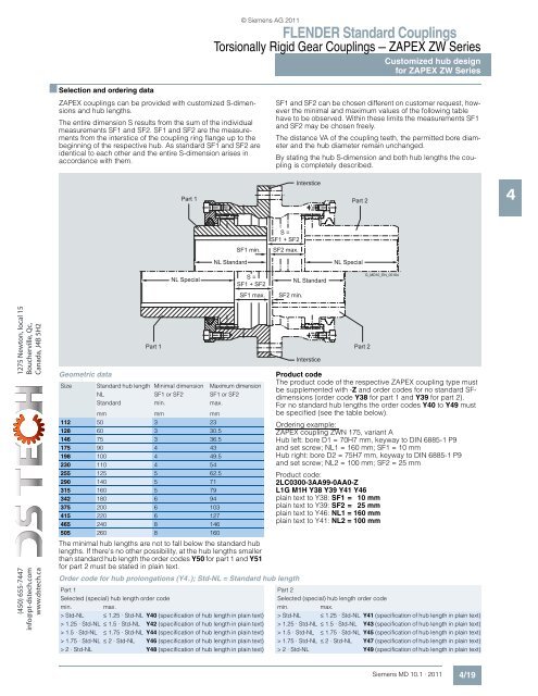
ZAPEX couplings can be provided with customized S-dimensions<br />
and hub lengths.<br />
The entire dimension S results from the sum of the individual<br />
measurements SF1 and SF2. SF1 and SF2 are the measurements<br />
from the interstice of the coupling ring flange up to the<br />
beginning of the respective hub. As standard SF1 and SF2 are<br />
identical to each other and the entire S-dimension arises in<br />
accordance with them.<br />
SF1 and SF2 can be chosen different on customer request, however<br />
the minimal and maximum values of the following table<br />
have to be observed. Within these limits the measurements SF1<br />
and SF2 may be chosen freely.<br />
The distance VA of the coupling teeth, the permitted bore diameter<br />
and the hub diameter remain unchanged.<br />
By stating the hub S-dimension and both hub lengths the coupling<br />
is completely described.<br />
Part 1<br />
Interstice<br />
Part 2<br />
4<br />
SF1 min.<br />
S =<br />
SF1 + SF2<br />
SF2 max.<br />
NL <strong>Standard</strong><br />
NL Special<br />
NL Special<br />
S =<br />
SF1 + SF2<br />
NL <strong>Standard</strong><br />
G_MD10_EN_00184<br />
SF1 max.<br />
SF2 min.<br />
1275 Newton, local 15<br />
Boucherville, Qc,<br />
Canada, J4B 5H2<br />
(450) 655-7447<br />
info@pt-dstech.com<br />
www.dstech.ca<br />
Geometric data<br />
Part 1<br />
Size <strong>Standard</strong> hub length Minimal dimension Maximum dimension<br />
NL SF1 or SF2 SF1 or SF2<br />
<strong>Standard</strong> min. max.<br />
mm mm mm<br />
112 50 3 23<br />
128 60 3 30.5<br />
146 75 3 36.5<br />
175 90 4 43<br />
198 100 4 49.5<br />
230 110 4 54<br />
255 125 5 62.5<br />
290 140 5 71<br />
315 160 5 79<br />
342 180 6 94<br />
375 200 6 103<br />
415 220 6 127<br />
465 240 8 146<br />
505 260 8 160<br />
The minimal hub lengths are not to fall below the standard hub<br />
lengths. If there's no other possibility, at the hub lengths smaller<br />
than standard hub length the order codes Y50 for part 1 and Y51<br />
for part 2 must be stated in plain text.<br />
Order code for hub prolongations (Y4.); Std-NL = <strong>Standard</strong> hub length<br />
Part 1<br />
Selected (special) hub length order code<br />
min.<br />
max.<br />
> Std-NL ≤ 1.25 · Std-NL Y40 (specification of hub length in plain text)<br />
> 1.25 · Std-NL ≤ 1.5 · Std-NL Y42 (specification of hub length in plain text)<br />
> 1.5 · Std-NL ≤ 1.75 · Std-NL Y44 (specification of hub length in plain text)<br />
> 1.75 · Std-NL ≤ 2·Std-NL Y46 (specification of hub length in plain text)<br />
> 2·Std-NL Y48 (specification of hub length in plain text)<br />
Interstice<br />
Part 2<br />
Product code<br />
The product code of the respective ZAPEX coupling type must<br />
be supplemented with -Z and order codes for no standard SFdimensions<br />
(order code Y38 for part 1 and Y39 for part 2).<br />
For no standard hub lengths the order codes Y40 to Y49 must<br />
be specified (see the table below).<br />
Ordering example:<br />
ZAPEX coupling ZWN 175, variant A<br />
Hub left: bore D1 = 70H7 mm, keyway to DIN 6885-1 P9<br />
and set screw; NL1 = 160 mm; SF1 = 10 mm<br />
Hub right: bore D2 = 75H7 mm, keyway to DIN 6885-1 P9<br />
and set screw; NL2 = 100 mm; SF2 = 25 mm<br />
Product code:<br />
2LC0300-3AA99-0AA0-Z<br />
L1G M1H Y38 Y39 Y41 Y46<br />
plain text to Y38: SF1 = 10 mm<br />
plain text to Y39: SF2 = 25 mm<br />
plain text to Y46: NL1 = 160 mm<br />
plain text to Y41: NL2 = 100 mm<br />
Part 2<br />
Selected (special) hub length order code<br />
min.<br />
max.<br />
> Std-NL ≤ 1.25 · Std-NL Y41 (specification of hub length in plain text)<br />
> 1.25 · Std-NL ≤ 1.5 · Std-NL Y43 (specification of hub length in plain text)<br />
> 1.5 · Std-NL ≤ 1.75 · Std-NL Y45 (specification of hub length in plain text)<br />
> 1.75 · Std-NL ≤ 2·Std-NL Y47 (specification of hub length in plain text)<br />
> 2·Std-NL Y49 (specification of hub length in plain text)<br />
Siemens MD 10.1 · 2011<br />
4/19


