

FLENDER Standard Couplings - DS TECH
FLENDER Standard Couplings - DS TECH
FLENDER Standard Couplings - DS TECH
- No tags were found...

Create successful ePaper yourself
Turn your PDF publications into a flip-book with our unique Google optimized e-Paper software.
3<br />
<strong>FLENDER</strong> <strong>Standard</strong> <strong>Couplings</strong><br />
Coupling Preselection and Options<br />
Product code key<br />
■ Overview<br />
The product code consists of a combination of digits and letters<br />
and is divided into three blocks linked by hyphens for better clarity.<br />
In blocks 1 and 2 the coupling series, the type and the size<br />
are encoded. Block 3 contains information applying only to the<br />
coupling specified in blocks 1 and 2. The three blocks of the<br />
product code are supplemented by information on the bore of<br />
the coupling hub parts and information on “Special types”.<br />
The bore details with the code letter L always refer to the bore<br />
diameter D1 of the hub part shown on the left on the dimension<br />
drawing. The order code beginning with M always refers to the<br />
bore diameter D2 of the hub part shown on the right on the dimension<br />
drawing.<br />
“Special types” are linked to the 3rd block of the product code<br />
by appending the code “-Z”. Special order requirements are, for<br />
example, fine balancing G6.3 or the ATEX design of the coupling.<br />
With this product code key, the couplings shown in the catalog<br />
can be completely specified. No further textual details are required,<br />
they should be avoided. <strong>Couplings</strong> in special variants<br />
are specified with the digit 9 in the 4th place in the product code<br />
(block 1) and additionally with 00-0AA0 in positions 11 to 16.<br />
Series, type and size should, as far as possible, be specified in<br />
accordance with the coding for the standard coupling. By appending<br />
“-Z Y99”, plain text information can be included. The<br />
plain text information can then clearly specify the features of the<br />
special coupling.<br />
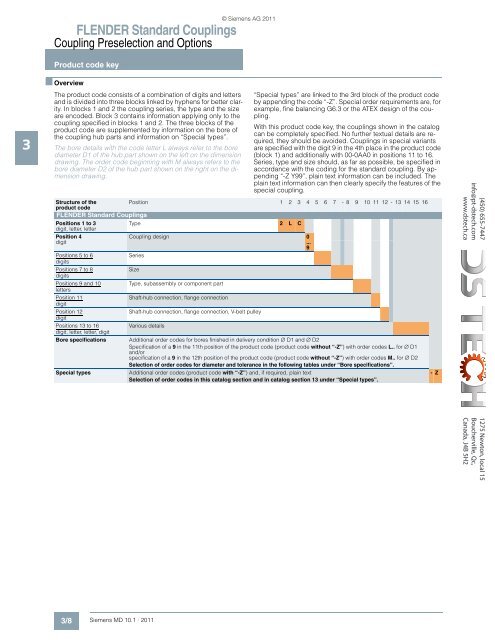
Structure of the<br />
Position 1 2 3 4 5 6 7 - 8 9 10 11 12 - 13 14 15 16<br />
product code<br />
<strong>FLENDER</strong> <strong>Standard</strong> <strong>Couplings</strong><br />
Positions 1 to 3<br />
digit, letter, letter<br />
Type 2 L C<br />
Position 4<br />
digit<br />
Positions 5 to 6<br />
digits<br />
Positions 7 to 8<br />
digits<br />
Positions 9 and 10<br />
letters<br />
Position 11<br />
digit<br />
Position 12<br />
digit<br />
Positions 13 to 16<br />
digit, letter, letter, digit<br />
Bore specifications<br />
Special types<br />
Coupling design 0<br />
...<br />
9<br />
Series<br />
Size<br />
Type, subassembly or component part<br />
Shaft-hub connection, flange connection<br />
Shaft-hub connection, flange connection, V-belt pulley<br />
Various details<br />
© Siemens AG 2011<br />
Additional order codes for bores finished in delivery condition ∅ D1 and ∅ D2<br />
Specification of a 9 in the 11th position of the product code (product code without “-Z”) with order codes L.. for ∅ D1<br />
and/or<br />
specification of a 9 in the 12th position of the product code (product code without “-Z”) with order codes M.. for ∅ D2<br />
Selection of order codes for diameter and tolerance in the following tables under “Bore specifications”.<br />
Additional order codes (product code with “-Z”) and, if required, plain text<br />
Selection of order codes in this catalog section and in catalog section 13 under “Special types”.<br />
- Z<br />
(450) 655-7447<br />
info@pt-dstech.com<br />
www.dstech.ca<br />
1275 Newton, local 15<br />
Boucherville, Qc,<br />
Canada, J4B 5H2<br />
3/8 Siemens MD 10.1 · 2011


