

FLENDER Standard Couplings - DS TECH
FLENDER Standard Couplings - DS TECH
FLENDER Standard Couplings - DS TECH
- No tags were found...

Create successful ePaper yourself
Turn your PDF publications into a flip-book with our unique Google optimized e-Paper software.
<strong>FLENDER</strong> <strong>Standard</strong> <strong>Couplings</strong><br />
Flexible <strong>Couplings</strong> — BIPEX Series<br />
General information<br />
© Siemens AG 2011<br />
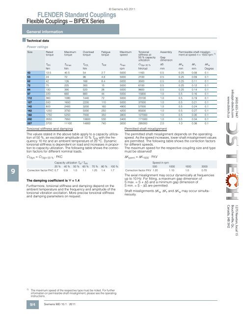
■ Technical data<br />
Power ratings<br />
Size<br />
Rated<br />
torque<br />
Maximum<br />
torque<br />
Overload<br />
torque<br />
Fatigue<br />
torque<br />
Maximum<br />
speed<br />
Torsional<br />
stiffness at<br />
50 % capacity<br />
utilization<br />
Assembly<br />
Gap<br />
dimension<br />
Permissible shaft misalignment<br />
at speed n =1500rpm 1)<br />
Torsional stiffness and damping<br />
The values stated in the above table apply to a capacity utilization<br />
of 50 %, an excitation amplitude of 10 % T KN with the frequency<br />
10 Hz and an ambient temperature of 20 °C. Dynamic<br />
torsional stiffness is dependent on load and increases in proportion<br />
to capacity utilization. The following table shows the correction<br />
factors for different nominal loads.<br />
C Tdyn = C Tdyn 50 % ⋅ FKC<br />
T KN T Kmax T KOL T KW n max C Tdyn 50 % ∆S ∆K a ∆K r ∆K w<br />
Nm Nm Nm rpm Nm/rad mm mm mm Degree<br />
43 13.5 40.5 54 2.7 5000 1160 0.5 0.25 0.08 0.1<br />
53 24 72 96 4.8 5000 2100 0.5 0.25 0.09 0.1<br />
62 42 126 168 8.4 5000 3500 0.5 0.25 0.11 0.1<br />
72 75 225 300 15 5000 6100 0.5 0.25 0.12 0.1<br />
84 130 390 520 26 5000 9600 0.5 0.25 0.14 0.1<br />
97 220 660 880 44 5000 15800 1.0 0.5 0.16 0.1<br />
112 360 1080 1440 72 5000 23100 1.0 0.5 0.19 0.1<br />
127 550 1650 2200 110 5000 37000 1.0 0.5 0.21 0.1<br />
142 800 2400 3200 160 4900 57000 1.0 0.5 0.24 0.1<br />
162 1250 3750 5000 250 4200 85000 1.0 0.5 0.27 0.1<br />
182 1750 5250 7000 350 3800 127000 1.0 0.5 0.30 0.1<br />
202 2650 7950 10600 530 3400 171000 1.0 0.5 0.34 0.1<br />
227 3700 11100 14800 740 3000 285000 2.0 1.0 0.38 0.1<br />
Permitted shaft misalignment<br />
The permitted shaft misalignment depends on the operating<br />
speed. As the speed increases, lower shaft misalignment values<br />
are permitted. The following table shows the correction factors<br />
for different speeds.<br />
The maximum speed for the respective coupling size and type<br />
must be observed!<br />
∆K perm = ∆K 1500 ⋅ FKV<br />
(450) 655-7447<br />
info@pt-dstech.com<br />
www.dstech.ca<br />
9<br />
Capacity utilization T N / T KN<br />
20 % 40 % 50 % 60 % 70 % 80 % 100 %<br />
Correction factor FKC 0.7 0.9 1.0 1.1 1.25 1.4 1.7<br />
The damping coefficient is Ψ =1.4<br />
Furthermore, torsional stiffness and damping depend on the<br />
ambient temperature and the frequency and amplitude of the<br />
torsional vibration excitation. More precise torsional stiffness<br />
and damping parameters on request.<br />
Speed in rpm<br />
500 1000 1500 3000<br />
Correction factor FKV 1.20 1.10 1.0 0.70<br />
The axial misalignment may occur dynamically at frequencies<br />
up to 10 Hz. For fitting, a maximum gap dimension of<br />
Smax.=S+∆S and a minimum gap dimension of<br />
Smin.=S–∆S are permitted.<br />
Shaft misalignments ∆K a , ∆K r and ∆K w may occur simultaneously.<br />
1275 Newton, local 15<br />
Boucherville, Qc,<br />
Canada, J4B 5H2<br />
1)<br />
The maximum speed of the respective type must be noted. For further<br />
information on permissible shaft misalignment, please see the operating<br />
instructions.<br />
9/4 Siemens MD 10.1 · 2011


