- Page 1:
ThinkPad T500 and W500 Hardware Mai
- Page 4 and 5:
Note Before using this information
- Page 6 and 7:
Locations . . . . . . . . . . . . .
- Page 8 and 9:
vi ThinkPad T500 and W500 Hardware
- Page 10 and 11:
General safety Follow these rules t
- Page 12 and 13:
v Do not touch live electrical circ
- Page 14 and 15:
Handling devices that are sensitive
- Page 16 and 17:
DANGER Before the computer is power
- Page 18 and 19:
10 ThinkPad T500 and W500 Hardware
- Page 20 and 21:
PERIGO Antes de ligar o computador
- Page 22 and 23:
DANGER Avant de remettre l’ordina
- Page 24 and 25:
VORSICHT Bevor nach einem FRU-Austa
- Page 26 and 27:
18 ThinkPad T500 and W500 Hardware
- Page 28 and 29:
20 ThinkPad T500 and W500 Hardware
- Page 30 and 31:
22 ThinkPad T500 and W500 Hardware
- Page 32 and 33:
PELIGRO Antes de encender el sistem
- Page 34 and 35:
26 ThinkPad T500 and W500 Hardware
- Page 36 and 37:
Laser compliance statement (multili
- Page 38 and 39:
Alguns modelos de computador ThinkP
- Page 40 and 41:
Einige ThinkPad-Modelle sind werkse
- Page 42 and 43:
34 ThinkPad T500 and W500 Hardware
- Page 44 and 45:
Algunos modelos de sistemas ThinkPa
- Page 46 and 47:
38 ThinkPad T500 and W500 Hardware
- Page 48 and 49:
Use the following strategy to preve
- Page 50 and 51:
v Business Partners using Eclaim wi
- Page 52 and 53:
What to do first When you do return
- Page 54 and 55:
Testing the computer Note: The PC-D
- Page 56 and 57:
v DOS Shell v Tech Support Form v B
- Page 58 and 59:
FRU tests The following table shows
- Page 60 and 61:
Power system checkout To verify a s
- Page 62 and 63:
Checking the backup battery Do the
- Page 64 and 65:
8. When the recovery process is com
- Page 66 and 67:
Note: There are two modes for the H
- Page 68 and 69:
Power management To reduce power co
- Page 70 and 71:
Symptom-to-FRU index This section c
- Page 72 and 73:
Table 2. Numeric error codes (conti
- Page 74 and 75:
Error messages Table 3. Error messa
- Page 76 and 77:
LCD-related symptoms Important: The
- Page 78 and 79:
70 ThinkPad T500 and W500 Hardware
- Page 80 and 81: Table 7. Status indicators Indicato
- Page 82 and 83: 74 ThinkPad T500 and W500 Hardware
- Page 84 and 85: Table 8. Fn key combinations (conti
- Page 86 and 87: 78 ThinkPad T500 and W500 Hardware
- Page 88 and 89: Retaining serial numbers This secti
- Page 90 and 91: 82 ThinkPad T500 and W500 Hardware
- Page 92 and 93: 1010 Battery pack Important notice
- Page 94 and 95: 1030 Hard disk drive (HDD) cover, H
- Page 96 and 97: 1040 Palm rest or palm rest with fi
- Page 98 and 99: Table 13. Installation of the palm
- Page 100 and 101: 1060 Keyboard For access, remove th
- Page 102 and 103: 1070 Modem daughter card (MDC-3.0)
- Page 104 and 105: 1080 PCI Express Mini Card for wire
- Page 106 and 107: 1090 Intel Turbo Memory Minicard or
- Page 108 and 109: 1100 Backup battery DANGER Use only
- Page 110 and 111: 1120 Keyboard bezel For access, rem
- Page 112 and 113: 1130 PCI Express Mini Card for wire
- Page 114 and 115: 1140 Speaker assembly For access, r
- Page 116 and 117: 1150 Fan assembly For access, remov
- Page 118 and 119: Table 26. Installation of the fan a
- Page 120 and 121: 1160 CPU For access, remove these F
- Page 122 and 123: Table 28. Removal steps of LCD asse
- Page 124 and 125: 1180 Base cover and USB sub card wi
- Page 126 and 127: Table 29. Removal steps of base cov
- Page 128 and 129: Note: Applying labels to the base c
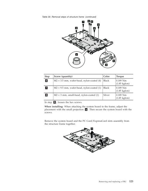
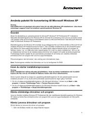
- Page 132 and 133: 1200 System board and ExpressCard s
- Page 134 and 135: Table 31. Removal steps of system b
- Page 136 and 137: Table 32. Removal steps of LCD fron
- Page 138 and 139: 2030 Inverter card or LED control c
- Page 140 and 141: 2050 Bluetooth daughter card (BDC-2
- Page 142 and 143: Table 37. Removal steps of antenna
- Page 144 and 145: 2070 LCD panel and LCD cable For ac
- Page 146 and 147: Table 38. Removal steps of LCD pane
- Page 148 and 149: 140 ThinkPad T500 and W500 Hardware
- Page 150 and 151: Rear view Bottom view ▌1▐ Statu
- Page 152 and 153: Overall 144 ThinkPad T500 and W500
- Page 154 and 155: Table 40. Parts list—Overall (con
- Page 156 and 157: Table 40. Parts list—Overall (con
- Page 158 and 159: Table 40. Parts list—Overall (con
- Page 160 and 161: Table 40. Parts list—Overall (con
- Page 162 and 163: Table 40. Parts list—Overall (con
- Page 164 and 165: Table 40. Parts list—Overall (con
- Page 166 and 167: Table 40. Parts list—Overall (con
- Page 168 and 169: Table 40. Parts list—Overall (con
- Page 170 and 171: Table 40. Parts list—Overall (con
- Page 172 and 173: Table 40. Parts list—Overall (con
- Page 174 and 175: Table 40. Parts list—Overall (con
- Page 176 and 177: Table 40. Parts list—Overall (con
- Page 178 and 179: Table 40. Parts list—Overall (con
- Page 180 and 181:
Table 40. Parts list—Overall (con
- Page 182 and 183:
Table 40. Parts list—Overall (con
- Page 184 and 185:
Table 40. Parts list—Overall (con
- Page 186 and 187:
Table 40. Parts list—Overall (con
- Page 188 and 189:
Table 40. Parts list—Overall (con
- Page 190 and 191:
Table 40. Parts list—Overall (con
- Page 192 and 193:
Table 40. Parts list—Overall (con
- Page 194 and 195:
Table 40. Parts list—Overall (con
- Page 196 and 197:
Table 40. Parts list—Overall (con
- Page 198 and 199:
Table 40. Parts list—Overall (con
- Page 200 and 201:
Table 40. Parts list—Overall (con
- Page 202 and 203:
Table 40. Parts list—Overall (con
- Page 204 and 205:
Table 40. Parts list—Overall (con
- Page 206 and 207:
Table 40. Parts list—Overall (con
- Page 208 and 209:
Table 40. Parts list—Overall (con
- Page 210 and 211:
Table 40. Parts list—Overall (con
- Page 212 and 213:
Table 40. Parts list—Overall (con
- Page 214 and 215:
Table 40. Parts list—Overall (con
- Page 216 and 217:
Table 40. Parts list—Overall (con
- Page 218 and 219:
Table 40. Parts list—Overall (con
- Page 220 and 221:
Table 40. Parts list—Overall (con
- Page 222 and 223:
Table 40. Parts list—Overall (con
- Page 224 and 225:
Table 40. Parts list—Overall (con
- Page 226 and 227:
Table 40. Parts list—Overall (con
- Page 228 and 229:
Table 41. Parts list—15.4-in. WXG
- Page 230 and 231:
Table 41. Parts list—15.4-in. WXG
- Page 232 and 233:
Table 41. Parts list—15.4-in. WXG
- Page 234 and 235:
Table 41. Parts list—15.4-in. WXG
- Page 236 and 237:
Table 41. Parts list—15.4-in. WXG
- Page 238 and 239:
Table 42. Parts list—15.4-in. WSX
- Page 240 and 241:
Table 42. Parts list—15.4-in. WSX
- Page 242 and 243:
Table 43. Parts list—15.4-in. WUX
- Page 244 and 245:
Table 43. Parts list—15.4-in. WUX
- Page 246 and 247:
Table 45. Parts list—Keyboard Lan
- Page 248 and 249:
Table 46. Parts list—Miscellaneou
- Page 250 and 251:
Power cords A ThinkPad power cord f
- Page 252 and 253:
Table 51. Parts list—Windows XP P
- Page 254 and 255:
Table 52. Parts list—Windows Vist
- Page 256 and 257:
Windows Vista Business (32 bit) DVD
- Page 258 and 259:
Windows Vista Business (64 bit) DVD
- Page 260 and 261:
Table 56. Parts list—Windows Vist
- Page 262 and 263:
Windows 7 Home Premium (32 bit) DVD
- Page 264 and 265:
Windows 7 Professional (32 bit) DVD
- Page 266 and 267:
Windows 7 Professional (64 bit) DVD
- Page 268 and 269:
260 ThinkPad T500 and W500 Hardware
- Page 270:
Trademarks vary significantly. Some