V25 Getting Started - BobCAD-CAM
V25 Getting Started - BobCAD-CAM
V25 Getting Started - BobCAD-CAM

Create successful ePaper yourself
Turn your PDF publications into a flip-book with our unique Google optimized e-Paper software.
<strong>BobCAD</strong>‐<strong>CAM</strong> Version 25 <strong>Getting</strong> <strong>Started</strong> Guide<br />
The Machine Setup Dialog Box<br />
This help topic describes using the Machine Setup dialog box of the Stock Wizard. You first select a Machine<br />
Setup, then define the machining origin of the part, as well as selecting a Work Offset, Clearance Plane, and<br />
Rotary Axis.<br />
Select the Machine Setup<br />
The Machine Setup group at the top of the dialog box lists all the Machine Setup items currently in the<br />
<strong>CAM</strong> Tree. Click the Machine Setup arrow and select the appropriate setup from the list.<br />
How to select the Machining Origin<br />
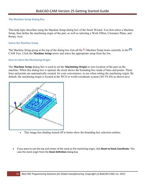
The Machine Setup dialog box is used to set the Machining Origin or zero location of the part on the<br />
machine. When this dialog box is opened, the stock shows the bounding box made of lines and points. These<br />
lines and points are automatically created, for your convenience, to use when setting the machining origin. By<br />
default, the machining origin is located at the WCS or world coordinate system (X0 Y0 Z0) as shown next.<br />
<br />
This image has shading turned off to better show the bounding box selection entities.<br />
<br />
If you want to use the top and center of the stock as the machining origin, click Reset to Stock Coordinate. This<br />
uses the stock origin from the Stock Definition dialog box.<br />
20 Real CNC Programming Solutions for Global manufacturing |Copyright (c) <strong>BobCAD</strong>‐<strong>CAM</strong>, Inc. 2012