Buderus Manual on Trenchless Installation of Ductile Cast ... - Duktus
Buderus Manual on Trenchless Installation of Ductile Cast ... - Duktus
Buderus Manual on Trenchless Installation of Ductile Cast ... - Duktus

You also want an ePaper? Increase the reach of your titles
YUMPU automatically turns print PDFs into web optimized ePapers that Google loves.
Properties <strong>of</strong> ductile cast ir<strong>on</strong> pipes<br />
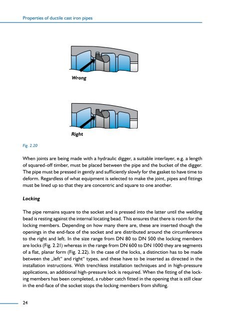
Fig. 2.20<br />
When joints are being made with a hydraulic digger, a suitable interlayer, e.g. a length<br />
<strong>of</strong> squared-<strong>of</strong>f timber, must be placed between the pipe and the bucket <strong>of</strong> the digger.<br />
The pipe must be pressed in gently and sufficiently slowly for the gasket to have time to<br />
deform. Regardless <strong>of</strong> what equipment is selected to make the joint, pipes and fittings<br />
must be lined up so that they are c<strong>on</strong>centric and square to <strong>on</strong>e another.<br />
Locking<br />
The pipe remains square to the socket and is pressed into the latter until the welding<br />
bead is resting against the internal locating bead. This ensures that there is room for the<br />
locking members. Depending <strong>on</strong> how many there are, these are inserted though the<br />
openings in the end-face <strong>of</strong> the socket and are distributed around the circumference<br />
to the right and left. In the size range from DN 80 to DN 00 the locking members<br />
are locks (Fig. 2.21) whereas in the range from DN 00 to DN 1000 they are segments<br />
<strong>of</strong> a flat, planar form (Fig. 2.22). In the case <strong>of</strong> the locks, a distincti<strong>on</strong> has to be made<br />
between the „left“ and right“ types, and these have to be inserted as directed in the<br />
installati<strong>on</strong> instructi<strong>on</strong>s. With trenchless installati<strong>on</strong> techniques and in high-pressure<br />
applicati<strong>on</strong>s, an additi<strong>on</strong>al high-pressure lock is required. When the fitting <strong>of</strong> the locking<br />
members has been completed, a rubber catch fitted in the opening that is still clear<br />
in the end-face <strong>of</strong> the socket stops the locking members from shifting.<br />
2<br />
Wr<strong>on</strong>g<br />
Right