Buderus Manual on Trenchless Installation of Ductile Cast ... - Duktus
Buderus Manual on Trenchless Installation of Ductile Cast ... - Duktus
Buderus Manual on Trenchless Installation of Ductile Cast ... - Duktus

Create successful ePaper yourself
Turn your PDF publications into a flip-book with our unique Google optimized e-Paper software.
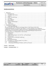
Fig. 2.21<br />
Left lock<br />
Catch<br />
Right lock<br />
High-pressure lock<br />
With nominal sizes from DN 00 to<br />
DN 1000, the planar locking segments<br />
are inserted in the axial directi<strong>on</strong> through<br />
the twin openings in the end-face <strong>of</strong> the<br />
socket and are then moved to be evenly<br />
spaced around the circumference. To<br />
simplify the locking process, the openings<br />
are preferably positi<strong>on</strong>ed to be at the<br />
crown <strong>of</strong> the pipe (Fig. 2.23). Once all the<br />
locking segments have been inserted in<br />
the gap in the socket, they are shifted as<br />
a whole around the circumference sufficiently<br />
far for n<strong>on</strong>e <strong>of</strong> the humps to be visible<br />
through the openings in the socket.<br />
The segments are fixed by a clamping strap<br />
and locked by gently pulling the pipe out <strong>of</strong><br />
the joint until the welding bead comes to<br />
rest against the segments. An extra-str<strong>on</strong>g<br />
metal clamping strap has proved useful<br />
in directi<strong>on</strong>al drilling projects involving a<br />
number <strong>of</strong> changes <strong>of</strong> directi<strong>on</strong> (Fig. 2.2 )<br />
A detailed descripti<strong>on</strong> <strong>of</strong> how the various<br />
comp<strong>on</strong>ents are dealt with and used<br />
can be found in the operating instructi<strong>on</strong>s<br />
(secti<strong>on</strong> 11).<br />
Making the BLS ® joint<br />
Fig. 2.22<br />
Fig. 2.23<br />
Fig 2.24<br />
2