Buderus Manual on Trenchless Installation of Ductile Cast ... - Duktus
Buderus Manual on Trenchless Installation of Ductile Cast ... - Duktus
Buderus Manual on Trenchless Installation of Ductile Cast ... - Duktus

Create successful ePaper yourself
Turn your PDF publications into a flip-book with our unique Google optimized e-Paper software.
The rocket plough technique<br />
6. Installing ductile cast ir<strong>on</strong> pipes by the<br />
rocket plough technique<br />
6.1 General<br />
For quite some time now, it has been the practice in rural areas for cables and plastic<br />
pipelines to be ploughed in from a drum provided there was no existing infrastructure<br />
or other obstacles al<strong>on</strong>g the path <strong>of</strong> the run. Where this is preferably d<strong>on</strong>e is al<strong>on</strong>g<br />
farm roads at the edges <strong>of</strong> areas used for agricultural purposes. The technique was<br />
successfully tried out for the first time using ductile cast ir<strong>on</strong> pipes in 2000, as part <strong>of</strong><br />
a research project, and it has now developed into a standard technique which has now<br />
been covered in the sets <strong>of</strong> rules issued by the DVGW and DWA. What is used for the<br />
installati<strong>on</strong> <strong>of</strong> ductile cast ir<strong>on</strong> pipes is the trailing plough procedure detailed in ATV<br />
DVWK Merkblatt M 1 0 [ .1] and DVGW Arbeitsblatt GW 32 (draft <strong>of</strong> /0 ) [ .2].<br />
6.2 A descripti<strong>on</strong> <strong>of</strong> the technique<br />
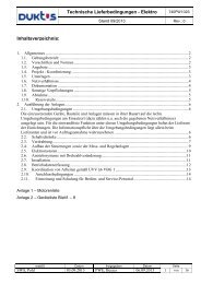
A cavity is produced by a widening body shaped like the nose <strong>of</strong> a rocket at the bottom<br />
end <strong>of</strong> a ploughshare. A pipe string, which is attached to the widening body, is pulled<br />
into this cavity in the same stage <strong>of</strong> the operati<strong>on</strong>. Fig. .1 shows the principle <strong>of</strong> the<br />
technique. So far it has been used with pipes <strong>of</strong> nominal sizes from DN 80 to DN 300.<br />
The machinery required c<strong>on</strong>sists <strong>of</strong> the tracti<strong>on</strong> vehicle (Fig. .2) and a plough (Fig. .3)<br />
carrying a ploughshare. To ensure that the vertical positi<strong>on</strong> <strong>of</strong> the path followed by the<br />
run remains c<strong>on</strong>stant when the pr<strong>of</strong>ile <strong>of</strong> the terrain varies, the depth <strong>of</strong> penetrati<strong>on</strong> <strong>of</strong><br />
the share can be c<strong>on</strong>trolled hydraulically.<br />
Fig. 6.1 The rocket plough technique<br />
8<br />
Launch<br />
pit<br />
Pipe string with<br />
tracti<strong>on</strong>-resistant joints<br />
Warning strip<br />
Widening<br />
body<br />
Ploughshare<br />
Rocket plough Tracti<strong>on</strong> vehicle<br />
Pilling<br />
rope<br />
Winch<br />
Support<br />
plate