Buderus Manual on Trenchless Installation of Ductile Cast ... - Duktus
Buderus Manual on Trenchless Installation of Ductile Cast ... - Duktus
Buderus Manual on Trenchless Installation of Ductile Cast ... - Duktus

Create successful ePaper yourself
Turn your PDF publications into a flip-book with our unique Google optimized e-Paper software.
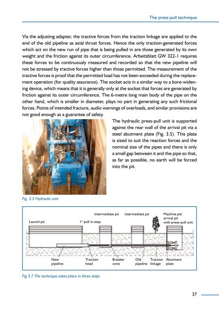
Fig. 3.5 Hydraulic unit<br />
The press-pull technique<br />
Via the adjusting adapter, the tractive forces from the tracti<strong>on</strong> linkage are applied to the<br />
end <strong>of</strong> the old pipeline as axial thrust forces. Hence the <strong>on</strong>ly tracti<strong>on</strong>-generated forces<br />
which act <strong>on</strong> the new run <strong>of</strong> pipe that is being pulled in are those generated by its own<br />
weight and the fricti<strong>on</strong> against its outer circumference. Arbeitsblatt GW 322-1 requires<br />
these forces to be c<strong>on</strong>tinuously measured and recorded so that the new pipeline will<br />
not be stressed by tractive forces higher than those permitted. The measurement <strong>of</strong> the<br />
tractive forces is pro<strong>of</strong> that the permitted load has not been exceeded during the replacement<br />
operati<strong>on</strong> (for quality assurance). The socket acts in a similar way to a bore-widening<br />
device, which means that it is generally <strong>on</strong>ly at the socket that forces are generated by<br />
fricti<strong>on</strong> against its outer circumference. The -metre l<strong>on</strong>g main body <strong>of</strong> the pipe <strong>on</strong> the<br />
other hand, which is smaller in diameter, plays no part in generating any such fricti<strong>on</strong>al<br />
forces. Points <strong>of</strong> intended fracture, audio warnings <strong>of</strong> overloads, and similar provisi<strong>on</strong>s are<br />
not good enough as a guarantee <strong>of</strong> safety.<br />
The hydraulic press-pull unit is supported<br />
against the rear wall <strong>of</strong> the arrival pit via a<br />
steel abutment plate (Fig. 3. ). This plate<br />
is sized to suit the reacti<strong>on</strong> forces and the<br />
nominal size <strong>of</strong> the pipes and there is <strong>on</strong>ly<br />
a small gap between it and the pipe so that,<br />
as far as possible, no earth will be forced<br />
into the pit.<br />
Launch pit 1st intermediate pit intermediate pit Machine pit/<br />
arrival pit<br />
pull-in step<br />
with press-pull unit<br />
New<br />
pipeline<br />
Tracti<strong>on</strong><br />
head<br />
Fig 3.7 The technique takes place in three steps<br />
Breaker<br />
c<strong>on</strong>e<br />
Old<br />
pipeline<br />
Tracti<strong>on</strong><br />
linkage<br />
Abutment<br />
plate<br />
37