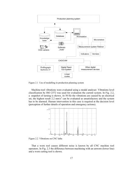
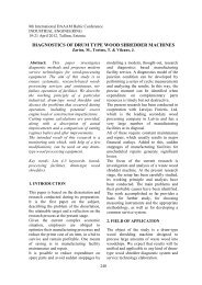
2. MODELS FOR MONITORING TECHNOLOGICAL PROCESSES2.1. Process Modell<strong>in</strong>g <strong>in</strong> Mach<strong>in</strong><strong>in</strong>g UnitTechnologically, mach<strong>in</strong><strong>in</strong>g as a process has made a significant progress. However,lack of suitable cutt<strong>in</strong>g models is a ma<strong>in</strong> bottleneck <strong>in</strong> develop<strong>in</strong>g of mach<strong>in</strong>e toolsus<strong>in</strong>g adaptive control. It is rather difficult to predict vibration, tool wear andbreakage, thermal de<strong>format</strong>ion of the mach<strong>in</strong>e tools, and similar processes based onevents us<strong>in</strong>g off-l<strong>in</strong>e theoretical models (Alt<strong>in</strong>tas, 1999). Drawbacks of the prior artmodels are unsuitability for complex cutt<strong>in</strong>g path with chang<strong>in</strong>g diameter (e.g.stepp<strong>in</strong>g shafts) and complex cutt<strong>in</strong>g contour.In turn<strong>in</strong>g operations, tool vibrations <strong>in</strong>fluence both product quality andproductivity and may also have a negative <strong>in</strong>fluence on the work<strong>in</strong>g environment(Hakansson, 1999). The effect of lathe vibration on the roughness of mach<strong>in</strong>edsurface is considered <strong>in</strong> this work. Dynamical phenomena concerned with thevibration are caused from external factors on the stra<strong>in</strong>ed system of the lathe.Dur<strong>in</strong>g the mach<strong>in</strong><strong>in</strong>g of material all disturbances f<strong>in</strong>ally lead to relativedisplacements of the cutter and the blank. It allows to l<strong>in</strong>k parameters of the surfaceroughness with the relative vibrodisplacements of the cutter and the blank(Gaponk<strong>in</strong>, 1995).Integration of different sensors and measur<strong>in</strong>g <strong>in</strong>struments <strong>in</strong>to a uniform systemis a problem of the modern technological mach<strong>in</strong>ery (Russo, 1999). Data collectedby contact and non-contact measur<strong>in</strong>g means should be managed <strong>in</strong> one system.Solutions capable of data m<strong>in</strong><strong>in</strong>g can be achieved, <strong>in</strong> theory, by SOM (Self-Oriented Maps) programme, for example <strong>in</strong> MatLab software environment(Vesanto, 2002). By stimulat<strong>in</strong>g cooperation between different manufacturers andresearch laboratories, synergies can be achieved to realise the abovementioned ma<strong>in</strong>criteria successfully. However, achievement of this goal could become veryexpensive; therefore network<strong>in</strong>g and cooperation are remarkable resources of acompany on the way to become more efficient (Riives, 2002). To solve thisproblem the idea about real time web based advisory system was <strong>in</strong>itiated. The user<strong>in</strong>teracts with the control module, the role of which is to work out the searchstrategy on the basis of <strong>in</strong>itial data given by user, via user’s <strong>in</strong>terface (Papstel,1999). As a result, a knowledge supply cha<strong>in</strong> is created.Tool wear as one of the important factors <strong>in</strong> mach<strong>in</strong><strong>in</strong>g has been <strong>in</strong>vestigated byus<strong>in</strong>g different methods. Indirect methods <strong>in</strong>volve noise recognition with amicrophone, cutt<strong>in</strong>g temperature monitor<strong>in</strong>g with thermocouples, vibrationsmeasurement (speed or acceleration) with a modal analyser, surface roughnessmeasurement with a profilograph, work piece dimension changes measurement withgauges. Direct methods <strong>in</strong>clude tool wear monitor<strong>in</strong>g with CCD cameras. Everymethod suffers from some drawback; however, comb<strong>in</strong>ed monitor<strong>in</strong>g could be asolution. In Fig. 2.1 a monitor<strong>in</strong>g system cover<strong>in</strong>g all the aforementioned devicesfor tool condition monitor<strong>in</strong>g is proposed.16
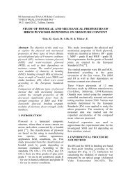
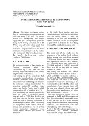
Figure 2.1 Use of modell<strong>in</strong>g <strong>in</strong> production plann<strong>in</strong>g systemMach<strong>in</strong>e-tool vibrations were evaluated us<strong>in</strong>g a modal analyser. Vibrations levelclassification by ISO 2372 was used for evaluation the current system. In Fig. 2.2,a snapshot of turn<strong>in</strong>g is shown. At 50 Hz the vibrations are caused by an electricalset, the highest result 2.2 mm/s 2 can be evaluated as unsatisfactory and the systemhas to be alarmed. Human <strong>in</strong>tervention <strong>in</strong> this case is required at the decision level(perception of further details of operation and emergency actions).Figure 2.2 Vibrations on CNC latheThat a worn tool causes different noise is known by all CNC mach<strong>in</strong>e tooloperators. In Fig. 2.3 the difference between mach<strong>in</strong><strong>in</strong>g with an unworn (lower l<strong>in</strong>e)and a worn cutt<strong>in</strong>g tool is shown.17
- Page 1 and 2: THESIS ON MECHANICAL AND INSTRUMENT
- Page 3 and 4: MASINA- JA APARAADIEHITUS E283
- Page 5 and 6: PREFACEThe mankind of the 21 st cen
- Page 7 and 8: Paper I............................
- Page 9 and 10: XII. Riives, J., Papstel, J., Otto,
- Page 11 and 12: 1. INTRODUCTION1.1. BackgroundManuf
- Page 13 and 14: database by a query; c. Search of t
- Page 15: Porter’s Diamond Model task an on
- Page 19 and 20: However, it should be noticed that
- Page 21 and 22: Figure 2.6 Depth of field/magnifica
- Page 23 and 24: 2.3. Prediction of machining accura
- Page 25 and 26: uFy=ybsinptyOl 1ulFAϕFigure 2.10 C
- Page 27 and 28: is2.5. Dynamical model with two deg
- Page 29 and 30: According to de Moivre’s formulaw
- Page 31 and 32: constant of the lathe. Figure 2.11
- Page 33 and 34: Analogically, test results and resu
- Page 35 and 36: Figure 3.1 Model checking in an ope
- Page 37 and 38: Figure 3.3 A snapshot of Uppaal mod
- Page 39 and 40: Figure 3.5 FMS at TUTM9M8M4M1M2M7M5
- Page 41 and 42: Turning and milling operations can
- Page 43 and 44: 4. MODELS FOR MONITORING THE RESOUR
- Page 45 and 46: As assumptions to solve the queries
- Page 47 and 48: Regarding co-operation networks the
- Page 49 and 50: • The system offers dynamic and u
- Page 51 and 52: Figure 4.5 Associations in the Inno
- Page 53 and 54: An enterprise-centred mapping and a
- Page 55 and 56: Better efficiency and transparency
- Page 57 and 58: institutions: in enterprises of div
- Page 59 and 60: 1. Tehnoloogiaseadme tasemel on loo
- Page 61 and 62: REFERENCESAltintas, Y. (2000). Manu
- Page 63 and 64: Russo, M.F. (1999). Automating Scie
- Page 65 and 66: Paper IIAryassov, G., Otto, T., Gro
- Page 67 and 68:
Paper IVOtto, T., Papstel, J., Riiv
- Page 69 and 70:
ELULOOKIRJELDUS (CV)1. IsikuandmedE
- Page 71 and 72:
CURRICULUM VITAE (CV)1. Personal da
- Page 73 and 74:
DISSERTATIONS DEFENDED ATTALLINN UN