Overview in PDF format - Tallinna Tehnikaülikool
Overview in PDF format - Tallinna Tehnikaülikool
Overview in PDF format - Tallinna Tehnikaülikool

You also want an ePaper? Increase the reach of your titles
YUMPU automatically turns print PDFs into web optimized ePapers that Google loves.
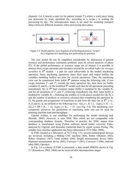
channels. Let S i denote a state (<strong>in</strong> the pattern <strong>in</strong>stant T r k) where a work piece be<strong>in</strong>gjust processed by some operation Op l accord<strong>in</strong>g to a recipe j is wait<strong>in</strong>g forprocess<strong>in</strong>g by Op i . The <strong>in</strong>teroperation states S i are used for model<strong>in</strong>g transportdelays between different locations where process<strong>in</strong>g takes place.(a)(b)Figure 3.4 Model patterns: (a) a fragment of technological process “recipe”;(b) a fragment of a mach<strong>in</strong><strong>in</strong>g unit perform<strong>in</strong>g an operationThe root model M 0 can be simplified considerably by abstraction if generalresource and performance estimation problems must be solved (analysis of phaseP2). If the global performance or resource usage are of <strong>in</strong>terest it is possible toabstract from recipe automata and <strong>in</strong>troduce <strong>in</strong>stead the so-called buffer (or storage)variables to T m models – a pair for each (observable <strong>in</strong> the model) mach<strong>in</strong><strong>in</strong>goperation. S<strong>in</strong>ce mach<strong>in</strong><strong>in</strong>g operations share their <strong>in</strong>put and output buffers thevariables model<strong>in</strong>g buffers are jo<strong>in</strong>t for several operations. Thus, the mach<strong>in</strong><strong>in</strong>gview can be constructed from <strong>in</strong>itial T m patterns us<strong>in</strong>g the follow<strong>in</strong>g rule: if tworecipe automata T r 1 and T r 2 <strong>in</strong>clude the same operation Op i , then there are buffervariables R i and R i+1 <strong>in</strong> the modified T m model such that for all operations preced<strong>in</strong>gimmediately Op i <strong>in</strong> T m their common output buffer is modeled by the variable R i ,and for all operations of T r 1 and T r 2 follow<strong>in</strong>g immediately Op i their <strong>in</strong>put buffer ismodeled by variable R i+1 . Denot<strong>in</strong>g the number of work-pieces needed for Op i by I iand the number of products or resources released after complet<strong>in</strong>g the operation byO i , the guards and assignments of transitions to and from the state Op i <strong>in</strong> T m* ( i.e.,t(.,i) and t(i,.)), are def<strong>in</strong>ed <strong>in</strong> the follow<strong>in</strong>g way: G(t xi ) ≡ R i ≥ I i , Asg(t xi ) ≡ R i – I i ;G(t ix ) ≡ RR ≥ R i+1 + O i , Asg(t ix ) ≡ R i+1 + O i (see Fig. 3.4). The mach<strong>in</strong><strong>in</strong>g viewcompletely preserves the parallelism of mach<strong>in</strong><strong>in</strong>g units and can be used forplann<strong>in</strong>g mach<strong>in</strong>e load and throughput.UppAal toolbox is one candidate for perform<strong>in</strong>g the model check<strong>in</strong>g task(Rennik, 2005). However, it uses XML files which are not comparable withcorrespond<strong>in</strong>g database <strong>format</strong>s. Therefore <strong>in</strong> practice the XML output fromdatabase is transformed us<strong>in</strong>g Python software based model converter F<strong>in</strong>ke,analysed by UppAal, and thereafter tranferred back by expert system Prolog. Thesuitable Java <strong>in</strong>terface application has been elaborated at TUT (Mäe, 2006).In FMS situated at a laboratory of TUT (Fig. 3.5), several technological devicesare <strong>in</strong>volved, <strong>in</strong>clud<strong>in</strong>g a Mill<strong>in</strong>g CNC mach<strong>in</strong>e (M8), Robot «Mentor» (M2),Robot «Serpent» (M7), Load module (M4), Height measurement device (M3),Diameter measurement device (M5), Conveyer 1 (M1), Conveyer 2 (M6), Indexedtable (M9), Operator.In Fig. 3.6 a scheme of FMS is presented, a data model (IDEF0) shown <strong>in</strong> Fig.3.7 (Karaulova, 2002, 2004) can be received after decomposition stages.38