Overview in PDF format - Tallinna Tehnikaülikool
Overview in PDF format - Tallinna Tehnikaülikool
Overview in PDF format - Tallinna Tehnikaülikool

You also want an ePaper? Increase the reach of your titles
YUMPU automatically turns print PDFs into web optimized ePapers that Google loves.
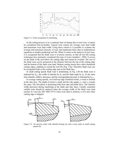
Figure 2.3 Noise recognition <strong>in</strong> mach<strong>in</strong><strong>in</strong>gAs the cutt<strong>in</strong>g process is <strong>in</strong> a cont<strong>in</strong>ual state of change due to tool wear, it cannotbe considered time-<strong>in</strong>variable. Typical wear criteria are average wear land widthand maximum wear land width. Us<strong>in</strong>g these criteria it is possible to evaluate theaverage and maximum <strong>in</strong>tensity of wear and implement these data <strong>in</strong> mathematicalequations or models predict<strong>in</strong>g tool life. When it comes to the analysis of tool wear,it is recognised that the flank wear is of prime concern, so that all tool life test<strong>in</strong>gtechniques have primarily considered this type of wear (Astakhov, 1999). It occurson the flank of the tool below the cutt<strong>in</strong>g edge and cannot be avoided. The size ofthe flank wear can be measured as the distance between the top of the cutt<strong>in</strong>g edgeand the bottom of the flank wear land. Modern cutt<strong>in</strong>g <strong>in</strong>serts have often chamferedcutt<strong>in</strong>g edges, enabl<strong>in</strong>g to extend the tool life (Fig. 2.4a). Therefore flank wear canbe recognised both on the cutt<strong>in</strong>g edge and on the flank face.At small cutt<strong>in</strong>g speeds flank wear is dom<strong>in</strong>at<strong>in</strong>g. In Fig. 2.4b the flank wear is<strong>in</strong>dicated by h αw , the width of chamfer by b γ , and the flank angle by a 0 . At the sametime chamfer width b γ decreases, and the correspond<strong>in</strong>g decrease is <strong>in</strong>dicated by b γwα .At average cutt<strong>in</strong>g speeds, over built-up edge <strong>format</strong>ion limits, a notch is formedat the rake face. The depth of notch is small and the rake angles γ o1 and γ o2 rema<strong>in</strong>the same. The first phase is shorten<strong>in</strong>g both from rake and flank faces. The chamferwidth decreases dur<strong>in</strong>g mach<strong>in</strong><strong>in</strong>g at the flank and rake faces. Usually cementedcarbide tools should be replaced when the average width of the flank wear landreaches 0.3 mm (by ISO 3685-1977) when wear land is uniform, or 0.6 mm whencutt<strong>in</strong>g edge is chipped.γo1bγγο2bγwαhαwαoFigure 2.4 An unworn cutter with chamfer hon<strong>in</strong>g (a), and a worn cutter at small cutt<strong>in</strong>gspeeds (b)18