Xilinx UG002 Virtex-II Platform FPGA User Guide
Xilinx UG002 Virtex-II Platform FPGA User Guide
Xilinx UG002 Virtex-II Platform FPGA User Guide

Create successful ePaper yourself
Turn your PDF publications into a flip-book with our unique Google optimized e-Paper software.
Product Obsolete/Under Obsolescence<strong>Virtex</strong>-<strong>II</strong><strong>Platform</strong> <strong>FPGA</strong><strong>User</strong> <strong>Guide</strong><strong>UG002</strong> (v2.2) 5 November 2007R
Product Obsolete/Under ObsolescenceR<strong>Xilinx</strong> is disclosing this user guide, manual, release note, and/or specification (the "Documentation") to you solely for use in the developmentof designs to operate with <strong>Xilinx</strong> hardware devices. You may not reproduce, distribute, republish, download, display, post, or transmit theDocumentation in any form or by any means including, but not limited to, electronic, mechanical, photocopying, recording, or otherwise,without the prior written consent of <strong>Xilinx</strong>. <strong>Xilinx</strong> expressly disclaims any liability arising out of your use of the Documentation. <strong>Xilinx</strong> reservesthe right, at its sole discretion, to change the Documentation without notice at any time. <strong>Xilinx</strong> assumes no obligation to correct any errorscontained in the Documentation, or to advise you of any corrections or updates. <strong>Xilinx</strong> expressly disclaims any liability in connection withtechnical support or assistance that may be provided to you in connection with the Information.THE DOCUMENTATION IS DISCLOSED TO YOU “AS-IS” WITH NO WARRANTY OF ANY KIND. XILINX MAKES NO OTHERWARRANTIES, WHETHER EXPRESS, IMPLIED, OR STATUTORY, REGARDING THE DOCUMENTATION, INCLUDING ANYWARRANTIES OF MERCHANTABILITY, FITNESS FOR A PARTICULAR PURPOSE, OR NONINFRINGEMENT OF THIRD-PARTYRIGHTS. IN NO EVENT WILL XILINX BE LIABLE FOR ANY CONSEQUENTIAL, INDIRECT, EXEMPLARY, SPECIAL, OR INCIDENTALDAMAGES, INCLUDING ANY LOSS OF DATA OR LOST PROFITS, ARISING FROM YOUR USE OF THE DOCUMENTATION.© 2000–2007 <strong>Xilinx</strong>, Inc. All rights reserved.XILINX, the <strong>Xilinx</strong> logo, the Brand Window, and other designated brands included herein are trademarks of <strong>Xilinx</strong>, Inc. PowerPC is atrademark of IBM, Inc. All other trademarks are the property of their respective owners.<strong>Virtex</strong>-<strong>II</strong> <strong>Platform</strong> <strong>FPGA</strong> <strong>User</strong> <strong>Guide</strong> www.xilinx.com <strong>UG002</strong> (v2.2) 5 November 2007
Product Obsolete/Under Obsolescence<strong>Virtex</strong>-<strong>II</strong> <strong>Platform</strong> <strong>FPGA</strong> <strong>User</strong> <strong>Guide</strong><strong>UG002</strong> (v2.2) 5 November 2007The following table summarizes changes made to each version of this document. Publication versions are electroniconly (PDF) unless otherwise stated.Date Version Revision12/06/00 1.0 (Printed version with data sheet modules 1-3 in Part I) Initial Release.04/02/01 1.1 Misc updates throughout.10/12/01 1.2 Misc technical edits throughout.12/03/01 1.3 (Printed version with data sheet modules 1-3 in Part I) Misc updates throughout.11/01/02 1.4 Misc updates throughout.12/02/02 1.5 Misc updates throughout.04/21/03 1.6 • Added HDL code for resetting the DCM after configuration in section "ExternalFeedback" on page 84.• Corrected Location Constraints syntax, multiple instances.• Added LVDS_25 and LVDSEXT_25 to list of I/O standards that support DCI insection "DCI in <strong>Virtex</strong>-<strong>II</strong> Hardware" on page 221.• Corrected and updated section "Using LVPECL I/O" on page 249.• Corrected command-line equivalent statements for bitstream encryption key files insection "Creating Keys" on page 253.• Added new section "Abort" on page 268 to section SelectMAP Programming Modes.• Added LVDS_25 and LVDSEXT_25 to list of I/O standards that support DCI insection "DCI in <strong>Virtex</strong>-<strong>II</strong> Hardware" on page 221.• Revised description of the JTAG output in section "Test Access Port" on page 301.• Updated configuration parameters in Table 4-12 on page 309.08/01/03 1.6.1 Table 4-3 on page 280: Corrected bias voltage on dedicated pins from 2.5V to 3.3V. Otherminor edits to this table and the text above it.02/04/04 1.7 • Figure 3-62 on page 147: Added missing connection between second LUT of Slice 3and first LUT of Slice 2.• Figure 3-74 on page 169: Corrected bit numbers on inputs to adder.• Added section "Routing with BlockRAM" on page 172.• Table 3-29 on page 176: Corrected second grouping of HSTL standards to HSTL_18.• Section "DCI I/O Buffer Library Components" on page 217, added IBUFG_LVDScomponents to list.• Section "Location Constraints" on page 237: Added constraint on locating a DDRregister next to an SDR register using a different clock.• Table 3-60 on page 238: Changed names of primitives in first row of table toIBUF_LVDS, OBUF_LVDS, etc. Underneath table, deleted text referring to primitivesused in <strong>Virtex</strong>-E and earlier designs.• Table 4-2 on page 266: Updated all configurationbitstream lengths.• Table 4-3 on page 280: Corrected directionality of BUSY/DOUT to Output, INIT_B toInput/Output.<strong>UG002</strong> (v2.2) 5 November 2007 www.xilinx.com <strong>Virtex</strong>-<strong>II</strong> <strong>Platform</strong> <strong>FPGA</strong> <strong>User</strong> <strong>Guide</strong>
Product Obsolete/Under ObsolescenceDate Version Revision02/04/04(cont’d)1.7(cont’d)• The following parameter specification tables were removed from Chapter 4,Configuration (formerly Chapter 3):- Table 3-3, Power-Up Timing Configuration Signals- Table 3-7, Master/Slave Serial Mode Programming Switching- Table 3-8, SelectMAP Write Timing Characteristics- Table 3-12, Boundary-Scan Port Timing SpecificationsSee the <strong>Virtex</strong>-<strong>II</strong> <strong>Platform</strong> <strong>FPGA</strong> Data Sheet, DC and Switching Characteristics forthese and all other parameter specifications.• Section "Mixed Voltage Environments" on page 281: Restructured with newheadings. Reworded Footnote (1) in Figure 4-4.• Added footnote to Figure 4-8 on page 286 and Figure 4-10 on page 288 clarifying thatDOUT transitions on the falling edge of CCLK.• Second paragraph below Figure 4-12 on page 292: Corrected maximumno-handshake SelectMAP configuration speed from 5 MHz to 50 MHz.• Section "Master SelectMAP Data Loading" on page 292: Changed wording toemphasize that if RDWR_B is toggled while CS_B is still asserted, a configurationabort will occur.• Section "Express-Style Loading" on page 286: Added new text to clarify thesequencing of signals before, during, and after data loading.• Section "Test Access Port" on page 301: Added mention of implementation tool pullup,pull-down, and float options on TMS and TDI pins.• Table 4-12 on page 309: Updated XC2V8000 configuration bitstream length.• Table 5-3 on page 423: Changed Theta-JC to 0.5°C/Watt for all FF packages.04/16/04 1.8 • End of Table 3-37 on page 192, added reference to XAPP689 for detailed groundbounce discussion.• Section "DCI I/O Buffer Library Components" on page 217, deletedIBUF_LVDS_33_DCI, IBUFG_LVDS_33_DCI, IBUF_LVDSEXT_33_DCI, andIBUFG_LVDSEXT_33_DCI.• Section "DCI in <strong>Virtex</strong>-<strong>II</strong> Hardware" on page 221, deleted LVDS_33_DCI andLVDSEXT_33_DCI.• Section "Using Bitstream Encryption" on page 252, added reference to Appendix C,Choosing the Battery for V BATT .• End of section "Creating Keys" on page 253, added paragraph advising use of adifferent CBC initial value for each design to insure security.• Table 4-3 on page 280, added instruction to connect V BATT to V CCAUX or GND whenbitstream encryption is not used.• Section "Frame Length Register (FLR)" on page 310, corrected definition of the valueloaded into this register by adding “minus one word.”<strong>Virtex</strong>-<strong>II</strong> <strong>Platform</strong> <strong>FPGA</strong> <strong>User</strong> <strong>Guide</strong> www.xilinx.com <strong>UG002</strong> (v2.2) 5 November 2007
Product Obsolete/Under ObsolescenceDate Version Revision08/05/04 1.9 • Revised throughout with updated tables, text, and package diagrams to include newPb-free packaging options CSG144, FGG256, FGG456, FGG676, BGG575, and BGG728.• Section "Daisy-Chain Configuration" on page 281: Revised text to clarify daisy-chainoptions for strings of different <strong>Xilinx</strong> <strong>FPGA</strong> devices.• Section "RDWR_B" on page 283: Revised text to clarify the status of the data buswhen RDWR_B is High and Low.• Table 4-14 on page 310: Corrected Footnote (1) to say “data and instruction”.03/23/05 2.0 • Chapter 4, Configuration: This chapter has been expanded and completely updatedwith new material. Since most of the material is newly written, specific changes in thischapter are not recorded in the Revision History.• Section "BUFG Exclusivity" on page 67: Corrected numbering of exclusive bufferpairs.• Figure 3-23 on page 82: Added note on when to reset the DCM.• Table 3-9 on page 105: From “Description” for CLKIN_DIVIDE_BY_2, removed textspecifying an upper frequency limit for using this attribute to divide the DCM inputclock by 2.• Section "Using Embedded Multipliers" on page 168: Deleted subsection TwoMultipliers in a Single Primitive. Deleted references to DUAL_MULT_* templates.• Table 3-29 on page 176: Added Footnote (1) for GTL and GTL+ standards. Correctedvoltage parameters for SSTL18_I and SSTL18_<strong>II</strong> standards, and added Footnote (2).• Section "Overview of Supported I/O Standards" on page 176: Added section SSTL18 -Stub Series Terminated Logic for 1.8V.• Table 3-30, Table 3-32, Table 3-34, and Table 3-35: Added symbols for SSTL18_I andSSTL18_2.• Section "Output Drive Source Voltage (V CCO ) Pins" on page 187: Added textrecommending that V CCO be powered for all I/O standards.• Table 3-36: Added entries for SSTL18_I, SSTL18_<strong>II</strong>, SSTL18_I_DCI, andSSTL18_<strong>II</strong>_DCI. Corrected parameters for HSTL_<strong>II</strong>_DCI, HSTL_I_18, HSTL_<strong>II</strong>_18,HSTL_<strong>II</strong>I_18, HSTL_IV_18, HSTL_I_DCI_18, HSTL_<strong>II</strong>_DCI_18, HSTL_<strong>II</strong>I_DCI_18,and HSTL_IV_DCI_18.• Section "DCI in <strong>Virtex</strong>-<strong>II</strong> Hardware" on page 221: Added steps 7 and 8 to list.• Added Figure 3-112 on page 228.• Code template DDR_input.v: Removed assign data_out = q1 & q2 just beforeendmodule.• Section "Using LVDS I/O" on page 243: Removed table Available <strong>Virtex</strong>-<strong>II</strong> LVDSPrimitives and associated text.• Section "Loading Encrypted Bitstreams" on page 255: Corrected reference to JTAGJSTART instruction to JTAG JPROG_B.• Added new section "Temperature-Sensing Diode (DXP/DXN)" on page 255.• Section "Design Examples" on page 487 (Appendix C): Deleted text and illustrationthat incorrectly suggested different battery voltage compliance requirements for<strong>Virtex</strong>-<strong>II</strong> and <strong>Virtex</strong>-<strong>II</strong> Pro BBRAM power pin.<strong>UG002</strong> (v2.2) 5 November 2007 www.xilinx.com <strong>Virtex</strong>-<strong>II</strong> <strong>Platform</strong> <strong>FPGA</strong> <strong>User</strong> <strong>Guide</strong>
Product Obsolete/Under ObsolescenceDate Version Revision03/28/07 2.1 • Added new section "Cascading DCMs" on page 85.• "Feedback Clock Input — CLKFB" on page 86: Added information regarding whenCLK_FEEDBACK must be set to NONE.• "Data Flow" on page 113: Added paragraph requiring block RAM address setup/holdtimes to be met if port is enabled, even if data is of no interest.• Table 3-54 (LVCMOS15) and Table 3-55 on page 208 (LVCMOS18): Updated voltagelevel definitions and values.• "DCI in <strong>Virtex</strong>-<strong>II</strong> Hardware" on page 221: Modified point 3 detailing when VRP/VRNreference resistors are not required.• "Device Startup" on page 279: Added requirement of 5-10 CCLK cycles after DONE isreleased.• Chapter 4, Configuration: Corrected various typographical errors.• Deleted section “Using XC17V00 PROMs”. Deleted section “PROM Selection <strong>Guide</strong>”and former Table 4-5, obsolete.11/05/07 2.2 • "Boundary-Scan for <strong>Virtex</strong>-<strong>II</strong> Devices Using IEEE Standard 1149.1" on page 301:Updated IEEE 1149.1 compliance statement.• Table 4-14 on page 310: Added new Step 13.• Table 4-26 on page 330: Corrected bit assignments for MATCH_CYCLE andLOCK_CYCLE.• "Configuration Memory Read Procedure (1149.1 JTAG)" on page 351: Added newsteps 5(b) and 5(c); corrected step 5(g) [formerly 5(e)].• Updated legal disclaimer.<strong>Virtex</strong>-<strong>II</strong> <strong>Platform</strong> <strong>FPGA</strong> <strong>User</strong> <strong>Guide</strong> www.xilinx.com <strong>UG002</strong> (v2.2) 5 November 2007
Product Obsolete/Under ObsolescenceContentsPreface: About This <strong>Guide</strong>Additional Resources ........................................................................................................ 15Chapter 1: Introduction to the <strong>Virtex</strong>-<strong>II</strong> <strong>FPGA</strong> Family<strong>Virtex</strong>-<strong>II</strong> <strong>Platform</strong> ............................................................................................................... 19<strong>Virtex</strong>-<strong>II</strong> Target Applications........................................................................................... 19Interconnect Engine for Fast, Wide Busses in Networking Applications............... 20Complete Solution For Rapid Time-to-Production ..................................................... 20Chapter 2: Timing ModelsSummary .............................................................................................................................. 21Introduction ............................................................................................................... 21CLB / Slice Timing Model ................................................................................................ 22Introduction ............................................................................................................... 22General Slice Timing Model and Parameters .............................................................. 22Slice Distributed RAM Timing Model and Parameters ................................................ 25Slice SRL Timing Model and Parameters .................................................................... 28Block SelectRAM Timing Model .................................................................................... 30Embedded Multiplier Timing Model ............................................................................ 34IOB Timing Model............................................................................................................. 36IOB Input Timing Model and Parameters ................................................................... 37IOB Output Timing Model and Parameters ................................................................ 41IOB 3-State Timing Model and Parameters ................................................................. 44Pin-to-Pin Timing Model.................................................................................................. 48Introduction ............................................................................................................... 48Global Clock Input to Output ..................................................................................... 49Global Clock Setup and Hold ..................................................................................... 51Digital Clock Manager Timing Model........................................................................... 53Operating Frequency Ranges ...................................................................................... 53Input Clock Tolerances ............................................................................................... 54Output Clock Precision .............................................................................................. 55Miscellaneous DCM Timing Parameters ..................................................................... 56Chapter 3: Design ConsiderationsSummary .............................................................................................................................. 59Introduction......................................................................................................................... 59Using Global Clock Networks......................................................................................... 60Introduction ............................................................................................................... 60Clock Distribution Resources ..................................................................................... 60Power Consumption .................................................................................................. 70Library Primitives and Submodules ........................................................................... 71Characteristics ............................................................................................................ 74<strong>UG002</strong> (v2.2) 5 November 2007 www.xilinx.com 7<strong>Virtex</strong>-<strong>II</strong> <strong>Platform</strong> <strong>FPGA</strong> <strong>User</strong> <strong>Guide</strong> 1-800-255-7778
Product Obsolete/Under ObsolescenceRLocation Constraints .................................................................................................. 75Secondary Clock Network .......................................................................................... 75VHDL and Verilog Instantiation ................................................................................. 75Using Digital Clock Managers (DCMs)......................................................................... 80Overview ................................................................................................................... 80Clock De-Skew ........................................................................................................... 81Frequency Synthesis ................................................................................................... 90Phase Shifting ............................................................................................................ 94DCM Waveforms ..................................................................................................... 110Using Block SelectRAM Memory ............................................................................. 113Introduction ............................................................................................................. 113Synchronous Dual-Port and Single-Port RAM .......................................................... 113Characteristics .......................................................................................................... 117Library Primitives .................................................................................................... 117VHDL and Verilog Instantiation ............................................................................... 119Port Signals .............................................................................................................. 119Address Mapping .................................................................................................... 120Attributes ................................................................................................................. 121Initialization in VHDL or Verilog Codes ................................................................... 122Location Constraints ................................................................................................ 122Applications ............................................................................................................. 123VHDL and Verilog Templates .................................................................................. 123Using Distributed SelectRAM Memory ...................................................................... 130Introduction ............................................................................................................. 130Characteristics .......................................................................................................... 131Library Primitives .................................................................................................... 132VHDL and Verilog Instantiation ............................................................................... 133Ports Signals ............................................................................................................ 133Attributes ................................................................................................................. 133Initialization in VHDL or Verilog Codes ................................................................... 134Location Constraints ................................................................................................ 134Applications ............................................................................................................. 136VHDL and Verilog Templates .................................................................................. 137Using Look-Up Tables as Shift Registers (SRLs)....................................................... 140Introduction ............................................................................................................. 140Shift Register Operations .......................................................................................... 140Characteristics .......................................................................................................... 142Library Primitives and Submodules ......................................................................... 142Initialization in VHDL and Verilog Code .................................................................. 145Port Signals .............................................................................................................. 145Attributes ................................................................................................................. 145Location Constraints ................................................................................................ 146Fully Synchronous Shift Registers ............................................................................ 147Static-Length Shift Registers ..................................................................................... 148VHDL and Verilog Instantiation ............................................................................... 149Designing Large Multiplexers ....................................................................................... 151Introduction ............................................................................................................. 151<strong>Virtex</strong>-<strong>II</strong> CLB Resources ........................................................................................... 151Wide-Input Multiplexers .......................................................................................... 155Characteristics .......................................................................................................... 155Library Primitives and Submodules ......................................................................... 1568 www.xilinx.com <strong>UG002</strong> (v2.2) 5 November 20071-800-255-7778 <strong>Virtex</strong>-<strong>II</strong> <strong>Platform</strong> <strong>FPGA</strong> <strong>User</strong> <strong>Guide</strong>
Product Obsolete/Under ObsolescenceRPort Signals .............................................................................................................. 156Applications ............................................................................................................. 157VHDL and Verilog Instantiation ............................................................................... 157Implementing Sum of Products (SOP) Logic.............................................................. 161Introduction ............................................................................................................. 161<strong>Virtex</strong>-<strong>II</strong> CLB Resources ........................................................................................... 161VHDL Parameters .................................................................................................... 162Applications ............................................................................................................. 162VHDL and Verilog Instantiation ............................................................................... 163Using Embedded Multipliers ........................................................................................ 168Introduction ............................................................................................................. 168Two’s-Complement Signed Multiplier ...................................................................... 168Library Primitives and Submodules ......................................................................... 168VHDL and Verilog Instantiation ............................................................................... 171Port Signals .............................................................................................................. 172Location Constraints ................................................................................................ 172Routing with BlockRAM .......................................................................................... 172VHDL and Verilog Templates .................................................................................. 173Using Single-Ended SelectI/O-Ultra Resources ......................................................... 175Summary ................................................................................................................. 175Introduction ............................................................................................................. 175Fundamentals .......................................................................................................... 175Overview of Supported I/O Standards ..................................................................... 176Library Symbols ....................................................................................................... 178Design Considerations ............................................................................................. 1865V Tolerance in <strong>Virtex</strong>-<strong>II</strong> Devices .............................................................................. 210Using Digitally Controlled Impedance (DCI) ............................................................ 211Introduction ............................................................................................................. 211<strong>Xilinx</strong> DCI ................................................................................................................ 211Software Support ..................................................................................................... 217DCI in <strong>Virtex</strong>-<strong>II</strong> Hardware ........................................................................................ 221Using Double-Data-Rate (DDR) I/O ............................................................................ 229Introduction ............................................................................................................. 229Data Flow ................................................................................................................ 229Characteristics .......................................................................................................... 234Library Primitives .................................................................................................... 235VHDL and Verilog Instantiation ............................................................................... 235Port Signals .............................................................................................................. 236Initialization in VHDL or Verilog ............................................................................. 237Location Constraints ................................................................................................ 237Applications ............................................................................................................. 237VHDL and Verilog Templates .................................................................................. 237Using LVDS I/O................................................................................................................ 243Introduction ............................................................................................................. 243Creating an LVDS Output Buffer .............................................................................. 244Creating an LVDS Output 3-State Buffer .................................................................. 246Creating a Bidirectional LVDS Buffer ....................................................................... 247LDT ......................................................................................................................... 248LDT Implementation ................................................................................................ 248Using LVPECL I/O ........................................................................................................... 249<strong>UG002</strong> (v2.2) 5 November 2007 www.xilinx.com 9<strong>Virtex</strong>-<strong>II</strong> <strong>Platform</strong> <strong>FPGA</strong> <strong>User</strong> <strong>Guide</strong> 1-800-255-7778
Product Obsolete/Under ObsolescenceRIntroduction ............................................................................................................. 249Creating an LVPECL Input/Clock Buffer ................................................................. 249Creating an LVPECL Output Buffer ......................................................................... 250Using Bitstream Encryption ........................................................................................... 252What DES Is ............................................................................................................. 252How Triple DES is Different ..................................................................................... 252Classification and Export Considerations ................................................................. 253Creating Keys ........................................................................................................... 253Loading Keys ........................................................................................................... 255Loading Encrypted Bitstreams .................................................................................. 255V BATT ........................................................................................................................................................ 255Temperature-Sensing Diode (DXP/DXN) ................................................................. 255Using the CORE Generator System.............................................................................. 257Introduction ............................................................................................................. 257The CORE Generator System .................................................................................... 257CORE Generator Design Flow .................................................................................. 258Core Types ............................................................................................................... 259<strong>Xilinx</strong> IP Solutions and the IP Center ........................................................................ 261CORE Generator Summary ...................................................................................... 263<strong>Virtex</strong>-<strong>II</strong> IP Cores Support ........................................................................................ 263Chapter 4: ConfigurationSummary ............................................................................................................................ 273Introduction....................................................................................................................... 273Configuration Modes ............................................................................................... 274Configuration Process and Flow ............................................................................... 276Configuration Pins ................................................................................................... 280Mixed Voltage Environments ................................................................................... 281Configuration Solutions ................................................................................................. 282Configuration PROMs .............................................................................................. 282Flash PROMs With a CPLD Configuration Controller ............................................... 283Embedded Solutions ................................................................................................ 284Software Support and Data Files .................................................................................. 285iMPACT Software .................................................................................................... 285Programming Cables ................................................................................................ 285Boundary Scan Interconnect Testing for <strong>Virtex</strong>-<strong>II</strong> Devices ......................................... 285In-System Programming Data Files .......................................................................... 285Serial Programming Modes............................................................................................ 286Master Serial Mode .................................................................................................. 286Slave Serial Mode ..................................................................................................... 287SelectMAP Programming Modes.................................................................................. 289Master SelectMAP Mode .......................................................................................... 291Slave SelectMAP Mode ............................................................................................ 292SelectMAP ABORT Sequence and ABORT Recovery.............................................. 297Triggering an ABORT .............................................................................................. 297ABORT Status Word ................................................................................................ 298ABORT Recovery ..................................................................................................... 299Internal Configuration Access Port (ICAP)................................................................. 30010 www.xilinx.com <strong>UG002</strong> (v2.2) 5 November 20071-800-255-7778 <strong>Virtex</strong>-<strong>II</strong> <strong>Platform</strong> <strong>FPGA</strong> <strong>User</strong> <strong>Guide</strong>
Product Obsolete/Under ObsolescenceRJTAG / Boundary Scan Programming Mode............................................................... 301Introduction ............................................................................................................. 301Boundary-Scan for <strong>Virtex</strong>-<strong>II</strong> Devices Using IEEE Standard 1149.1 ............................. 301Using Boundary Scan in <strong>Virtex</strong>-<strong>II</strong> Devices ................................................................ 308Boundary-Scan for <strong>Virtex</strong>-<strong>II</strong> Devices Using IEEE Standard 1532 ............................... 313Configuration Flows Using JTAG ............................................................................. 315Configuration Details...................................................................................................... 317Configuration Memory: Columns and Frames .......................................................... 317Configuration Memory Addressing .......................................................................... 319Bitstream Packets ..................................................................................................... 320Configuration Control Logic ..................................................................................... 321Configuration ........................................................................................................... 334Partial Reconfiguration ............................................................................................. 339Readback............................................................................................................................ 344Preparing a Design for Readback .............................................................................. 345Readback Command Sequences ............................................................................... 345Readback Files ......................................................................................................... 356Verifying Readback Data .......................................................................................... 356Readback Capture .................................................................................................... 359Using ChipScope ILA ............................................................................................... 360Chapter 5: PCB Design ConsiderationsSummary ............................................................................................................................ 361Pinout Information .......................................................................................................... 362Introduction ............................................................................................................. 362Pin Definitions ......................................................................................................... 362FG256 Fine-Pitch BGA Package ................................................................................ 364Pinout Diagrams............................................................................................................... 371CS144 Chip-Scale BGA Composite Pinout Diagram (XC2V250) ................................ 372FG256 Fine-Pitch BGA Composite Pinout Diagram (XC2V1000) ............................... 373FG456 Fine-Pitch BGA Composite Pinout Diagram (XC2V1000) ............................... 377FG676 Fine-Pitch BGA Composite Pinout Diagram (XC2V3000) ............................... 381BG575 Standard BGA Composite Pinout Diagram (XC2V2000) ................................. 385BG728 Standard BGA Composite Pinout Diagram (XC2V3000) ................................. 389FF896 Flip-Chip Fine-Pitch BGA Composite Pinout Diagram (XC2V2000) ................ 393FF1152 Flip-Chip Fine-Pitch BGA Composite Pinout Diagram (XC2V8000) ............... 397FF1517 Flip-Chip Fine-Pitch BGA Composite Pinout Diagram (XC2V8000) ............... 401BF957 Flip-Chip BGA Composite Pinout Diagram (XC2V6000) ................................. 405FG456 - FG676 Pinout Compatibility Diagram .......................................................... 408FF896 - FF1152 Pinout Compatibility Diagram .......................................................... 409Package Specifications .................................................................................................... 411CS144 Chip-Scale BGA Package (0.80 mm Pitch) ....................................................... 412FG256 Fine-Pitch BGA Package (1.00 mm Pitch) ....................................................... 413FG456 Fine-Pitch BGA Package (1.00 mm Pitch) ....................................................... 414FG676 Fine-Pitch BGA Package (1.00 mm Pitch) ....................................................... 415BG575 Standard BGA Package (1.27 mm Pitch) ......................................................... 416BG728 Standard BGA Package (1.27 mm Pitch) ......................................................... 417FF896 Flip-Chip Fine-Pitch BGA Package (1.00 mm Pitch) ........................................ 418FF1152 Flip-Chip Fine-Pitch BGA Package (1.00 mm Pitch) ....................................... 419FF1517 Flip-Chip Fine-Pitch BGA Package (1.00 mm Pitch) ....................................... 420<strong>UG002</strong> (v2.2) 5 November 2007 www.xilinx.com 11<strong>Virtex</strong>-<strong>II</strong> <strong>Platform</strong> <strong>FPGA</strong> <strong>User</strong> <strong>Guide</strong> 1-800-255-7778
Product Obsolete/Under ObsolescenceRBF957 Flip-Chip BGA Package (1.27 mm Pitch) ......................................................... 421Flip-Chip Packages .......................................................................................................... 422Advantages of Flip-Chip Technology ....................................................................... 422Thermal Data..................................................................................................................... 423Thermal Considerations ........................................................................................... 423Thermal Management Options ................................................................................. 424Printed Circuit Board Considerations .......................................................................... 425Layout Considerations ............................................................................................. 425V CC Decoupling ....................................................................................................... 425Board Routability <strong>Guide</strong>lines........................................................................................ 430Board-Level BGA Routing Challenges ...................................................................... 430Board Routing Strategy ............................................................................................ 431Power Consumption ........................................................................................................ 452CLB Logic Power ..................................................................................................... 452Block SelectRAM Power ........................................................................................... 455Digital Clock Management Power ............................................................................ 456Non-Registered Multiplier Power ............................................................................. 456Registered Multiplier Power ..................................................................................... 457Input/Output Power ................................................................................................ 457Results ..................................................................................................................... 458IBIS Models....................................................................................................................... 460Using IBIS Models .................................................................................................... 460IBIS Generation ........................................................................................................ 460Advantages of IBIS ................................................................................................... 460IBIS File Structure .................................................................................................... 461IBIS I/V and dV/dt Curves ...................................................................................... 461Ramp and dV/dt Curves .......................................................................................... 462IBIS Simulations ....................................................................................................... 462IBIS Simulators ......................................................................................................... 464<strong>Xilinx</strong> IBIS Advantages ............................................................................................. 464IBIS Reference Web Site ............................................................................................ 464BSDL and Boundary Scan Models................................................................................ 465BSDL Files ................................................................................................................ 465Appendix A: BitGen and PROMGen Switches and OptionsUsing BitGen..................................................................................................................... 467BitGen Syntax .......................................................................................................... 468BitGen Files .............................................................................................................. 468BitGen Options ......................................................................................................... 469Using PROMGen.............................................................................................................. 475PROMGen Syntax .................................................................................................... 476PROMGen Files ........................................................................................................ 476PROMGen Options .................................................................................................. 477Examples ................................................................................................................. 479Appendix B: <strong>Platform</strong> Flash Family PROMsPROM Package Specifications....................................................................................... 481FS48 Package Specification ....................................................................................... 48212 www.xilinx.com <strong>UG002</strong> (v2.2) 5 November 20071-800-255-7778 <strong>Virtex</strong>-<strong>II</strong> <strong>Platform</strong> <strong>FPGA</strong> <strong>User</strong> <strong>Guide</strong>
Product Obsolete/Under ObsolescenceRVO48 Package Specification ...................................................................................... 483VO20 Package Specification ...................................................................................... 484Appendix C: Choosing the Battery for V BATTBattery Types and Chemistry Choices ......................................................................... 485Primary or Secondary ............................................................................................... 485Battery Cost and Care ............................................................................................... 486Battery Summary ..................................................................................................... 486Design Examples .............................................................................................................. 487Case #1: .................................................................................................................... 487Case #2: .................................................................................................................... 487Case #3: .................................................................................................................... 487Case #4: .................................................................................................................... 488Glossary ............................................................................................................................... 489Index ....................................................................................................................................... 499<strong>UG002</strong> (v2.2) 5 November 2007 www.xilinx.com 13<strong>Virtex</strong>-<strong>II</strong> <strong>Platform</strong> <strong>FPGA</strong> <strong>User</strong> <strong>Guide</strong> 1-800-255-7778
RProduct Obsolete/Under Obsolescence14 www.xilinx.com <strong>UG002</strong> (v2.2) 5 November 20071-800-255-7778 <strong>Virtex</strong>-<strong>II</strong> <strong>Platform</strong> <strong>FPGA</strong> <strong>User</strong> <strong>Guide</strong>
Product Obsolete/Under ObsolescenceRPrefaceAbout This <strong>Guide</strong>This document describes the function and operation of <strong>Virtex</strong>-<strong>II</strong> devices and alsoincludes information on <strong>FPGA</strong> configuration techniques and PCB design considerations.For <strong>Virtex</strong>-<strong>II</strong> device specifications, refer to the <strong>Virtex</strong>-<strong>II</strong> Data Sheet (DS031).This guide provides details on the following topics:• Chapter 1: Introduction to the <strong>Virtex</strong>-<strong>II</strong> <strong>FPGA</strong> Family• Chapter 2: Timing Models• Chapter 3: Design Considerations• Chapter 4: Configuration• Chapter 5: PCB Design Considerations• Appendix A: BitGen and PROMGen Switches and Options• Appendix B: <strong>Platform</strong> Flash Family PROMs• Appendix C: Choosing the Battery for V BATT• GlossaryAdditional ResourcesThe following table lists URLs for resources available on the web. For additionalinformation, go to http://www.xilinx.com.ResourceData Sheets<strong>User</strong> <strong>Guide</strong>sApplicationNotesXcell JournalsDescription/URL<strong>Xilinx</strong> data sheets describe device-specific operating characteristics,architecture, and pinouts/packaging.http://www.xilinx.com/xlnx/xweb/xil_publications_index.jsp<strong>Xilinx</strong> user guides contain detailed, device-specific operating theoryand generic design examples for various device functions.http://www.xilinx.com/xlnx/xweb/xil_publications_index.jsp?category=<strong>User</strong>+<strong>Guide</strong>s<strong>Xilinx</strong> application notes describe design techniques and approaches togeneral design as well as specific applications. Many application notesfeature complete reference designs including source code.http://www.xilinx.com/xlnx/xweb/xil_publications_index.jsp?category=Application+NotesThis site contains quarterly journals for <strong>Xilinx</strong> programmable logic users.http://www.xilinx.com/xcell/xcell.htm<strong>UG002</strong> (v2.2) 5 November 2007 www.xilinx.com 15<strong>Virtex</strong>-<strong>II</strong> <strong>Platform</strong> <strong>FPGA</strong> <strong>User</strong> <strong>Guide</strong>
RProduct Obsolete/Under ObsolescencePreface: About This <strong>Guide</strong>ResourceTech TipsAnswersDatabaseDescription/URLSee this site for the latest news, design tips, and patch information on the<strong>Xilinx</strong> design environment.http://www.xilinx.com/support/techsup/journals/index.htmThis database provides a current listing of solution records for <strong>Xilinx</strong>software tools. Search this database using the search function at:http://www.xilinx.com/support/searchtd.htmConventionsThis document uses the following conventions. An example illustrates each convention.TypographicalThe following typographical conventions are used in this document:Convention Meaning or Use ExampleCourier fontCourier boldHelvetica boldItalic fontSquare brackets [ ]Braces { }Vertical bar |Messages, prompts, andprogram files that the systemdisplaysLiteral commands that youenter in a syntactical statementCommands that you selectfrom a menuKeyboard shortcutsVariables in a syntaxstatement for which you mustsupply values. (In anglebrackets.)References to other manualsEmphasis in textAn optional entry orparameter. However, in busspecifications, such asbus[7:0], they are required.A list of items from which youmust choose one or moreSeparates items in a list ofchoicesspeed grade: - 100ngdbuild design_nameFile → OpenCtrl+Cngdbuild See the Development SystemReference <strong>Guide</strong> for moreinformation.If a wire is drawn so that itoverlaps the pin of a symbol,the two nets are not connected.ngdbuild [option_name]design_namelowpwr ={on|off}lowpwr ={on|off}16 www.xilinx.com <strong>UG002</strong> (v2.2) 5 November 2007<strong>Virtex</strong>-<strong>II</strong> <strong>Platform</strong> <strong>FPGA</strong> <strong>User</strong> <strong>Guide</strong>
Additional ResourcesProduct Obsolete/Under ObsolescenceRConvention Meaning or Use ExampleVertical ellipsis...Horizontal ellipsis . . .Repetitive material that hasbeen omittedRepetitive material that hasbeen omittedIOB #1: Name = QOUT’IOB #2: Name = CLKIN’...allow block block_nameloc1 loc2 ... locn;Online DocumentThe following conventions are used in this document:Convention Meaning or Use ExampleRed textBlue, underlined textCross-reference link to alocation in the currentdocumentHyperlink to a website (URL)See the section AdditionalResources for details.Refer to Title Formats,Chapter 1 for details.Go to http://www.xilinx.comfor the latest speed files.<strong>UG002</strong> (v2.2) 5 November 2007 www.xilinx.com 17<strong>Virtex</strong>-<strong>II</strong> <strong>Platform</strong> <strong>FPGA</strong> <strong>User</strong> <strong>Guide</strong>
RProduct Obsolete/Under ObsolescencePreface: About This <strong>Guide</strong>18 www.xilinx.com <strong>UG002</strong> (v2.2) 5 November 2007<strong>Virtex</strong>-<strong>II</strong> <strong>Platform</strong> <strong>FPGA</strong> <strong>User</strong> <strong>Guide</strong>
Product Obsolete/Under ObsolescenceRChapter 1Introduction to the <strong>Virtex</strong>-<strong>II</strong><strong>FPGA</strong> Family<strong>Virtex</strong>-<strong>II</strong> <strong>Platform</strong>The <strong>Virtex</strong>-<strong>II</strong> <strong>Platform</strong> <strong>FPGA</strong> solution is the result of the largest silicon and software R&Deffort in the history of programmable logic, with the goal of revolutionizing the design ofcomplex single-chip sub-systems in terms of engineering productivity, silicon efficiency,and system flexibility.The <strong>Virtex</strong>-<strong>II</strong> product family provides IP-Immersion technology which incorporates anabundance of on-chip memory options and advanced routing resources for supportingcomplex designs that use IP (intellectual property), such as on-chip hard-macro buildingblocks and a rapidly growing library of soft-IP blocks. For the first time in theprogrammable logic industry, innovative <strong>Virtex</strong>-<strong>II</strong> features enable system designers to:• Eliminate external termination resistors with on-chip precision-controlled outputimpedance• Manage 16 pre-engineered low-skew clock domains, with on-chip frequency andphase control• Protect chip designs with bit-stream encryptionThese unique capabilities increase engineering productivity and time-to-production bysupply pre-engineered solutions for signal integrity and RF noise challenges, as well asproviding a secure means to deliver designs rapidly to production.The <strong>Virtex</strong>-<strong>II</strong> <strong>Platform</strong> <strong>FPGA</strong> family is a complete programmable solution that allowsdigital system designers to rapidly implement a single-chip solution with density up to 10million system gates, in weeks rather than months or years. The inherent flexibility of<strong>Xilinx</strong> <strong>FPGA</strong> devices allows unlimited design changes throughout the development andproduction phases of the system, with important benefits in improved productivity,reduced design risk, and higher system flexibility. This further accelerates the industry --from custom ASICs to <strong>FPGA</strong>s -- in fields such as optical networking systems, gigabitrouters, wireless cellular base stations, modem arrays, and professional video broadcastsystems.<strong>Virtex</strong>-<strong>II</strong> Target ApplicationsThe <strong>Virtex</strong>-<strong>II</strong> solution is developed specifically to enable rapid development of two of themost technically challenging digital system applications: data communications and digitalsignal processing (DSP) systems. High logic integration, fast and complex routing of widebusses, and extensive pipeline and FIFO memory requirements characterize these systems.The <strong>Virtex</strong>-<strong>II</strong> family incorporates high logic capacity, up to 10 million system gates, a newActive Interconnect architecture optimized for predictable routing delays, an advanced<strong>UG002</strong> (v2.2) 5 November 2007 www.xilinx.com 19<strong>Virtex</strong>-<strong>II</strong> <strong>Platform</strong> <strong>FPGA</strong> <strong>User</strong> <strong>Guide</strong>
RProduct Obsolete/Under ObsolescenceChapter 1: Introduction to the <strong>Virtex</strong>-<strong>II</strong> <strong>FPGA</strong> Familymemory array architecture with up to 4.5Mbits of on-chip memory, and built-in supportfor high-speed I/O standards at up to 1108 user pins.Applications incorporating DSP functionality, such as echo cancellation, forward errorcorrection,and image compression/decompression, benefit from the abundance ofembedded high-speed 18-bit x 18-bit multiplier blocks within the <strong>Virtex</strong>-<strong>II</strong> solution.The unique features of the revolutionary <strong>Virtex</strong>-<strong>II</strong> architecture make it ideal for opticalnetworking products, storage area networks (SANs), Voice-over-Internet-Protocol (VoIP),video broadcasting, medical imaging, wireless base-stations, and Internet infrastructureproducts, as well as many other products.Interconnect Engine for Fast, Wide Busses in NetworkingApplicationsThe <strong>Virtex</strong>-<strong>II</strong> architecture incorporates a number of novel features specifically to supportwide data widths in complex networking and transmission systems. Modern complexsystems operate with multiple clock domains, with large IP-based subsystems operatingindependently. Large, wide FIFOs and buffer memories are needed for handling fast andwide inter-subsystem data transfer. These wide busses are required both internally forintra-chip communications and externally for switched fabric communications.For example, wide 32-bit and larger data busses can drive multiple Ultra Low-VoltageDifferential Signal (ULVDS) high-speed interface standards for data transfer across abackplane or for point-to-point communications, or be used for implementing high-speedmulti-cast bus standards.These requirements challenge and exceed the capabilities of current programmable logicdevices, which lack the gate capacity, memory and routing resources, performance, andarchitecture flexibility to fully support these designs. The <strong>Virtex</strong>-<strong>II</strong> solution is the firstplatform <strong>FPGA</strong> specifically targeted to improve the “ease of speed” in the developmentand production of these complex systems.Complete Solution For Rapid Time-to-ProductionThe <strong>Virtex</strong>-<strong>II</strong> solution combines the most flexible <strong>FPGA</strong> architecture, advanced processtechnology, powerful software synthesis technology, and robust IP library, to provide themost complete system integration solution today. In addition, the <strong>Virtex</strong>-<strong>II</strong> solutionprovides powerful features, such as <strong>Xilinx</strong> Digitally Controlled Impedance (DCI)technology, digital clock manager to help designers further reduce overall system cost anddesign development cycle, making <strong>Virtex</strong>-<strong>II</strong> the ideal solution for tomorrow’s highperformancesystem designs.20 www.xilinx.com <strong>UG002</strong> (v2.2) 5 November 2007<strong>Virtex</strong>-<strong>II</strong> <strong>Platform</strong> <strong>FPGA</strong> <strong>User</strong> <strong>Guide</strong>
Product Obsolete/Under ObsolescenceRChapter 2Timing ModelsSummaryThe following topics are covered in this chapter:• CLB / Slice Timing Model• Block SelectRAM Timing Model• Embedded Multiplier Timing Model• IOB Timing Model• Pin-to-Pin Timing Model• Digital Clock Manager Timing ModelIntroductionDue to the large size and complexity of <strong>Virtex</strong>-<strong>II</strong> <strong>FPGA</strong>s, understanding the timingassociated with the various paths and functional elements has become a difficult andimportant problem. Although it is not necessary to understand the various timingparameters in order to implement most designs using <strong>Xilinx</strong>, Inc. software, a thoroughtiming model can assist advanced users in analyzing critical paths, or planning speedsensitivedesigns.The Timing Model chapter is broken up into five sections consisting of three basiccomponents:• Functional Element Diagram - basic architectural schematic illustrating pins andconnections.• Timing Parameters - <strong>Virtex</strong>-<strong>II</strong> Data Sheet (DS031) timing parameter definitions.• Timing Diagram - illustrates functional element timing parameters relative to eachother.This chapter was written with the <strong>Xilinx</strong> Timing Analyzer software (TRCE) in mind. Allpin names, parameter names, and paths are consistent with Post Route Timing and Pre-Route Static Timing reports. Use the models in this chapter in conjunction with both theTiming Analyzer software and the section on switching characteristics in the <strong>Virtex</strong>-<strong>II</strong> DataSheet (DS031). Most of the timing parameters found in the section on switchingcharacteristics are described in this chapter.<strong>UG002</strong> (v2.2) 5 November 2007 www.xilinx.com 21<strong>Virtex</strong>-<strong>II</strong> <strong>Platform</strong> <strong>FPGA</strong> <strong>User</strong> <strong>Guide</strong>
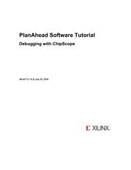
RCLB / Slice Timing ModelIntroductionProduct Obsolete/Under ObsolescenceChapter 2: Timing ModelsThe three sections below describes all timing parameters reported in the <strong>Virtex</strong>-<strong>II</strong> DataSheet that are associated with slices and Configurable Logic Blocks (CLBs). The sectionscorrespond to their respective (switching characteristics) sections in the data sheet:• General Slice Timing Model and Parameters (CLB Switching Characteristics)• Slice Distributed RAM Timing Model and Parameters (CLB Distributed RAMSwitching Characteristics)• Slice SRL Timing Model and Parameters (CLB SRL Switching Characteristics)General Slice Timing Model and ParametersFigure 2-1 illustrates the details of a <strong>Virtex</strong>-<strong>II</strong> slice.Note: Some elements of the <strong>Virtex</strong>-<strong>II</strong> slice have been omitted for clarity. Only the elementsrelevant to the timing paths described in this section are shown.FXINAFXINBMUXFXFXYDYGinputsLUTDD QFF/LATCECLKYQSRREVBYMUXF5F5XLUTFinputsDDXD QFF/LATCECLKXQSRREVBXCECLKSR<strong>UG002</strong>_C3_017_113000Figure 2-1:General Slice Diagram22 www.xilinx.com <strong>UG002</strong> (v2.2) 5 November 2007<strong>Virtex</strong>-<strong>II</strong> <strong>Platform</strong> <strong>FPGA</strong> <strong>User</strong> <strong>Guide</strong>
CLB / Slice Timing ModelProduct Obsolete/Under ObsolescenceRTiming ParametersTable 2-1:General Slice Tming ParametersParameterFunctionControlSignalDescriptionCombinatorial DelaysT ILOT IF5T IF5XT IFXYT IFNCTLF/G inputs toX/Y outputsF/G inputs to F5outputF/G inputs to XoutputFXINA/FXINBinputs to Y outputTransparent Latchinput to XQ/YQoutputsPropagation delay from the F/G inputs of theslice, through the look-up tables (LUTs), to theX/Y outputs of the slice.Propagation delay from the F/G inputs of theslice, through the LUTs and MUXF5 to the F5output of the slice.Propagation delay from the F/G inputs of theslice, through the LUTs and MUXF5 to the Xoutput of the slice.Propagation delay from the FXINA/FXINBinputs, through MUXFX to the Y output of theslice.Incremental delay through a transparent latchto XQ/YQ outputs.Sequential DelaysT CKOT CKLOFF Clock (CLK) toXQ/YQ outputsLatch Clock(CLK) to XQ/YQoutputsTime after the clock that data is stable at theXQ/YQ outputs of the slice sequentialelements (configured as a flip-flop).Time after the clock that data is stable at theXQ/YQ outputs of the slice sequentialelements (configured as a latch).Setup and Hold for Slice Sequential ElementsT xxCK = Setup time (before clock edge)T CKxx = Hold time (after clock edge)T DICK /T CKDIBX/BY inputsThe following descriptions are for setuptimes only.Time before Clock (CLK) that data from the BXor BY inputs of the slice must be stable at theD-input of the slice sequential elements(configured as a flip-flop).T DYCK /T CKDYT DXCK /T CKDXT CECK /T CKCET RCK /T CKRDY inputDX inputCE inputSR/BY inputsTime before Clock (CLK) that data from the DYinput of the slice must be stable at the D-inputof the slice sequential elements (configured asa flip-flop).Time before Clock (CLK) that data from the DXinput of the slice must be stable at the D-inputof the slice sequential elements (configured asa flip-flop).Time before Clock (CLK) that the CE (ClockEnable) input of the slice must be stable at theCE-input of the slice sequen-tial elements(configured as a flip-flop).Time before CLK that the SR (Set/Reset) andthe BY (Rev) inputs of the slice must be stableat the SR/Rev-inputs of the slice sequentialelements (configured as a flip-flop).Synchronous set/reset only.<strong>UG002</strong> (v2.2) 5 November 2007 www.xilinx.com 23<strong>Virtex</strong>-<strong>II</strong> <strong>Platform</strong> <strong>FPGA</strong> <strong>User</strong> <strong>Guide</strong>
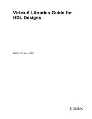
RProduct Obsolete/Under ObsolescenceChapter 2: Timing ModelsTable 2-1:General Slice Tming Parameters (Continued)ParameterFunctionControlSignalDescriptionClock CLKT CHMinimum Pulse Width, High.T CLMinimum Pulse Width, Low.Set/ResetT RPWMinimum Pulse Width for the SR (Set/Reset)and BY (Rev) pins.T RQPropagation delay for an asynchronousSet/Reset of the slice sequential elements.From SR/BY inputs to XQ/YQ outputs.F TOGToggle Frequency - Maximum Frequency thata CLB flip-flop can be clocked:1/(T CH +T CL )Timing CharacteristicsFigure 2-2 illustrates general timing characteristics of a <strong>Virtex</strong>-<strong>II</strong> slice.1 2 3CLKCEDY(DATA)SR(RESET)YQ(OUT)T CECKT DYCKT CKOT RCKT CKO<strong>UG002</strong>_C3_018_101600Figure 2-2:General Slice Timing Diagram• At time T CECK before Clock Event 1, the Clock-Enable signal becomes valid-high atthe CE input of the slice register.• At time T DYCK before Clock Event 1, data from the DY input becomes valid-high at theD input of the slice register and is reflected on the YQ pin at time T CKO after ClockEvent 1*.• At time T RCK before Clock Event 3, the SR signal (configured as synchronous reset inthis case) becomes valid-high, resetting the slice register, and this is reflected on theYQ pin at time T CKO after Clock Event 3.* NOTE: In most cases software uses the DX/DY inputs to route data to the slice registers whenat all possible. This is the fastest path to the slice registers and saves other slice routing resources.24 www.xilinx.com <strong>UG002</strong> (v2.2) 5 November 2007<strong>Virtex</strong>-<strong>II</strong> <strong>Platform</strong> <strong>FPGA</strong> <strong>User</strong> <strong>Guide</strong>
CLB / Slice Timing ModelProduct Obsolete/Under ObsolescenceSlice Distributed RAM Timing Model and ParametersFigure 2-3 illustrates the details of distributed RAM implemented in a <strong>Virtex</strong>-<strong>II</strong> slice.Note: Some elements of the <strong>Virtex</strong>-<strong>II</strong> slice have been omitted for clarity. Only the elementsrelevant to the timing paths described in this section are shown.RFXINAFXINBMUXFXFXADDRESSG4G3G2G1RAMDYBYDATA_IN orAddressWSDISLICEWE[2:0]WSGENWECKMUXF5ADDRESSG4G3G2G1WS DIRAMDF5XBXDATA_IN orAddressCLKSR(Write Enable)<strong>UG002</strong>_C3_019_1204 00Figure 2-3:Slice Distributed RAM Diagram<strong>UG002</strong> (v2.2) 5 November 2007 www.xilinx.com 25<strong>Virtex</strong>-<strong>II</strong> <strong>Platform</strong> <strong>FPGA</strong> <strong>User</strong> <strong>Guide</strong>
RProduct Obsolete/Under ObsolescenceChapter 2: Timing ModelsTiming ParametersTable 2-2:Slice Distributed RAM Timing ParametersParameterFunctionControlSignalDescriptionSequential Delays for Slice LUT Configured as RAM (Distributed RAM)T SHCKO16T SHCKO32T SHCKOF5CLK to X/Y outputs(WE active) in 16x1modeCLK to X/Y outputs(WE active) in 32x1modeCLK to F5 output (WEactive)Time after the Clock (CLK) of a WRITEoperation that the data written to thedistributed RAM (in 16x1 mode) is stable onthe X/Y outputs of the slice.Time after the Clock (CLK) of a WRITEoperation that the data written to thedistributed RAM (in 32x1 mode) is stable onthe X/Y outputs of the slice.Time after the Clock (CLK) of a WRITEoperation that the data written to thedistributed RAM is stable on the F5 output ofthe slice.Setup and Hold for Slice LUT Configured as RAM (Distributed RAM)T xS = Setup time (before clock edge)T xH = Hold time (after clock edge)T DS /T DHBX/BY Data inputs(DI)The following descriptions are for setuptimes only.Time before the clock that data must be stableat the DI input of the slice LUT (configured asRAM), via the slice BX/BY inputs.T AS /T AHT WES /T WEHClock CLKT WPHT WPLT WCF/G Address inputsWE input (SR)Time before the clock that address signalsmust be stable at the F/G inputs of the sliceLUT (configured as RAM).Time before the clock that the Write Enablesignal must be stable at the WE input of theslice LUT (configured as RAM).Minimum Pulse Width, High (for aDistributed RAM clock).Minimum Pulse Width, Low (for aDistributed RAM clock).Minimum clock period to meet address writecycle time.26 www.xilinx.com <strong>UG002</strong> (v2.2) 5 November 2007<strong>Virtex</strong>-<strong>II</strong> <strong>Platform</strong> <strong>FPGA</strong> <strong>User</strong> <strong>Guide</strong>
CLB / Slice Timing ModelProduct Obsolete/Under ObsolescenceRTiming CharacteristicsFigure 2-4 illustrates the timing characteristics of a 16-bit distributed RAM implemented ina <strong>Virtex</strong>-<strong>II</strong> slice (LUT configured as RAM).CLK1 2 3 4 5 6 7TWCTWPHTWPLTASADDR2F345ETDSDATA_IN1X010XWETWESTILOTILODATA_OUT(X/Y Output)TSHCK0161 MEM(F)0 1 0 MEM(E)WRITE READ WRITE WRITE WRITE READ<strong>UG002</strong>_C3_020_031301Figure 2-4:Slice Distributed RAM Timing DiagramClock Event 1: WRITE OperationDuring a WRITE operation, the contents of the memory at the address on the ADDR inputsis changed. The data written to this memory location is reflected on the X/Y outputssynchronously.• At time T WES before Clock Event 1, the Write Enable signal (WE) becomes valid-high,enabling the RAM for the following WRITE operation.• At time T AS before Clock Event 1, the address (2) becomes valid at the F/G inputs ofthe RAM.• At time T DS before Clock Event 1, the DATA becomes valid (1) at the DI input of theRAM and is reflected on the X/Y output at time T SHCKO16 after Clock Event 1.Clock Event 2: READ OperationAll READ operations are asynchronous in distributed RAM. As long as write-enable (WE)is Low, the address bus can be asserted at any time, and the contents of the RAM at thataddress are reflected on the X/Y outputs after a delay of length T ILO (propagation delaythrough a LUT). Note that the Address (F) is asserted after Clock Event 2, and that thecontents of the RAM at that location are reflected on the output after a delay of length T ILO .<strong>UG002</strong> (v2.2) 5 November 2007 www.xilinx.com 27<strong>Virtex</strong>-<strong>II</strong> <strong>Platform</strong> <strong>FPGA</strong> <strong>User</strong> <strong>Guide</strong>
CLB / Slice Timing ModelProduct Obsolete/Under ObsolescenceRTiming ParametersTable 2-3:ParameterSlice SRL Timing ParametersFunctionControlSignalDescriptionSequential Delays for Slice LUT Configured as SRL (Select Shift Register)T REGT CKSHT REGF5CLK toX/Y outputsCLK to ShiftoutCLK to F5 outputTime after the Clock (CLK) of a WRITE operationthat the data written to the SRL is stable on theX/Y outputs of the slice.Time after the Clock (CLK) of a WRITE operationthat the data written to the SRL is stable on theShiftout or XB/YB outputs of the slice.Time after the Clock (CLK) of a WRITE operationthat the data written to the SRL is stable on the F5output of the slice.Setup/Hold for Slice LUT Configured as SRL (Select Shift Register)T xxS = Setup time (before clock edge)T xxH = Hold time (after clock edge)T SRLDS /T SRLDHBX/BY Data inputs(DI)The following descriptions are for setup timesonly.Time before the clock that data must be stable atthe DI input of the slice LUT (configured as SRL),via the slice BX/BY inputs.T WSS /T WSHClock CLKT SRPHT SRPLCE input (WE)Time before the clock that the Write Enable signalmust be stable at the WE input of the slice LUT(configured as SRL).Minimum Pulse Width, High (for an SRL clock).Minimum Pulse Width, Low (for an SRL clock).Timing CharacteristicsFigure 2-6 illustrates the timing characteristics of a 16-bit shift register implemented in a<strong>Virtex</strong>-<strong>II</strong> slice (LUT configured as SRL).1 2 3 4 5 6TSRPHCLKWrite Enable(SR)Shift_In (DI)TSRPLTWSSTSRLDS01 1 0 1 0Address02 1TREGTILOTILOData Out (D) X0 1 1 01 1 0 1TREGXBMSB (MC15) X X X X X X X160Figure 2-6:Slice SLR Timing Diagram<strong>UG002</strong>_C3_022_102700<strong>UG002</strong> (v2.2) 5 November 2007 www.xilinx.com 29<strong>Virtex</strong>-<strong>II</strong> <strong>Platform</strong> <strong>FPGA</strong> <strong>User</strong> <strong>Guide</strong>
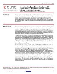
RProduct Obsolete/Under ObsolescenceChapter 2: Timing ModelsClock Event 1: Shift_InDuring a WRITE (Shift_In) operation, the single-bit content of the register at the address onthe ADDR inputs is changed, as data is shifted through the SRL. The data written to thisregister is reflected on the X/Y outputs synchronously, if the address is unchanged duringthe clock event. If the ADDR inputs are changed during a clock event, the value of the dataat the addressable output (D) is invalid.• At time T WSS before Clock Event 1, the Write Enable signal (SR) becomes valid-high,enabling the SRL for the WRITE operation that follows.• At time T SRLDS before Clock Event 1 the data becomes valid (0) at the DI input of the SRLand is reflected on the X/Y output after a delay of length T REG after Clock Event 1*.* Note: Since the address 0 is specified at Clock Event 1, the data on the DI input is reflected atthe D output, because it is written to Register 0.Clock Event 2: Shift_In• At time T SRLDS before Clock Event 2, the data becomes valid (1) at the DI input of theSRL and is reflected on the X/Y output after a delay of length T REG after Clock Event 2*.* Note: Since the address 0 is still specified at Clock Event 2, the data on the DI input is reflectedat the D output, because it is written to Register 0.Clock Event 3: Shift_In / Addressable (Asynchronous) READAll READ operations are asynchronous. If the address is changed (between clock events),the contents of the register at that address are reflected at the addressable output (X/Youtputs) after a delay of length T ILO (propagation delay through a LUT).• At time T SRLDS before Clock Event 3 the Data becomes valid (1) at the DI input of theSRL, and is reflected on the X/Y output T REG time after Clock Event 3.• Notice that the address is changed (from 0 to 2) some time after Clock Event 3. Thevalue stored in Register 2 at this time is a 0 (in this example, this was the first datashifted in), and it is reflected on the X/Y output after a delay of length T ILO .Clock Event 16: MSB (Most Significant Bit) Changes• At time T REGXB after Clock Event 16, the first bit shifted into the SRL becomes valid(logical 0 in this case) on the XB output of the slice via the MC15 output of the LUT(SRL).Block SelectRAM Timing ModelIntroductionThis section describes the timing parameters associated with the block SelectRAM(illustrated in Figure 2-7) in <strong>Virtex</strong>-<strong>II</strong> <strong>FPGA</strong> devices. This section is intended to be usedwith the section on switching characteristics in the <strong>Virtex</strong>-<strong>II</strong> Data Sheet (DS031) and theTiming Analyzer (TRCE) report from <strong>Xilinx</strong> software. For specific timing parametervalues, refer to the switching characteristics section in the <strong>Virtex</strong>-<strong>II</strong> Data Sheet.30 www.xilinx.com <strong>UG002</strong> (v2.2) 5 November 2007<strong>Virtex</strong>-<strong>II</strong> <strong>Platform</strong> <strong>FPGA</strong> <strong>User</strong> <strong>Guide</strong>
Block SelectRAM Timing ModelProduct Obsolete/Under ObsolescenceRDIDIPADDRWEENSSRCLKDODOPDS031_10_071602Figure 2-7:Block SelectRAM Block DiagramTiming ParametersTable 2-4:ParameterBlock SelectRAM Timing ParametersFunctionControlSignalDescriptionSetup and Hold Relative to Clock (CLK)T BxCK = Setup time (before clock edge)T BCKx = Hold time (after clock edge)T BACK /T BCKA Address inputs ADDRT BDCK /T BCKD Data inputs DIT BECK /T BCKE Enable ENThe following descriptions are for setup times only.Time before the clock that address signals mustbe stable at the ADDR inputs of the block RAM.Time before the clock that data must be stable atthe DI inputs of the block RAM.Time before the clock that the enable signal mustbe stable at the EN input of the block RAM.T BRCK /T BCKRSynchronousSet/ResetSSRTime before the clock that the synchronousset/reset signal must be stable at the SSR input ofthe block RAM.T BWCK /T BCKW Write Enable WETime before the clock that the write enable signalmust be stable at the WE input of the block RAM.Clock to OutT BCKOClock to OutputCLK toDOTime after the clock that the output data is stableat the DO outputs of the block RAM.ClockT BPWH Clock CLK Minimum pulse width, high.T BPWL Clock CLK Minimum pulse width, low.<strong>UG002</strong> (v2.2) 5 November 2007 www.xilinx.com 31<strong>Virtex</strong>-<strong>II</strong> <strong>Platform</strong> <strong>FPGA</strong> <strong>User</strong> <strong>Guide</strong>
RProduct Obsolete/Under ObsolescenceChapter 2: Timing ModelsTiming CharacteristicsThe timing diagram in Figure 2-8 describes a single-port block RAM in Write-First mode.The timing for Read-First and No-Change modes are similar (see chapter 2, block RAMsection.)CLKADDRDI1 2 3 45T BPWHT BPWLT BACK00T BDCKDDDD0F 7E 8F 20CCCC BBBB AAAA 0000DOT BCKOMEM (00)CCCC* MEM (7E) 0101**ENSSRT BECKT BWCKT BRCKWEDisabledRead Write Read ResetDisabled* Write Mode = "WRITE_FIRST"** SRVAL = 0101Figure 2-8:Block SelectRAM Timing Diagramug002_c3_002_100300At time 0, the block RAM is disabled; EN (enable) is low.Clock Event 1: READ OperationDuring a read operation, the contents of the memory at the address on the ADDR inputsare unchanged.• T BACK before Clock Event 1, address 00 becomes valid at the ADDR inputs of theblock RAM.• At time T BECK before Clock Event 1, Enable goes High at the EN input of the blockRAM, enabling the memory for the READ operation that follows.• At time T BCKO after Clock Event 1, the contents of the memory at address 00 becomestable at the DO pins of the block RAM.Clock Event 2: WRITE OperationDuring a write operation, the content of the memory at the location specified by theaddress on the ADDR inputs is replaced by the value on the DI pins and is immediatelyreflected on the output latches (in WRITE-FIRST mode); EN (enable) is high.• At time T BACK before Clock Event 2, address 0F becomes valid at the ADDR inputs ofthe block RAM.• At time T BDCK before Clock Event 2, data CCCC becomes valid at the DI inputs of theblock RAM.• At time T BWCK before Clock Event 2, Write Enable becomes valid at the WE followingthe block RAM.• At time T BCKO after Clock Event 2, data CCCC becomes valid at the DO outputs of theblock RAM.32 www.xilinx.com <strong>UG002</strong> (v2.2) 5 November 2007<strong>Virtex</strong>-<strong>II</strong> <strong>Platform</strong> <strong>FPGA</strong> <strong>User</strong> <strong>Guide</strong>
Block SelectRAM Timing ModelProduct Obsolete/Under ObsolescenceRClock Event 4: SSR (Synchronous Set/Reset) OperationDuring an SSR operation, initialization parameter value SRVAL is loaded into the outputlatches of the block SelectRAM. The SSR operation does NOT change the contents of thememory and is independent of the ADDR and DI inputs.• At time T BRCK before Clock Event 4, the synchronous set/reset signal becomes valid(High) at the SSR input of the block RAM.• At time T BCKO after Clock Event 4, the SRVAL 0101 becomes valid at the DO outputsof the block RAM.Clock Event 5: Disable OperationDe-asserting the enable signal EN disables any write, read or SSR operation. The disableoperation does NOT change the contents of the memory or the values of the output latches.• At time T BECK before Clock Event 5, the enable signal becomes valid (Low) at the ENinput of the block RAM.• After Clock Event 5, the data on the DO outputs of the block RAM is unchanged.Timing ModelFigure 2-9 illustrates the delay paths associated with the implementation of blockSelectRAM. This example takes the simplest paths on and off chip (these paths can varygreatly depending on the design). This timing model demonstrates how and where theblock SelectRAM timing parameters are used.<strong>FPGA</strong>Block SelectRAMDataAddressWrite EnableEnableSynchronousSet/Reset[T IOPI + NET] + T BDCK[T IOPI + NET] + T BACK[T IOPI + NET*] + T BWCK[T IOPI + NET] + T BECK[T IOPI + NET] + T BRCKDIADDRWEENSSRCLKDOT BCKO + [NET + T IOOP ]Data[T GI0O + NET]BUFGMUXClock[T IOPI + NET]ug002_c3_003_101300Figure 2-9:Block SelectRAM Timing ModelNET = Varying interconnect delaysT IOPI = Pad to I-output of IOB delayT IOOP = O-input of IOB to pad delayT GI0O = BUFGMUX delay<strong>UG002</strong> (v2.2) 5 November 2007 www.xilinx.com 33<strong>Virtex</strong>-<strong>II</strong> <strong>Platform</strong> <strong>FPGA</strong> <strong>User</strong> <strong>Guide</strong>
RProduct Obsolete/Under ObsolescenceChapter 2: Timing ModelsEmbedded Multiplier Timing ModelIntroductionThis section explains all timing parameters associated with the use of embedded18-bit x 18-bit multipliers in <strong>Virtex</strong>-<strong>II</strong> <strong>FPGA</strong>s (see Figure 2-10). The propagation delaysthrough the embedded multiplier differ based on the size of the multiplier functionimplemented. The longest delay through the multiplier is to the highest order bit output(P35). Therefore, if an 18-bit x 18-bit signed multiplier is implemented, the worst-casedelay for this function is the longest delay associated with the embedded multiplier block.If smaller (LSB) multipliers are used, shorter delays can be realized.This section is intended to be used in conjunction with the section on switchingcharacteristics in the <strong>Virtex</strong>-<strong>II</strong> Data Sheet (DS031) and the Timing Analyzer (TRCE) reportfrom <strong>Xilinx</strong> software. For specific timing parameter values, refer to the <strong>Virtex</strong>-<strong>II</strong> Data Sheet.A[17:0]Multiplier BlockMULT 18 x 18P[35:0]B[17:0]Figure 2-10:DS031_40_100400Embedded 18-bit x 18-bit Multiplier BlockTiming ParametersWorst-Case Propagation DelaysThe T MULT timing parameter is reported by the Timing Analyzer software. These valuescorrespond to the propagation delay through the multiplier to a specific output pin of themultiplier block. The shortest delay is to pin 0, the longest to pin 35. These parameters canbe found in the table entitled “Multiplier Switching Characteristics” in Module 3 of the<strong>Virtex</strong>-<strong>II</strong> <strong>Platform</strong> <strong>FPGA</strong> Data Sheet. The delay-to-pin ratio is essentially linear (seeFigure 2-11). This implies that smaller multiply functions are faster than larger ones. This istrue as long as the LSB inputs are used.Pin 35Pin 0Delay<strong>UG002</strong>_C3_023_092500Figure 2-11:Pin-to-Delay Ratio Curve34 www.xilinx.com <strong>UG002</strong> (v2.2) 5 November 2007<strong>Virtex</strong>-<strong>II</strong> <strong>Platform</strong> <strong>FPGA</strong> <strong>User</strong> <strong>Guide</strong>
Embedded Multiplier Timing ModelProduct Obsolete/Under ObsolescenceRTiming CharacteristicsFigure 2-12 illustrates the result (outputs) of a 4-bit x 4-bit unsigned multiply implementedin an embedded multiplier block.Time 0input[3..0]1111input[3..0]1111T MULT (P0)P0X1T MULT (P1)P1X0P2TMULT (P2)XTMULT (P3)0P3XTMULT (P4)0P4XTMULT (P5)0P5XTMULT (P6)1P6XTMULT (P7)1P7X1Figure 2-12:Embedded Multiplier Block Timing Diagram<strong>UG002</strong>_C3_024_101300At time 0 the two 4-bit numbers to be multiplied become valid at the A[0..3], B[0..3] inputsto the embedded multiplier. The result appears on the output pins P[0..7] in a staggeredfashion. First, P0 becomes valid at time T MULT (P0), followed by each subsequent outputpin, until P7 becomes valid at time T MULT (P7). In this case, the delay for this multiplyfunction should correspond to that of Pin 7. In other words, the result is not valid until alloutput pins become valid.<strong>UG002</strong> (v2.2) 5 November 2007 www.xilinx.com 35<strong>Virtex</strong>-<strong>II</strong> <strong>Platform</strong> <strong>FPGA</strong> <strong>User</strong> <strong>Guide</strong>
RIOB Timing ModelProduct Obsolete/Under ObsolescenceChapter 2: Timing ModelsThe following three sections describe all timing parameters associated with the <strong>Virtex</strong>-<strong>II</strong>IOB. These three sections are:• IOB Input Timing Model and Parameters• IOB Output Timing Model and Parameters• IOB 3-State Timing Model and ParametersThis section is intended to be used in conjunction with the section on switchingcharacteristics in the <strong>Virtex</strong>-<strong>II</strong> Data Sheet (DS031) and the Timing Analyzer (TRCE) reportfrom <strong>Xilinx</strong> software. For specific timing parameter values, refer to the <strong>Virtex</strong>-<strong>II</strong> Data Sheet.A Note on I/O Standard Adjustments:The "IOB Input and Output Switching Characteristics Standard Adjustments" tables in theswitching characteristics section of the <strong>Virtex</strong>-<strong>II</strong> Data Sheet are delay adders (+/-) to beadded to all timing parameter values associated with the IOB and the Global Clock (see"Pin-to-Pin Timing Model" on page 48), if an I/O standard other than LVTTL is used.All values specified in the <strong>Virtex</strong>-<strong>II</strong> Data Sheet for the parameters covered in this section arespecified for LVTTL. If another I/O standard is used, these delays change. However, thereare several exceptions. The following parameters associated with the pad going to highimpedance(3-State buffer OFF) should NOT be adjusted:• T IOTHZ• T IOTLPHZ• T GTS• T IOCKHZ• T IOSRHZ36 www.xilinx.com <strong>UG002</strong> (v2.2) 5 November 2007<strong>Virtex</strong>-<strong>II</strong> <strong>Platform</strong> <strong>FPGA</strong> <strong>User</strong> <strong>Guide</strong>
IOB Timing ModelProduct Obsolete/Under ObsolescenceIOB Input Timing Model and ParametersFigure 2-13 illustrates IOB inputs.RPADID1FFLATCHQ1IQ1ICLK1CESRREVICED2FFLATCHQ2IQ2CEICLK2SRREVSRREV<strong>UG002</strong>_C3_004_101300Figure 2-13:<strong>Virtex</strong>-<strong>II</strong> IOB Input DiagramTiming ParametersTable 2-5:ParameterIOB Input Timing ParametersFunctionControlSignalDescriptionPropagation DelaysT IOPIT IOPIDT IOPLIT IOPLIDPropagation delay from the pad to Ioutput of the IOB with no delay adder.Propagation delay from the pad to Ioutput of the IOB with the delay adder.Propagation delay from the pad to IQoutput of the IOB via transparent latchwith no delay adder.Propagation delay from the pad to IQoutput of the IOB via transparent latchwith the delay adder.<strong>UG002</strong> (v2.2) 5 November 2007 www.xilinx.com 37<strong>Virtex</strong>-<strong>II</strong> <strong>Platform</strong> <strong>FPGA</strong> <strong>User</strong> <strong>Guide</strong>
RProduct Obsolete/Under ObsolescenceChapter 2: Timing ModelsTable 2-5:IOB Input Timing Parameters (Continued)ParameterFunctionControlSignalDescriptionSetup and Hold With Respect to Clock at IOB Input RegisterT xxCK = Setup time (before clock edge)T xxCKxx = Hold time (after clock edge)T IOPICK /T IOICKPID input with NOdelayThe following descriptions are forsetup times only.Time before the clock that the input signalfrom the pad must be stable at the ID inputof the IOB Input Register, with no delay.T IOPICKD /T IOICKPDT IOICECK /T IOCKICET IOSRCKIClock to OutT IOCKIQSet/Reset DelaysT IOSRIQT GSRQID input with delayICE inputSR input (IFF,synchronous)Clock (CLK) to (IQ)outputSR Input to IQ(asynchronous)GSR to output IQTime before the clock that the input signalfrom the pad must be stable at the IDinput of the IOB Input Register, withdelay.Time before the clock that the ClockEnable signal must be stable at the ICEinput of the IOB Input Register.Time before the clock that the Set/Resetsignal must be stable at the SR input of theIOB Input Register.Time after the clock that the output data isstable at the IQ output of the IOB InputRegister.Time after the Set/Reset signal of the IOBis toggled that the output of the IOB inputregister (IQ) reflects the signal.Time after the Global Set/Reset is toggledthat the output of the IOB input register(IQ) reflects the set or reset.38 www.xilinx.com <strong>UG002</strong> (v2.2) 5 November 2007<strong>Virtex</strong>-<strong>II</strong> <strong>Platform</strong> <strong>FPGA</strong> <strong>User</strong> <strong>Guide</strong>
IOB Timing ModelProduct Obsolete/Under ObsolescenceRTiming CharacteristicsFigure 2-14 illustrates IOB input register timing.1 2 3 4 5CLKTIOPICKITIOICECKICESR(reset)IQTIOCKIQTIOSRCKITIOCKIQFigure 2-14:IOB Input Register Timing Diagram<strong>UG002</strong>_c3_005_112700Clock Event 1• At time T IOICECK before Clock Event 1, the input clock enable signal becomes valid-highat the ICE input of the input register, enabling the input register for incoming data.• At time T IOPICK before Clock Event 1, the input signal becomes valid-high at the Iinput of the input register and is reflected on the IQ output of the input register attime T IOCKIQ after Clock Event 1.Clock Event 4• At time T IOSRCKI before Clock Event 4 the SR signal (configured as synchronous resetin this case) becomes valid-high resetting the input register and reflected at the IQoutput of the IOB at time T IOCKIQ after Clock Event 4.<strong>UG002</strong> (v2.2) 5 November 2007 www.xilinx.com 39<strong>Virtex</strong>-<strong>II</strong> <strong>Platform</strong> <strong>FPGA</strong> <strong>User</strong> <strong>Guide</strong>
RProduct Obsolete/Under ObsolescenceChapter 2: Timing ModelsTiming Characteristics, DDRFigure 2-15 illustrates IOB DDR input register timing.1 2 3 4 5 6 7 8 9 10 11ICLK1ICLK2TIOPICK<strong>II</strong>CESR(reset)TIOCKIQIQ1TIOICECKTIOPICKTIOSRCKTIOCKIQIQ2TIOCKIQTIOCKIQ<strong>UG002</strong>_c3_006_112700Figure 2-15:IOB DDR Input Register Timing DiagramClock EventsClock Event 1• At time T IOICECK before Clock Event 1 the input clock enable signal becomes validhighat the ICE input of both of the DDR input registers, enabling them for incomingdata. Since the ICE and I signals are common to both DDR registers, care must betaken to toggle these signals between the rising edges of ICLK1 and ICLK2 as well asmeeting the register setup-time relative to both clocks.• At time T IOPICK before Clock Event 1 (rising edge of ICLK1) the input signal becomesvalid-high at the I input of both registers and is reflected on the IQ1 output of inputregister1 at time T IOCKIQ after Clock Event 1.Clock Event 2At time T IOPICK before Clock Event 2 (rising edge of ICLK2) the input signal becomesvalid-low at the I input of both registers and is reflected on the IQ2 output of input-register2 at time T IOCKIQ after Clock Event 2 (no change in this case).Clock Event 9At time T IOSRCKI before Clock Event 9 the SR signal (configured as synchronous reset inthis case) becomes valid-high resetting input-register 1 (IQ1) at time T IOCKIQ after ClockEvent 9, and input-register 2 (IQ2) at time T IOCKIQ after Clock Event 10.40 www.xilinx.com <strong>UG002</strong> (v2.2) 5 November 2007<strong>Virtex</strong>-<strong>II</strong> <strong>Platform</strong> <strong>FPGA</strong> <strong>User</strong> <strong>Guide</strong>
IOB Timing ModelProduct Obsolete/Under ObsolescenceIOB Output Timing Model and ParametersFigure 2-16 illustrates IOB outputs.RO1Sharedby allregistersOCEOTCLK1SRREVD1FFLATCHQ1CECK1SR REVAttribute INIT1INIT0SRHIGHSRLOWFF1DDR MUXFF2OQ3-StateControlPADFFLATCHD2Q2OTCLK2O2CECK2SR REVAttributeINIT1INIT0SRHIGHSRLOWReset TypeSYNCASYNC<strong>UG002</strong>_C3_007_101300Figure 2-16:<strong>Virtex</strong>-<strong>II</strong> IOB Output DiagramTiming ParametersTable 2-6:ParameterIOB Output Timing ParametersFunctionControlSignalDescriptionPropagation DelaysT IOOPT IOOLPPropagation delay from the O input of theIOB to the pad.Propagation delay from the O input of theIOB to the pad via transparent latch.Setup and Hold With Respect to Clock at IOB Output RegisterT xxCK = Setup time (before clock edge)T xxCKxx = Hold time (after clock edge)The following descriptions are for setup timesonly.T IOOCK /T IOCKOT IOOCECK /T IOCKOCET IOSRCKO /T IOCKOSRO inputOCE inputSR input (OFF)Time before the clock that data must bestable at the O input of the IOB OutputRegister.Time before the clock that the ClockEnable signal must be stable at the OCEinput of the IOB Output Register.Time before the clock that the Set/Resetsignal must be stable at the SR input of theIOB Output Register.<strong>UG002</strong> (v2.2) 5 November 2007 www.xilinx.com 41<strong>Virtex</strong>-<strong>II</strong> <strong>Platform</strong> <strong>FPGA</strong> <strong>User</strong> <strong>Guide</strong>
RProduct Obsolete/Under ObsolescenceChapter 2: Timing ModelsTable 2-6:ParameterIOB Output Timing Parameters (Continued)FunctionControlSignalDescriptionClock to OutT IOCKPSet/Reset DelaysT IOSRPT IOGSRQClock (CLK) to padSR Input to pad(asynchronous)GSR to padTime after the clock that the output data isstable at the pad.Time after the Set/Reset input of the IOBis toggled that the pad reflects the set orreset.Time after the Global Set/Reset is toggledthat the pad reflects the set or reset.Timing CharacteristicsFigure 2-17 illustrates IOB output register timing.1 2 3 4 5CLKTIOOCKOTIOOCECKOCESR(reset)PADTIOCKPTIOSRCKO<strong>UG002</strong>_C3_008_112700Figure 2-17:IOB Output Register Timing DiagramClock Event 1• At time T IOOCECK before Clock Event 1, the output clock enable signal becomes validhighat the OCE input of the output register, enabling the output register for incomingdata.• At time T IOOCK before Clock Event 1, the output signal becomes valid-high at the Oinput of the output register and is reflected on the pad at time T IOCKP after ClockEvent 1.Clock Event 4At time T IOSRCKO before Clock Event 4, the SR signal (configured as synchronous reset inthis case) becomes valid-high, resetting the output register and reflected on the pad at timeT IOCKP after Clock Event 4.42 www.xilinx.com <strong>UG002</strong> (v2.2) 5 November 2007<strong>Virtex</strong>-<strong>II</strong> <strong>Platform</strong> <strong>FPGA</strong> <strong>User</strong> <strong>Guide</strong>
IOB Timing ModelProduct Obsolete/Under ObsolescenceRTiming Characteristics, DDRFigure 2-18 illustrates IOB DDR output register timing.1 2 3 4 5 6 7 8 9 10 11OTCLK1OTCLK2TIOOCKO1O2TIOOCKTIOOCECKOCESRTIOSRCKOPADTIOCKPTIOCKP<strong>UG002</strong>_c3_009_112700Figure 2-18:IOB DDR Output Register Timing DiagramClock Event 1• At time T IOOCECK before Clock Event 1, the output clock enable signal becomes validhighat the OCE input of both of the DDR output registers, enabling them forincoming data. Since the OCE signal is common to both DDR registers, care must betaken to toggle this signal between the rising edges of OTCLK1 and OTCLK2 as wellas meeting the register setup-time relative to both clocks.• At time T IOOCK before Clock Event 1 (rising edge of OTCLK1), the output signal O1becomes valid-high at the O1 input of output register 1 and is reflected on the pad attime T IOCKP after Clock Event 1.Clock Event 2*At time T IOOCK before Clock Event 2 (rising edge of OTCLK2), the output signal O2becomes valid-high at the O2 input of output register 2 and is reflected on the pad at timeT IOCKP after Clock Event 2 (no change on the pad in this case).Clock Event 9At time T IOSRCKO before Clock Event 9, the SR signal (configured as synchronous reset inthis case) becomes valid-high, resetting output-register 1 (reflected on the pad at timeT IOCKP after Clock Event 9) (no change in this case) and output-register 2 (reflected on thepad at time T IOCKP after Clock Event 10) (no change in this case).<strong>UG002</strong> (v2.2) 5 November 2007 www.xilinx.com 43<strong>Virtex</strong>-<strong>II</strong> <strong>Platform</strong> <strong>FPGA</strong> <strong>User</strong> <strong>Guide</strong>
RProduct Obsolete/Under ObsolescenceIOB 3-State Timing Model and ParametersFigure 2-19 illustrates IOB 3-state timingT1Chapter 2: Timing ModelsSharedby allregistersTCEOTCLK1SRREVD1CEFFLATCHQ1CK1SR REVAttributeINIT1INIT0SRHIGHSRLOWFF1DDR MUXFF2TQFFLATCHPADD2Q2OTCLK2CECK2SR REVAttribute INIT1INIT0SRHIGHSRLOWReset TypeT2SYNCASYNC<strong>UG002</strong>_C3_010_120600Figure 2-19:<strong>Virtex</strong>-<strong>II</strong> IOB 3-State DiagramTiming ParametersTable 2-7: IOB 3-State Timing ParametersParameterFunctionPropagation DelaysT IOTHZT IOTONT IOTLPHZT IOTLPONT GTSControlSignalDescriptionTime after T input of the IOB istoggled that the pad goes tohigh-impedance.Time after the T input of theIOB is toggled that the padgoes from high-impedance tovalid data.Time after the T input of theIOB via transparent latch istoggled that the pad goes tohigh-impedance.Time after the T input of the IOBvia transparent latch is toggledthat the pad goes from highimpedanceto valid data.Time after the Global 3-statesignal is asserted that the padgoes to high-impedance.44 www.xilinx.com <strong>UG002</strong> (v2.2) 5 November 2007<strong>Virtex</strong>-<strong>II</strong> <strong>Platform</strong> <strong>FPGA</strong> <strong>User</strong> <strong>Guide</strong>
IOB Timing ModelProduct Obsolete/Under ObsolescenceRTable 2-7:ParameterSetup and Hold With Respect to Clock at IOB 3-State RegisterT xxCK = Setup time (before clock edge)T xxCKxx = Hold time (after clock edge)T IOTCK /T IOCKTIOB 3-State Timing Parameters (Continued)FunctionT inputControlSignalDescriptionThe followingdescriptions are for setuptimes only.Time before the clock that thesignal must be stable at the Tinput of the IOB 3-stateRegister.T IOTCECK /T IOCKTCETCE inputTime before the clock that theclock enable signal must bestable at the TCE input of theIOB 3-state Register.T IOSRCKT /T IOCKTSR SR input (TFF)Time before the clock that theset/reset signal.Clock to OutT IOCKHZT IOCKONSet/Reset DelaysT IOSRHZT IOSRONClock (CLK) to pad High-ZClock (CLK) to valid data onpadSR Input to pad High-Z(asynchronous)SR Input to valid data on pad(asynchronous)Time after clock that the padgoes to high-impedance.Time after clock that the padgoes from high-impedance tovalid data.Time after the SR signal istoggled that the pad goes tohigh-impedance.Time after the SR signal istoggled that the pad goesfrom high-impedance to validdata.<strong>UG002</strong> (v2.2) 5 November 2007 www.xilinx.com 45<strong>Virtex</strong>-<strong>II</strong> <strong>Platform</strong> <strong>FPGA</strong> <strong>User</strong> <strong>Guide</strong>
RProduct Obsolete/Under ObsolescenceChapter 2: Timing ModelsTiming CharacteristicsFigure 2-20 illustrates IOB 3-state register timing.1 2 3 4 5CLKTIOTCKTTIOTCECKTCESRPADTIOCKHZTIOSRCKTTIOCKONDATA ZDATA ZDATA<strong>UG002</strong>_c3_011_101300Figure 2-20:IOB 3-State Register Timing DiagramClock Event 1• At time T IOTCECK before Clock Event 1, the 3-state clock enable signal becomes validhighat the TCE input of the 3-state register, enabling the 3-state register for incomingdata.• At time T IOTCK before Clock Event 1 the 3-state signal becomes valid-high at the Tinput of the 3-state register, returning the pad to high-impedance at time T IOCKHZafter Clock Event 1.Clock Event 2At time T IOSRCKT before Clock Event 2, the SR signal (configured as synchronous reset inthis case) becomes valid-high, resetting the 3-state register and returning the pad to validdata at time T IOSRON after Clock Event 2.46 www.xilinx.com <strong>UG002</strong> (v2.2) 5 November 2007<strong>Virtex</strong>-<strong>II</strong> <strong>Platform</strong> <strong>FPGA</strong> <strong>User</strong> <strong>Guide</strong>
IOB Timing ModelProduct Obsolete/Under ObsolescenceRTiming Characteristics, DDRFigure 2-21 illustrates IOB DDR 3-state register timing.1 2 3 4 5 6 7 8 9 10 11OTCLK1OTCLK2T1TIOTCKT2TIOTCKTIOTCECKTCESRTIOSRCKTTIOCKHZTIOCKONTIOSRONPAD DATA Z DATA Z DATA Z<strong>UG002</strong>_c3_012_101300Figure 2-21:IOB DDR 3-State Register Timing DiagramClock Event 1At time T IOTCECK before Clock Event 1, the 3-state clock enable signal becomes valid-highat the TCE input of both of the DDR 3-state registers, enabling them for incoming data.Since the TCE signal is common to both DDR registers, care must be taken to toggle thissignal between the rising edges of OTCLK1 and OTCLK2 as well as meeting the registersetup-time relative to both clocks.Clock Event 2At time T IOTCK before Clock Event 2 (rising edge of OTCLK2), the 3-state signal T2becomes valid-high at the T2 input of 3-state register 2, switching the pad to highimpedanceat time T IOCKHZ after Clock Event 2.Clock Event 3At time T IOTCK before Clock Event 3 (rising edge of OTCLK1), the 3-state signal T1becomes valid-high at the T1 input of 3-state register 1, keeping the pad at high-impedancefor another half clock cycle (half the period of OTCLK1 or 2).Clock Event 4At time T IOTCK before Clock Event 4 (rising edge of OTCLK2), the 3-state signal T2becomes valid-low at the T2 input of 3-state register 2, switching the pad to valid data attime T IOCKON after Clock Event 4. This is repeated for 3-state signal T1 at the followingclock event (5) maintaining valid data on the pad until Clock Event 8.Clock Event 8At time T IOTCK before Clock Event 8 (rising edge of OTCLK2), the 3-state signal T2becomes valid-high at the T2 input of 3-state register 2, switching the pad to highimpedanceat time T IOCKHZ after Clock Event 8.<strong>UG002</strong> (v2.2) 5 November 2007 www.xilinx.com 47<strong>Virtex</strong>-<strong>II</strong> <strong>Platform</strong> <strong>FPGA</strong> <strong>User</strong> <strong>Guide</strong>
RProduct Obsolete/Under ObsolescenceChapter 2: Timing ModelsClock Event 9At time T IOSRCKT before Clock Event 9 (rising edge of OTCLK1), the SR signal (configuredas synchronous reset in this case) becomes valid-high at the SR input of 3-state Register 1,returning the pad to valid data at time T IOSRON after Clock Event 9.Pin-to-Pin Timing ModelIntroductionThis section explains the delays and timing parameters associated with the use of theGlobal Clock network and the DCM. These delays are true pin-to-pin delays relative to theGlobal Clock pin and an output or input pin with or without the DCM.This section consists of two parts:• Global Clock Input to Output• Global Clock Setup and HoldThe former describes the delay from the Global Clock pin (with and without the DCM) toan output pin via an Output flip-flop. The latter describes the set-up time for an Input flipflopfrom an input pin relative to the Global Clock pin (with and without the DCM).The values reported in the switching characteristics section of the <strong>Virtex</strong>-<strong>II</strong> Data Sheet(DS031) are for LVTTL I/O standards. For different I/O standards, adjust these valueswith those shown in the "IOB Switching Characteristics Standard Adjustments" tables.This section is intended to be used in conjunction with the section on switchingcharacteristics in the <strong>Virtex</strong>-<strong>II</strong> Data Sheet and the Timing Analyzer (TRCE) report from<strong>Xilinx</strong> software. For specific timing parameter values, refer to the <strong>Virtex</strong>-<strong>II</strong> Data Sheet.48 www.xilinx.com <strong>UG002</strong> (v2.2) 5 November 2007<strong>Virtex</strong>-<strong>II</strong> <strong>Platform</strong> <strong>FPGA</strong> <strong>User</strong> <strong>Guide</strong>
Pin-to-Pin Timing ModelProduct Obsolete/Under ObsolescenceRGlobal Clock Input to OutputFigure 2-22 illustrates the paths associated with the timing parameters defined in thissection. Note that they differ only in their use of the DCM.Global Clock PinBUFGMUXDataIOB OutputRegisterDQOutputPinOutputPinIOB OutputRegisterQDDataDCMBUFGMUXGlobal Clock Pin<strong>UG002</strong>_C3_013_101300Figure 2-22:Global Clock Input to Output ModelTiming ParametersTable 2-8:Global Clock Input to Output Timing ParametersParameterT ICKOFDLLT ICKOFDescriptionTime after the Global Clock (pin), using the DCM, that the output datafrom an IOB Output flip-flop is stable at the output pin.Time after the Global Clock (pin), without the DCM, that the output datafrom an IOB Output flip-flop is stable at the output pin.<strong>UG002</strong> (v2.2) 5 November 2007 www.xilinx.com 49<strong>Virtex</strong>-<strong>II</strong> <strong>Platform</strong> <strong>FPGA</strong> <strong>User</strong> <strong>Guide</strong>
RProduct Obsolete/Under ObsolescenceChapter 2: Timing ModelsTiming CharacteristicsThe waveforms depicted in Figure 2-23 demonstrate the relation of the Global Clock pin,the output data, and the use of the timing parameters.Global Clock Pin(No DCM)D-input of IOBOutput RegisterOutput PinTICKOFGlobal Clock Pin(With DCM)D-input of IOBOutput RegisterOutput PinTICKOFDLL<strong>UG002</strong>_C3_015_101300Figure 2-23:Global Clock Input to Output Timing Diagram50 www.xilinx.com <strong>UG002</strong> (v2.2) 5 November 2007<strong>Virtex</strong>-<strong>II</strong> <strong>Platform</strong> <strong>FPGA</strong> <strong>User</strong> <strong>Guide</strong>
Pin-to-Pin Timing ModelProduct Obsolete/Under ObsolescenceRGlobal Clock Setup and HoldFigure 2-24 illustrates the paths associated with the timing parameters defined in thissection. Note, they differ only in their use of the DCM.Global Clock PinIOBBUFGMUXQDInputPinIOBInputPinDQDCMBUFGMUXGlobal Clock Pin<strong>UG002</strong>_C3_014_101300Figure 2-24:Global Clock Setup and Hold ModelTiming ParametersSetup and Hold for Input Registers Relative to the Global Clock (pin):• T PSDLL / T PHDLL - Time before the Global Clock (pin), with DCM, that the inputsignal must be stable at the D-input of the IOB input register.• T PSFD / T PHFD - Time before the Global Clock (pin), without DCM, that the inputsignal must be stable at the D-input of the IOB input register.Note: T PSFD = Setup time (before clock edge) and T PHFD = Hold time (after clock edge). Theprevious descriptions are for setup times only.<strong>UG002</strong> (v2.2) 5 November 2007 www.xilinx.com 51<strong>Virtex</strong>-<strong>II</strong> <strong>Platform</strong> <strong>FPGA</strong> <strong>User</strong> <strong>Guide</strong>
RProduct Obsolete/Under ObsolescenceChapter 2: Timing ModelsTiming CharacteristicsThe waveforms depicted in Figure 2-25 demonstrate the relation of the Global Clock pin,the input data, and the use of the timing parameters.Global Clock Pin(No DCM)Input PinTPSFDTPHFDGlobal Clock Pin(With DCM)Input PinTPSDLLTPHDLL<strong>UG002</strong>_C3_016_101300Figure 2-25:Global Clock Setup and Hold Timing Diagram52 www.xilinx.com <strong>UG002</strong> (v2.2) 5 November 2007<strong>Virtex</strong>-<strong>II</strong> <strong>Platform</strong> <strong>FPGA</strong> <strong>User</strong> <strong>Guide</strong>
Digital Clock Manager Timing ModelProduct Obsolete/Under ObsolescenceDigital Clock Manager Timing ModelThis section describes the timing parameters associated with the Digital Clock Manager(DCM), which are reported in the <strong>Virtex</strong>-<strong>II</strong> Data Sheet (DS031). Note that these parametersare not used by the Timing Analyzer software in the production of timing reports; they areall measured values and are fully characterized in silicon. For specific timing parametervalues, refer to the <strong>Virtex</strong>-<strong>II</strong> Data Sheet. This section discusses the following:• Operating Frequency Ranges: The minimum and maximum frequencies supportedby the DCM for all clock inputs and outputs.• Input Clock Tolerances: Input clock period (pulse widths), jitter, and driftrequirements for proper function of the DCM for all clock inputs.• Output Clock Precision: Output clock period jitter, phase offsets, and duty cycle forall clock outputs of the DCM (worst case).• Miscellaneous Timing Parameters: DCM lock times, Tap delay and shifting range.For a detailed description of input clock tolerance, jitter, and phase offset see thewaveforms at the end of this section.Operating Frequency RangesFigure 2-26 illustrates the DCM functional block and corresponding timing parameters forall clock inputs and outputs.RDCMCLKIN(CLKIN_FREQ_(DLL & FX)_(LF & HF))CLKFBPSINCDECPSENPSCLK_FREQ_(LF & HF)DSSENRSTCLK0 - CLKOUT_FREQ_1X_(LF & HF)CLK90 - CLKOUT_FREQ_1X_LFCLK180 - CLKOUT_FREQ_1X_(LF & HF)CLK270 - CLKOUT_FREQ_1X_LFCLK2X - CLKOUT_FREQ_2X_LFCLK2X180 - CLKOUT_FREQ_2X_LFCLKDV - CLKOUT_FREQ_DV_(LF & HF)CLKFX - CLKOUT_FREQ_FX_(LF & HF)CLKFX180 - CLKOUT_FREQ_FX_(LF & HF)PSDONELOCKEDSTATUSug002_c1_004_112800Figure 2-26:DCM Functional Block: Operating Frequency RangesTiming ParametersTable 2-9: Operating Frequency Range ParametersParameterDescriptionLow Frequency ModeCLKOUT_FREQ_1X_LFCLKOUT_FREQ_2X_LFThe minimum and maximum frequency for the CLK0, CLK90,CLK180, CLK270 outputs of the DCM in low-frequency mode.The minimum and maximum frequency for the CLK2X andCLK2X180 outputs of the DCM in low-frequency mode.<strong>UG002</strong> (v2.2) 5 November 2007 www.xilinx.com 53<strong>Virtex</strong>-<strong>II</strong> <strong>Platform</strong> <strong>FPGA</strong> <strong>User</strong> <strong>Guide</strong>
RProduct Obsolete/Under ObsolescenceChapter 2: Timing ModelsTable 2-9:Operating Frequency Range Parameters (Continued)ParameterCLKOUT_FREQ_DV_LFCLKOUT_FREQ_FX_LFCLKIN_FREQ_DLL_LF 1CLKIN_FREQ_FX_LF 2PSCLK_FREQ_LFDescriptionThe minimum and maximum frequency for the CLKDV output ofthe DCM in low-frequency mode.The minimum and maximum frequency for the CLKFX andCLKFX180 outputs of the DCM in low-frequency mode.The minimum and maximum frequency for the CLKIN input to theDCM in low-frequency mode when using the delay-locked loop(DLL) outputs.The minimum and maximum frequency for the CLKIN input to theDCM in low-frequency mode when using the FX outputs.The minimum and maximum frequency for the PSCLK input to theDCM in low-frequency mode.High Frequency ModeCLKOUT_FREQ_1X_HFCLKOUT_FREQ_DV_HFCLKOUT_FREQ_FX_HFCLKIN_FREQ_DLL_HFCLKIN_FREQ_FX_HFPSCLK_FREQ_HFThe minimum and maximum frequency for the CLK0, CLK180outputs of the DCM in high-frequency mode.The minimum and maximum frequency for the CLKDV output ofthe DCM in high-frequency mode.The minimum and maximum frequency for the CLKFX andCLKFX180 outputs of the DCM in high-frequency mode.The minimum and maximum frequency for the CLKIN input to theDCM in high-frequency mode when using the DLL outputs.The minimum and maximum frequency for the CLKIN input to theDCM in high-frequency mode when using the FX outputs.The minimum and maximum frequency for the PSCLK input to theDCM in high-frequency mode.Notes:1. Delay-locked loop (DLL) outputs include: CLK0, CLK90, CLK180, CLK270, CLK2X, CLK2X180,and CLKDV.2. FX outputs include: CLKFX and CLKFX180Input Clock TolerancesTiming ParametersTable 2-10:Input Clock Tolerance ParametersParameterPSCLK_PULSE 1CLKIN_PULSECLKFB_DELAY_VAR_EXTDescriptionThe minimum pulse width (HIGH and LOW) that thePSCLK input to the DCM can have over a range offrequencies.The minimum pulse width (HIGH and LOW) that theCLKIN input to the DCM can have over a range offrequencies. Also applies to PSCLK.The maximum allowed variation in delay (acrossenvironmental changes) of the feedback clock path whenrouted externally for board-level de-skew.Low Frequency Mode54 www.xilinx.com <strong>UG002</strong> (v2.2) 5 November 2007<strong>Virtex</strong>-<strong>II</strong> <strong>Platform</strong> <strong>FPGA</strong> <strong>User</strong> <strong>Guide</strong>
Digital Clock Manager Timing ModelProduct Obsolete/Under ObsolescenceRTable 2-10:Input Clock Tolerance Parameters (Continued)ParameterCLKIN_CYC_JITT_DLL_LFCLKIN_CYC_JITT_FX_LFCLKIN_PER_JITT_DLL_LFCLKIN_PER_JITT_FX_LFDescriptionThe maximum cycle-to-cycle jitter the CLKIN input to theDCM can have when using the DLL outputs in lowfrequencymode.The maximum cycle-to-cycle jitter the CLKIN input to theDCM can have when using the FX outputs in low-frequencymode.The maximum period jitter the CLKIN input to the DCM canhave when using the DLL outputs in low-frequency mode.The maximum period jitter the CLKIN input to the DCM canhave when using the FX outputs in low-frequency mode.High Frequency ModeCLKIN_CYC_JITT_DLL_HFCLKIN_CYC_JITT_FX_HFCLKIN_PER_JITT_DLL_HFCLKIN_PER_JITT_FX_HFThe maximum cycle-to-cycle jitter the CLKIN input to theDCM can have when using the DLL outputs in highfrequencymode.The maximum cycle-to-cycle jitter the CLKIN input to theDCM can have when using the FX outputs in high-frequencymode.The maximum period jitter the CLKIN input to the DCM canhave when using the DLL outputs in high-frequency mode.The maximum period jitter the CLKIN input to the DCM canhave when using the FX outputs in high-frequency mode.Notes:1. The frequencies applicable to CLKIN_PULSE range from 1 to >400 MHz. These frequenciesalso apply to PSCLK_PULSE. Since PSCLK can be less than 1 MHz, the pulse width under thiscondition is specified for PSCLK only.Output Clock PrecisionTiming ParametersTable 2-11:Output Clock Precision ParametersParameterCLKOUT_PER_JITT_0CLKOUT_PER_JITT_90CLKOUT_PER_JITT_180CLKOUT_PER_JITT_270CLKOUT_PER_JITT_2XCLKOUT_PER_JITT_DV1CLKOUT_PER_JITT_DV2DescriptionThe maximum period jitter of the CLK0 output clock fromthe DCM (worst case).The maximum period jitter of the CLK90 output clock fromthe DCM (worst case).The maximum period jitter of the CLK180 output clockfrom the DCM (worst case).The maximum period jitter of the CLK270 output clockfrom the DCM (worst case).The maximum period jitter of the CLK2X and CLK2X180output clocks from the DCM (worst case).The maximum period jitter of the CLKDV (integer division)output clock from the DCM (worst case).The maximum period jitter of the CLKDV (non-integerdivision) output clock from the DCM (worst case).<strong>UG002</strong> (v2.2) 5 November 2007 www.xilinx.com 55<strong>Virtex</strong>-<strong>II</strong> <strong>Platform</strong> <strong>FPGA</strong> <strong>User</strong> <strong>Guide</strong>
RProduct Obsolete/Under ObsolescenceChapter 2: Timing ModelsTable 2-11:Output Clock Precision Parameters (Continued)ParameterCLKOUT_PER_JITT_FXCLKIN_CLKFB_PHASECLKOUT_PHASECLKOUT_DUTY_CYCLE_DLLCLKOUT_DUTY_CYCLE_FXDescriptionThe maximum period jitter of the FX output clocks from theDCM (worst case).Maximum phase offset between the CLKIN and CLKFBinputs to the DCM.Maximum phase offset between any DCM clock outputs.The duty-cycle precision for all DLL outputs.The duty-cycle precision for the FX outputs.Miscellaneous DCM Timing ParametersTable 2-12:Miscellaneous DCM Timing ParametersParameterDescriptionLOCK_DLLLOCK_FXLOCK_DLL_FINE_SHIFTFINE_SHIFT_RANGEDCM_TAPTime required for DCM to lock over a range of clockfrequencies when using the DLL outputs.Time required for DCM to lock when using the FX outputs.Additional lock time when performing fine phase shifting.Absolute range for fine phase shifting.Resolution of delay line.The waveforms in Figure 2-27 demonstrate the relationship between clock tolerance, jitter,and phase.Period Tolerance: the allowed input clock period change in nanoseconds.T CLKINOutput Jitter: the difference between an idealreference clock edge and the actual design.T CLKIN+ _ InputClockJitterPhase Offset and Maximum Phase DifferenceIdeal PeriodActual Period+ JitterFigure 2-27:+/- Jitter+ Maximum Phase Difference+ Phase OffsetDCM Jitter, Phase, and Tolerance Timing Waveformsds022_24_112800Output jitter is period jitter measured on the DLL output clocks, excluding input clockjitter.Phase offset between CLKIN and CLKFB is the worst-case fixed time difference betweenrising edges of CLKIN and CLKFB, excluding output jitter and input clock jitter.56 www.xilinx.com <strong>UG002</strong> (v2.2) 5 November 2007<strong>Virtex</strong>-<strong>II</strong> <strong>Platform</strong> <strong>FPGA</strong> <strong>User</strong> <strong>Guide</strong>
Digital Clock Manager Timing ModelProduct Obsolete/Under ObsolescenceRPhase offset between clock outputs on the DLL is the worst-case fixed time differencebetween rising edges of any two DLL outputs, excluding output jitter and input clock jitter.Maximum phase difference between CLKIN an CLKFB is the sum of output jitter andphase offset between CLKIN and CLKFB, or the greatest difference between CLKIN andCLKFB rising edges due to DLL alone (excluding input clock jitter).Maximum phase difference between clock outputs on the DLL is the sum of output jitterand phase offset between any DLL clock outputs, or the greatest difference between anytwo DLL output rising edges due to DLL alone (excluding input clock jitter).<strong>UG002</strong> (v2.2) 5 November 2007 www.xilinx.com 57<strong>Virtex</strong>-<strong>II</strong> <strong>Platform</strong> <strong>FPGA</strong> <strong>User</strong> <strong>Guide</strong>
RProduct Obsolete/Under ObsolescenceChapter 2: Timing Models58 www.xilinx.com <strong>UG002</strong> (v2.2) 5 November 2007<strong>Virtex</strong>-<strong>II</strong> <strong>Platform</strong> <strong>FPGA</strong> <strong>User</strong> <strong>Guide</strong>
Product Obsolete/Under ObsolescenceRChapter 3Design ConsiderationsSummaryThis chapter covers the following topics:• Using Global Clock Networks• Using Digital Clock Managers (DCMs)• Using Block SelectRAM Memory• Using Distributed SelectRAM Memory• Using Look-Up Tables as Shift Registers (SRLs)• Designing Large Multiplexers• Implementing Sum of Products (SOP) Logic• Using Embedded Multipliers• Using Single-Ended SelectI/O-Ultra Resources• Using Digitally Controlled Impedance (DCI)• Using Double-Data-Rate (DDR) I/O• Using LVDS I/O• Using LVPECL I/O• Using Bitstream Encryption• Using the CORE Generator SystemIntroductionThis chapter describes how to take advantage of the many special features of the <strong>Virtex</strong>-<strong>II</strong>architecture to achieve maximum density and performance. In many cases, the functionsdescribed can be automatically generated using the <strong>Xilinx</strong> CORE Generator tool. This isnoted throughout the chapter, specifically in the following sections:• Using Block SelectRAM Memory• Using Distributed SelectRAM Memory• Using Look-Up Tables as Shift Registers (SRLs)• Designing Large Multiplexers• Using Embedded Multipliers<strong>UG002</strong> (v2.2) 5 November 2007 www.xilinx.com 59<strong>Virtex</strong>-<strong>II</strong> <strong>Platform</strong> <strong>FPGA</strong> <strong>User</strong> <strong>Guide</strong>
RProduct Obsolete/Under ObsolescenceChapter 3: Design ConsiderationsUsing Global Clock NetworksIntroduction<strong>Virtex</strong>-<strong>II</strong> devices support very high frequency designs and thus require low-skewadvanced clock distribution. With device density up to 10 million system gates, numerousglobal clocks are necessary in most designs. Therefore, to provide a uniform and portablesolution (soft-IP), all <strong>Virtex</strong>-<strong>II</strong> devices from XC2V40 to XC2V8000 have 16 global clock buffersand support 16 global clock domains. Up to eight of these clocks can be used in anyquadrant of the device by the synchronous logic elements (that is, registers, 18Kb blockRAM, pipeline multipliers) and the IOBs. The software tools place and route these globalclocks automatically.If the design uses between 8 and 16 clocks, it must be partitioned into quadrants, with upto 8 clocks per quadrant. If more than 16 clocks are required, the backbone (24 horizontaland vertical long lines routing resources) can be used as additional clock network.In addition to clock distribution, the 16 clock buffers are also “glitch-free” synchronous 2:1multiplexers. These multiplexers are capable of switching between two asynchronous (orsynchronous) clocks at any time. No particular phase relations between the two clocks areneeded. The clock multiplexers can also be configured as a global clock buffer with a clockenable. The clock can be stopped High or Low at the clock buffer output.Clock Distribution ResourcesThe various resources available to manage and distribute the clocks include:• 16 clock pads that can be used as regular user I/Os if not used as clock inputs. The 16clock pads can be configured for any I/O standard, including differential standards(for example, LVDS, LVPECL, and so forth).• 16 “IBUFG” elements that represent the clock inputs in a VHDL or Verilog design.• 8 “IBUFGDS” elements (that is, attributes LVPECL_33, LVDS_25, LVDS_33, LDT_25,or ULVDS_25) that represent the differential clock input pairs in a VHDL or Verilogdesign. Each IBUFGDS replaces two IBUFG elements.• 4 to 12 Digital Clock Managers (DCMs), depending on the device size, to de-skew andgenerate the clocks. For more information on DCMs, see "Using Digital ClockManagers (DCMs)" on page 80.• 16 “BUFGMUX” elements that can consist of up to 16 global clock buffers (BUFG),global clock buffers with a clock enable (BUFGCE), or global clock multiplexers(BUFGMUX).Figure 3-1 illustrates the placement of these clock resources in <strong>Virtex</strong>-<strong>II</strong> devices (theXC2V250 through the XC2V2000) that have eight DCMs.60 www.xilinx.com <strong>UG002</strong> (v2.2) 5 November 2007<strong>Virtex</strong>-<strong>II</strong> <strong>Platform</strong> <strong>FPGA</strong> <strong>User</strong> <strong>Guide</strong>
Using Global Clock NetworksProduct Obsolete/Under ObsolescenceR8 GCLK Pads<strong>User</strong> I/Os<strong>User</strong> I/OsIBUFGIBUFGDCMDCM8 BUFGMUXDCMDCMBRAMMultiplierCLBBRAMMultiplierBRAMMultiplierCLBBRAMMultiplier16 ClockDomainsBRAMMultiplierCLBBRAMMultiplierBRAMMultiplierCLBBRAMMultiplierDCMDCM8 BUFGMUXDCMDCMIBUFGIBUFG<strong>User</strong> I/Os<strong>User</strong> I/Os8 GCLK Pads<strong>UG002</strong>_C2_092_120100Figure 3-1:Clock Resources in <strong>Virtex</strong>-<strong>II</strong> DevicesThe simple scheme to distribute an external clock in the device is to implement a clock padwith an IBUFG input buffer connected to a BUFG global buffer, as shown in Figure 3-2 andFigure 3-3. The primary (GCLKP) and secondary (GCLKS) clock pads have no relationshipwith the P-side and N-side of differential clock inputs. In banks 0 and 1, the GCLKP correspondsto the N-side, and the GCLKS corresponds to the P-side of a differential clockinput. In banks 4 and 5, this correspondence is reversed..IBUFGBUFGGCLKPADI O I OClock DistributionClock InputIBUFGDSBUFGGCLKSGCLKPPN<strong>II</strong>BO I OClock DistributionDifferential ClockInputFigure 3-2:(Bank 0 and 1 Scheme)<strong>UG002</strong>_C2_105_080601Simple Clock Distribution (Bank 0 and 1 Scheme)<strong>UG002</strong> (v2.2) 5 November 2007 www.xilinx.com 61<strong>Virtex</strong>-<strong>II</strong> <strong>Platform</strong> <strong>FPGA</strong> <strong>User</strong> <strong>Guide</strong>
RProduct Obsolete/Under ObsolescenceChapter 3: Design ConsiderationsIBUFGBUFGGCLKPADI O I OClock DistributionClock InputIBUFGDSBUFGGCLKPGCLKSPN<strong>II</strong>BO I OClock DistributionDifferential ClockInput(Bank 4 and 5 Scheme)<strong>UG002</strong>_C2_084_080601Figure 3-3:Simple Clock Distribution (Bank 4 and 5 Scheme)Major synthesis tools automatically infer the IBUFG and BUFG when the correspondinginput signal is used as a clock in the VHDL or Verilog code.A high frequency or adapted (frequency, phase, and so forth) clock distribution with lowskew is implemented by using a DCM between the output of the IBUFG and the input ofthe BUFG, as shown in Figure 3-4. "Using Digital Clock Managers (DCMs)" on page 80provides details about DCMs and their use.IBUFGDCMBUFGGCLKPadI O CLKIN CLK0 I OClock DistributionCLKFB<strong>UG002</strong>_C2_085_050503Figure 3-4:Clock Distribution with DCMClock distribution from internal sources is also possible with a BUFG only or with a DCM,as shown in Figure 3-5.BUFGLogicI O Clock DistributionDCMBUFGLogicCLKINCLKOI O Clock DistributionCLKFB<strong>UG002</strong>_C2_086_050503Figure 3-5:Internal Logic Driving Clock Distribution62 www.xilinx.com <strong>UG002</strong> (v2.2) 5 November 2007<strong>Virtex</strong>-<strong>II</strong> <strong>Platform</strong> <strong>FPGA</strong> <strong>User</strong> <strong>Guide</strong>
Using Global Clock NetworksProduct Obsolete/Under ObsolescenceRGlobal Clock InputsThe clock buffer inputs are fed either by one of the 16 clock pads (refer to the <strong>Virtex</strong>-<strong>II</strong> DataSheet (DS031)), by the outputs of the DCM, or by local interconnect. Each clock buffer canbe a synchronous “glitch-free” 2:1 multiplexer with two clock inputs and one select input.Internal logic (or alternatively a regular IOB) can feed the clock inputs. Any internal orexternal signal can drive the select input or clock enable input.The possible inputs driving a global clock buffer or multiplexer are summarized inTable 3-1.Table 3-1:Inputs Driving Global Clock Buffers or DCMsDestinationSourceBUFG(I) orBUFGCE(I)BUFGCE(CE)BUFGMUX(I0 or I1)BUFGMUX(S)DCM(CLKIN)External Clock via IBUFG(O)Dedicated insame quadrant 1NADedicated insame quadrant 1 NA Same edgeDCM Clock OutputsSame edge (topor bottom) 2NASame edge (topor bottom) 2NAGeneralinterconnect 3Internal LogicGeneralinterconnectGeneralinterconnectGeneralinterconnectGeneralinterconnectGeneralinterconnect 3<strong>User</strong> I/O Pad via IBUF(O)(not IBUFG)GeneralinterconnectGeneralinterconnectGeneralinterconnectGeneralinterconnectGeneralinterconnect 3BUFG(O)NA NA NA NAGlobal clocknetBUFGMUX(O)NANAGeneralinterconnectNAGlobal clocknetNotes:1. Not all IBUFGs in the quadrant have a dedicated connection to a specific BUFG. Others would require general interconnectto be hooked up.2. Same edge (top or bottom) enables use of dedicated routing resources.3. Pad to DCM input skew is not compensated.All BUFG (BUFGCE, BUFGMUX) outputs are available at the quadrant boundaries.The output of the global clock buffer can be routed to non-clock pins.Primary and Secondary Global MultiplexersEach global clock buffer is a self-synchronizing circuit called a clock multiplexer.The 16 global clock buffers or multiplexers are divided as follows:• Eight primary clock multiplexers• Eight secondary clock multiplexersNo hardware difference exists between a primary and a secondary clock multiplexer.However, some restrictions apply to primary/secondary multiplexers, because they shareinput connections, as well as access to a quadrant.Each <strong>Virtex</strong>-<strong>II</strong> device is divided into four quadrants: North-West, South-West, North-East,and South-East. Each quadrant has two primary and two secondary clock multiplexers.The clock multiplexers are indexed 0 to 7, with one primary and one secondary for each<strong>UG002</strong> (v2.2) 5 November 2007 www.xilinx.com 63<strong>Virtex</strong>-<strong>II</strong> <strong>Platform</strong> <strong>FPGA</strong> <strong>User</strong> <strong>Guide</strong>
RProduct Obsolete/Under ObsolescenceChapter 3: Design Considerationsindex, alternating on the top and on the bottom (i.e., clock multiplexer “0P” at the bottomis facing clock multiplexer “0S” at the top).In each device, the eight top/bottom clock multiplexers are divided into four primary andfour secondary, indexed 0 to 7, as shown in Figure 3-6.7P 6S 5P 4S 3P 2S 1P 0SBUFGMUXNWNESWSE7S 6P 5S 4P 3S 2P 1S 0PBUFGMUX<strong>UG002</strong>_C2_087_113000Figure 3-6:Primary and Secondary Clock Multiplexer LocationsPrimary/Secondary: Rule 1Considering two “facing” clock multiplexers (BUFG#P and BUFG#S), one or the other ofthese clock outputs can enter any quadrant of the chip to drive a clock within that quadrant,as shown in Figure 3-7. Note that the clock multiplexers “xP” and “xS” compete for64 www.xilinx.com <strong>UG002</strong> (v2.2) 5 November 2007<strong>Virtex</strong>-<strong>II</strong> <strong>Platform</strong> <strong>FPGA</strong> <strong>User</strong> <strong>Guide</strong>
Using Global Clock NetworksProduct Obsolete/Under ObsolescenceRquadrant access. For example, BUFG0P output cannot be used in the same quadrant asBUFG0S.1P0SNWNESWSE1S0P<strong>UG002</strong>_C2_088_113000Figure 3-7:Facing BUFG#P and BUFG#S ConnectionsPrimary/Secondary: Rule 2In a BUFGCE or BUFGMUX configuration, shared inputs have to be considered. Any twoadjacent clock multiplexers share two inputs, as shown in Figure 3-8. The clock multiplexer“1P” and “0S” have common I0/I1 and I1/I0 inputs.SI1I0BUFGMUX1PSI1I0BUFGMUX0SOO<strong>UG002</strong>_C2_089_113000Figure 3-8:Clock Multiplexer Pair Sharing Clock Multiplexer InputsTable 3-2 lists the clock multiplexer pairs in any <strong>Virtex</strong>-<strong>II</strong> device. The primary multiplexerinputs I1/I0 are common with the corresponding secondary multiplexer inputs I0/I1 (i.e.,<strong>UG002</strong> (v2.2) 5 November 2007 www.xilinx.com 65<strong>Virtex</strong>-<strong>II</strong> <strong>Platform</strong> <strong>FPGA</strong> <strong>User</strong> <strong>Guide</strong>
RProduct Obsolete/Under ObsolescenceChapter 3: Design ConsiderationsPrimary I1 input is common with secondary I0 input, and primary I0 input is commonwith secondary I1 input).Table 3-2:Top Clock Multiplexer PairsPrimary I1/I0 1P 3P 5P 7PSecondary I0/I1 0S 2S 4S 6STable 3-3:Bottom Clock Multiplexer PairsPrimary I1/I0 0P 2P 4P 6PSecondary I0/I1 1S 3S 5S 7SPrimary/Secondary UsageFor up to eight global clocks, it is safe to use the eight primary global multiplexers (1P, 3P,5P, 7P on the top and 0P, 2P, 4P, 6P on the bottom). Because of the shared inputs, a maximumof eight independent global clock multiplexers can be used in a design, as shown inFigure 3-9.GCLK7P GCLK5P GCLK3P GCLK1PIBUFG/IBUFGDS7P 5P 3P 1PNWNE8 clocks8 clocks888 clocks888 clocks8 clocksSWSE6P 4P 2P 0PIBUFG/IBUFGDSGCLK6P GCLK4P GCLK2P GCLK0P<strong>UG002</strong>_C2_090_113000Figure 3-9:Eight Global Clocks Design66 www.xilinx.com <strong>UG002</strong> (v2.2) 5 November 2007<strong>Virtex</strong>-<strong>II</strong> <strong>Platform</strong> <strong>FPGA</strong> <strong>User</strong> <strong>Guide</strong>
Using Global Clock NetworksProduct Obsolete/Under ObsolescenceRDCM ClocksThe four clock pins (IBUFG) in a quadrant can feed all DCMs in the same edge of the device. Theclock-to-out and setup times are identical for all DCMs. Up to four clock outputs per DCM canbe used to drive any clock multiplexer on the same edge (top or bottom), as shown inFigure 3-10.BUFG ExclusivityEach DCM has a restriction on the number of BUFGs it can drive on its (top or bottom)edge. Pairs of buffers with shared dedicated routing resources exist such that only onebuffer from each dedicated pair can be driven by a single DCM. The exclusive pairs foreach edge are: 0:4, 1:5, 2:6, and 3:7.GCLK7P GCLK6S GCLK5P GCLK4S GCLK3P GCLK2S GCLK1P GCLK0SIBUFGIBUFGDCM DCM DCMDCM DCM DCM4 4 44 4 488BUFGMUX7P 6S 5P 4S 3P 2S 1P 0SBUFGMUX<strong>UG002</strong>_C2_091_080601Figure 3-10:DCM ClocksClock OutputThe clock distribution is based on eight clock trees per quadrant. Each clock multiplexeroutput is driving one global clock net. The <strong>Virtex</strong>-<strong>II</strong> device has eight dedicated low-skewclock nets. The device is divided into four quadrants (NW, NE, SW and SE) with eight globalclocks available per quadrant.Eight clock buffers are in the middle of the top edge and eight are in the middle of the bottomedge. Any of these 16 clock buffer outputs can be used in any quadrant, up to a maxi-<strong>UG002</strong> (v2.2) 5 November 2007 www.xilinx.com 67<strong>Virtex</strong>-<strong>II</strong> <strong>Platform</strong> <strong>FPGA</strong> <strong>User</strong> <strong>Guide</strong>
RProduct Obsolete/Under ObsolescenceChapter 3: Design Considerationsmum of eight clocks per quadrant, as illustrated in Figure 3-11, provided there is not aprimary vs. secondary conflict.8 BUFGMUXNWNENW8 BUFGMUXNE888 max16 Clocks 16 ClocksSW8 BUFGMUXSE8SW8SE8 BUFGMUXDS031_45_120200Figure 3-11:Clock Buffer Outputs per Quadrant68 www.xilinx.com <strong>UG002</strong> (v2.2) 5 November 2007<strong>Virtex</strong>-<strong>II</strong> <strong>Platform</strong> <strong>FPGA</strong> <strong>User</strong> <strong>Guide</strong>
Using Global Clock NetworksProduct Obsolete/Under ObsolescenceRDesigns with more than eight clocks must be floorplanned manually or automatically, distributingthe clocks in each quadrant. As an example, a design with 16 clocks can be floorplannedas shown in Figure 3-12.CLK_ A B C D E F G HNWNECLK_C5PCLK_A7PCLK_I7SCLK_H0SCLK_B6SCLK_N2PCLK_B6SCLK_E3PCLK_F2SCLK_P5 clocks0PCLK_K5S4SCLK_DCLK_O8 clocks1S16 ClocksCLK_A7PCLK_G1PCLK_A7PCLK_H0SCLK_M3SCLK_C5PCLK_J6P0PCLK_L4PCLK_N2PCLK_P7 clocks3 clocksSWSECLK_ I J K L M N O P<strong>UG002</strong>_C2_079_120200Figure 3-12:16-Clock FloorplanThe clock nets and clock buffers in this example are associated as shown in Table 3-4.Table 3-4: Clock Net Association With Clock BuffersClock Net (top edge) CLK_A CLK_B CLK_C CLK_D CLK_E CLK_F CLK_G CLK_HBUFG 7P 6S 5P 4S 3P 2S 1P 0SClock Net (bottom edge) CLK_I CLK_J CLK_K CLK_L CLK_M CLK_N CLK_O CLK_PBUFG 7S 6P 5S 4P 3S 2P 1S 0PQuadrant NW CLK_A CLK_B CLK_C – – CLK_F – CLK_PQuadrant SW CLK_A – CLK_C CLK_L CLK_M CLK_N CLK_G CLK_HQuadrant NE CLK_I CLK_B CLK_K CLK_D CLK_E CLK_N CLK_O CLK_HQuadrant SE CLK_A CLK_J – – – – – CLK_P<strong>UG002</strong> (v2.2) 5 November 2007 www.xilinx.com 69<strong>Virtex</strong>-<strong>II</strong> <strong>Platform</strong> <strong>FPGA</strong> <strong>User</strong> <strong>Guide</strong>
RProduct Obsolete/Under ObsolescenceChapter 3: Design ConsiderationsCLK_A is used in three quadrants, and the other clocks are used in one or two quadrants,regardless of the position of the clock buffers (multiplexers), as long as they are not competingto access the same quadrant. (That is, CLK_A (BUFG7P) cannot be used in the samequadrant with CLK_I (BUFG7S). Refer to "Primary/Secondary: Rule 1" on page 64.) In otherwords, two buffers with the same index (0 to 7) cannot be used in the same quadrant.Each register, block RAM, registered multiplier, or DDR register (IOB) can be connected toany of the eight clock nets available in a particular quadrant.Note that if a global clock (primary buffer) is used in four quadrants, the correspondingsecondary buffer is not available.Power ConsumptionClock trees have been designed for low skew and low-power operation. Any unusedbranch is disconnected, as shown in Figure 3-13.8 BUFGMUXNW466 2 22 216 Clocks1SW2SE8 BUFGMUXug002_c2_093_113000Figure 3-13:Low-Power Clock NetworkAlso available to reduce overall power consumption are the BUFGCE feature, for dynamicallydriving a clock tree only when the corresponding module is used, and the BUFG-MUX feature, for switching from a high-frequency clock to a low-frequency clock.The frequency synthesizer capability of the DCM can generate the low (or high) frequencyclock from a single source clock, as illustrated in Figure 3-14. (See "Using Digital ClockManagers (DCMs)" on page 80).DCMBUFGMUX250 MHzCLKINCLK0250 MHzI0CLKFB(÷10) CLKDV25 MHzI1Clock TreeSBUFG<strong>UG002</strong>_C2_094_120200Figure 3-14:Dynamic Power Reduction Scheme70 www.xilinx.com <strong>UG002</strong> (v2.2) 5 November 2007<strong>Virtex</strong>-<strong>II</strong> <strong>Platform</strong> <strong>FPGA</strong> <strong>User</strong> <strong>Guide</strong>
Using Global Clock NetworksProduct Obsolete/Under ObsolescenceRLibrary Primitives and SubmodulesThe primitives in Table 3-5 are available with the input, output, and control pins listed.Table 3-5:Clock PrimitivesPrimitive Input Output ControlIBUFG I O –IBUFGDS I, IB O –BUFG I O –BUFGMUX I0, I1 O SBUFGMUX_1 I0, I1 O SRefer to "Using Single-Ended SelectI/O-Ultra Resources" on page 175 for a list of theattributes available for IBUFG and Refer to "Using LVDS I/O" on page 243 for a list of theattributes available for IBUFGDS.The submodules in Table 3-6 are available with the input, output, and control pins listed.Table 3-6:Clock SubmodulesSubmodule Input Output ControlBUFGCE I O CEBUFGCE_1 I O CEPrimitive FunctionsIBUFGIBUFG is an input clock buffer with one clock input and one clock output.IBUFGDSIBUFGDS is a differential input clock buffer with two clock inputs (positive and negativepolarity) and one clock output.BUFGAll <strong>Virtex</strong>-<strong>II</strong> devices have 16 global clock buffers (each of which can be used as BUFG, BUF-GMUX, or BUFGCE).BUFG is a global clock buffer with one clock input and one clock output, driving a lowskewclock distribution network. The output follows the input, as shown in Figure 3-15.BUFG(I)BUFG(O)<strong>UG002</strong>_C2_099_120100Figure 3-15:BUFG WaveformsBUFGMUX and BUFGMUX_1BUFGMUX (see Figure 3-16) can switch between two unrelated, even asynchronous clocks.Basically, a Low on S selects the I0 input, a High on S selects the I1 input. Switching from oneclock to the other is done in such a way that the output High and Low time is never shorterthan the shortest High or Low time of either input clock. As long as the presently selected<strong>UG002</strong> (v2.2) 5 November 2007 www.xilinx.com 71<strong>Virtex</strong>-<strong>II</strong> <strong>Platform</strong> <strong>FPGA</strong> <strong>User</strong> <strong>Guide</strong>
RProduct Obsolete/Under ObsolescenceChapter 3: Design Considerationsclock is High, any level change of S has no effect for BUFGMUX. For BUFGMUX_1, as longas the presently selected clock is Low, any level change of S has no effect.BUFGMUX is the preferred circuit for rising edge clocks, while BUFGMUX_1 is preferredfor falling edge clocks.BUFGMUXI0I1OFigure 3-16:SDS031_63_112900<strong>Virtex</strong>-<strong>II</strong> BUFGMUX or BUFGMUX_1 FunctionOperation of the BUFGMUX CircuitIf the presently selected clock is Low while S changes, or if it goes Low after S has changed,the output is kept Low until the other ("to-be-selected") clock has made a transition fromHigh to Low. At that instant, the new clock starts driving the output.The two clock inputs can be asynchronous with regard to each other, and the S input canchange at any time, except for a short setup time prior to the rising edge of the presentlyselected clock; that is, prior to the rising edge of the BUFGMUX output O. Violating thissetup time requirement can result in an undefined runt pulse output.Figure 3-17 shows a switchover from CLK0 to CLK1.SWait for LowCLK0CLK1SwitchOUTFigure 3-17:BUFGMUX Waveform DiagramDS031_46_112900• The current clock is CLK0.• S is activated High.• If CLK0 is currently High, the multiplexer waits for CLK0 to go Low.• Once CLK0 is Low, the multiplexer output stays Low until CLK1 transitions High toLow.• When CLK1 transitions from High to Low, the output switches to CLK1.• No glitches or short pulses can appear on the output.Operation of the BUFGMUX_1 CircuitIf the presently selected clock is High while S changes, or if it goes High after S haschanged, the output is kept High until the other ("to-be-selected") clock has made a transitionfrom Low to High. At that instant, the new clock starts driving the output.The two clock inputs can be asynchronous with regard to each other, and the S input canchange at any time, except for a short setup time prior to the falling edge of the presently72 www.xilinx.com <strong>UG002</strong> (v2.2) 5 November 2007<strong>Virtex</strong>-<strong>II</strong> <strong>Platform</strong> <strong>FPGA</strong> <strong>User</strong> <strong>Guide</strong>
Using Global Clock NetworksProduct Obsolete/Under ObsolescenceRselected clock; that is, prior to the falling edge of the BUFGMUX output O. Violating thissetup time requirement can result in an undefined runt pulse output.Figure 3-18 shows a switchover from CLK0 to CLK1.SCLK0Wait for HighCLK1OUTDS031_46a_101101Figure 3-18:BUFGMUX_1 Waveform Diagram• The current clock is CLK0.• S is activated High.• If CLK0 is currently Low, the multiplexer waits for CLK0 to go High.• Once CLK0 is High, the multiplexer output stays High until CLK1 transitions Low toHigh.• When CLK1 transitions from Low to High, the output switches to CLK1.• No glitches or short pulses can appear on the output.SubmodulesBUFGCE and BUFGCE_1BUFGCE and BUFGCE_1 are submodules based on BUFGMUX and BUFGMUX_1, respectively.BUFGCE and BUFGCE_1 are global clock buffers incorporating a smart enable functionthat avoids output glitches or runt pulses. The select signal must meet the setup timefor the clock.BUFGCE is the preferred circuit for clocking on the rising edge, while BUFGCE_1 is preferredwhen clocking on the falling edge.Operation of the BUFGCE CircuitIf the CE input (see Figure 3-19) is active (High) prior to the incoming rising clock edge,this Low-to-High-to-Low clock pulse passes through the clock buffer. Any level change ofCE during the incoming clock High time has no effect.BUFGCEIOCEFigure 3-19:DS031_62_101200<strong>Virtex</strong>-<strong>II</strong> BUFGCE or BUFGCE_1 FunctionIf the CE input is inactive (Low) prior to the incoming rising clock edge, the followingclock pulse does not pass through the clock buffer, and the output stays Low. Any levelchange of CE during the incoming clock High time has no effect. CE must not change duringa short setup window just prior to the rising clock edge on the BUFGCE_1 input I. Violatingthis setup time requirement can result in an undefined runt pulse output.<strong>UG002</strong> (v2.2) 5 November 2007 www.xilinx.com 73<strong>Virtex</strong>-<strong>II</strong> <strong>Platform</strong> <strong>FPGA</strong> <strong>User</strong> <strong>Guide</strong>
RProduct Obsolete/Under ObsolescenceChapter 3: Design ConsiderationsThis means the output stays Low when the clock is disabled, but it completes the clock-High pulse when the clock is being disabled, as shown in Figure 3-20.BUFGCE(I)BUFGCE(CE)BUFGCE(O)Wait LowClock Stops Low<strong>UG002</strong>_C2_100_120100Figure 3-20:BUFGCE WaveformsOperation of the BUFGCE_1 circuitIf the CE input is active (High) prior to the incoming falling clock edge, this High-to-Lowto-Highclock pulse passes through the clock buffer. Any level change of CE during theincoming clock Low time has no effect.If the CE input is inactive (Low) prior to the incoming falling clock edge, the followingclock pulse does not pass through the clock buffer, and the output stays High. Any levelchange of CE during the incoming clock Low time has no effect. CE must not change duringa short setup window just prior to the falling clock edge on the BUFGCE input I. Violatingthis setup time requirement can result in an undefined runt pulse output.This means the output stays High when the clock is disabled, but it completes the clock-Low pulse when the clock is being disabled, as shown in Figure 3-21.BUFGCE_1(I)BUFGCE_1(CE)BUFGCE_1(O)Switch HighClock Stops High<strong>UG002</strong>_C2_101_120100Figure 3-21:BUFGCE_1 WaveformsWhen BUFGCE (or BUFGCE_1) is used with DCM outputs, a second BUFG can be used forclock feedback. Buffer sharing the inputs with BUFGCE is the preferred solution.SummaryCharacteristicsTable 3-7 shows the maximum resources available per <strong>Virtex</strong>-<strong>II</strong> device.Table 3-7: Resources per <strong>Virtex</strong>-<strong>II</strong> Device (from XC2V40 to XC2V8000)ResourceMaximum NumberSingle-ended IBUFG (pads) 16Differential IBUFGDS (pairs) 8BUFG (Global Clock Buffer) 16BUFGCE (or BUFGCE_1) 8BUFGMUX (or BUFGMUX_1) 8The following are characteristics of global clocks in <strong>Virtex</strong>-<strong>II</strong> devices:• Low-skew clock distribution.• Synchronous “glitch-free” multiplexer that avoids runt pulses. Switching betweentwo asynchronous clock sources is usually considered unsafe, but it is safe with the<strong>Virtex</strong>-<strong>II</strong> global clock multiplexer.74 www.xilinx.com <strong>UG002</strong> (v2.2) 5 November 2007<strong>Virtex</strong>-<strong>II</strong> <strong>Platform</strong> <strong>FPGA</strong> <strong>User</strong> <strong>Guide</strong>
Using Global Clock NetworksProduct Obsolete/Under ObsolescenceR• Any level change on S must meet a setup time requirement with respect to the signalon the output O (rising edge for BUFGMUX, falling edge for BUFGMUX_1). Any levelchange on CE must meet a setup time requirement with respect to the signal on theInput I (rising edge for BUFGCE, falling edge for BUFGCE_1).• Two BUFGMUX (or BUFGMUX_1) resources can be cascaded to create a 3 to 1 clockmultiplexer.Location ConstraintsBUFGMUX and BUFGMUX_1 (primitives) and IBUFG (IBUFGDS) instances can haveLOC properties attached to them to constrain placement. The LOC properties use the followingform to constrain a clock net:INST “clock_buffer_instance_name” LOC=”BUFGMUX#P/S”;Each clock pad (or IBUFG) has a direct connection with a specific global clock multiplexer(input I0). A placement that does not conform to this rule causes the software to send awarning.If the clock pad (or IBUFG) has LOC properties attached, the DCM allows place and routesoftware maximum flexibility, as compared to a direct connection to the global clock buffer(BUFG).Secondary Clock NetworkIf more clocks are required, the 24 horizontal and vertical long lines in <strong>Virtex</strong>-<strong>II</strong> devices canbe used to route additional clock nets. Skew is minimized by the place and route software,if the USELOWSKEWLINES constraint is attached to the net.VHDL and Verilog InstantiationVHDL and Verilog instantiation templates are available as examples (see “VHDL and VerilogTemplates” on page 75) for all primitives and submodules.In VHDL, each template has a component declaration section and an architecture section.Each part of the template should be inserted within the VHDL design file. The port map ofthe architecture section should include the design signal names.VHDL and Verilog TemplatesThe following are templates for primitives:• BUFGMUX_INST• BUFGMUX_1_INSTThe following are templates for submodules:• BUFGCE_SUBM• BUFGCE_1_SUBMAs examples, the BUFGMUX_INST.vhd, BUFGMUX_1_INST.vhd, BUFGCE_SUBM.vhd,and BUFGCE_1_SUBM.vhd VHDL templates are shown. In addition, theBUFGMUX_INST.v, BUFGMUX_1_INST.v, BUFGCE_1_SUBM.v, and BUFGCE_SUBM.vVerilog templates are shown.VHDL Template-- Module: BUFGMUX_INST-- Description: VHDL instantiation template-- Global Clock Multiplexer (Switch Low)-- Device: <strong>Virtex</strong>-<strong>II</strong> Family----------------------------------------------------------------------- Component Declarations:--<strong>UG002</strong> (v2.2) 5 November 2007 www.xilinx.com 75<strong>Virtex</strong>-<strong>II</strong> <strong>Platform</strong> <strong>FPGA</strong> <strong>User</strong> <strong>Guide</strong>
RProduct Obsolete/Under ObsolescenceChapter 3: Design Considerationscomponent BUFGMUXport (I0 : in std_logic;I1 : in std_logic;S : in std_logic;O : out std_logic);end component;---- Architecture section:---- Global Clock Buffer InstantiationU_BUFGMUX: BUFGMUXport map (I0 => , -- insert clock input used when select (S) is LowI1 => , -- insert clock input used when select (S) is HighS => , -- insert Mux-Select inputO => -- insert clock output);------------------------------------------------------------------------- Module: BUFGMUX_1_INST-- Description: VHDL instantiation template-- Global Clock Multiplexer (Switch High)---- Device: <strong>Virtex</strong>-<strong>II</strong> Family----------------------------------------------------------------------- Component Declarations:component BUFGMUX_1port (I0 : in std_logic;I1 : in std_logic;S : in std_logic;O : out std_logic);end component;---- Architecture section:---- Global Clock Buffer InstantiationU_BUFGMUX_1: BUFGMUX_1port map (I0 => , -- insert clock input used when select (S) is LowI1 => , -- insert clock input used when select (S) is HighS => , -- insert Mux-Select inputO => -- insert clock output);------------------------------------------------------------------------- Module: BUFGCE_SUBM-- Description: VHDL instantiation template-- Global Clock Buffer with Clock Enable:-- Input Clock Buffer to BUFGMUX - Clock disabled = Low-- Device: <strong>Virtex</strong>-<strong>II</strong> Family---------------------------------------------------------------------library IEEE;use IEEE.std_logic_1164.all;---- pragma translate_offlibrary UNISIM;use UNISIM.VCOMPONENTS.ALL;-- pragma translate_on76 www.xilinx.com <strong>UG002</strong> (v2.2) 5 November 2007<strong>Virtex</strong>-<strong>II</strong> <strong>Platform</strong> <strong>FPGA</strong> <strong>User</strong> <strong>Guide</strong>
Using Global Clock NetworksProduct Obsolete/Under ObsolescenceR--entity BUFGCE_SUBM isport (I: in std_logic;CE: in std_logic;O: out std_logic);end BUFGCE_SUBM;--architecture BUFGCE_SUBM_arch of BUFGCE_SUBM is---- Component Declarations:component BUFGMUXport (I0 : in std_logic;I1 : in std_logic;S : in std_logic;O : out std_logic);end component;---- signal declarationssignal GND : std_logic;signal CE_B : std_logic;--beginGND GND,S => CE_B,O => O);--end BUFGCE_SUBM_arch;----------------------------------------------------------------------- Module: BUFGCE_1_SUBM-- Description: VHDL instantiation template-- Global Clock Buffer with Clock Enable:-- Input Clock Buffer to BUFGMUX_1 - Clock disabled = High-- Device: <strong>Virtex</strong>-<strong>II</strong> Family---------------------------------------------------------------------library IEEE;use IEEE.std_logic_1164.all;---- pragma translate_offlibrary UNISIM;use UNISIM.VCOMPONENTS.ALL;-- pragma translate_on--entity BUFGCE_1_SUBM isport (I: in std_logic;CE: in std_logic;O: out std_logic);end BUFGCE_1_SUBM;<strong>UG002</strong> (v2.2) 5 November 2007 www.xilinx.com 77<strong>Virtex</strong>-<strong>II</strong> <strong>Platform</strong> <strong>FPGA</strong> <strong>User</strong> <strong>Guide</strong>
RProduct Obsolete/Under ObsolescenceChapter 3: Design Considerations--architecture BUFGCE_1_SUBM_arch of BUFGCE_1_SUBM is---- Component Declarations:component BUFGMUX_1port (I0 : in std_logic;I1 : in std_logic;S : in std_logic;O : out std_logic);end component;---- signal declarationssignal VCC : std_logic;--signal CE_B : std_logic;--beginVCC VCC,S => CE_B,O => O);--end BUFGCE_1_SUBM_arch;Verilog Template//-------------------------------------------------------------------// Module: BUFGMUX_INST// Description: Verilog Instantiation Template// Global Clock Multiplexer (Switch Low)////// Device: <strong>Virtex</strong>-<strong>II</strong> Family//-------------------------------------------------------------------////BUFGMUX InstantiationBUFGMUX U_BUFGMUX(.I0(), // insert clock input used when select(S) is Low.I1(), // insert clock input used when select(S) is High.S(), // insert Mux-Select input.O() // insert clock output);//-------------------------------------------------------------------// Module: BUFGMUX_1_INST// Description: Verilog Instantiation Template// Global Clock Multiplexer (Switch High)////// Device: <strong>Virtex</strong>-<strong>II</strong> Family//-------------------------------------------------------------------////BUFGMUX_1 InstantiationBUFGMUX_1 U_BUFGMUX_178 www.xilinx.com <strong>UG002</strong> (v2.2) 5 November 2007<strong>Virtex</strong>-<strong>II</strong> <strong>Platform</strong> <strong>FPGA</strong> <strong>User</strong> <strong>Guide</strong>
Using Global Clock NetworksProduct Obsolete/Under ObsolescenceR(.I0(), // insert clock input used when select(S) is Low.I1(), // insert clock input used when select(S) is High.S(), // insert Mux-Select input.O() // insert clock output);//-------------------------------------------------------------------// Module: BUFGCE_SUBM// Description: Verilog Submodule// Global Clock Buffer with Clock Enable:// Input Clock Buffer to BUFGMUX - Clock disabled = Low//// Device: <strong>Virtex</strong>-<strong>II</strong> Family//-------------------------------------------------------------------module BUFGCE_SUBM (I,CE,O);input I,CE;output O;wire GND;assign GND = 1'b0;BUFGMUX U_BUFGMUX(.I0(I),.I1(GND),.S(~CE),.O(O));//endmodule//-------------------------------------------------------------------// Module: BUFGCE_1_SUBM// Description: Verilog Submodule// Global Clock Buffer with Clock Enable:// Input Clock Buffer to BUFGMUX_1 - Clock disabled = High//// Device: <strong>Virtex</strong>-<strong>II</strong> Family//-------------------------------------------------------------------module BUFGCE_1_SUBM (I,CE,O);input I,CE;output O;wire VCC;assign VCC = 1'b1;BUFGMUX_1 U_BUFGMUX_1(.I0(I),.I1(VCC),.S(~CE),.O(O));//endmodule<strong>UG002</strong> (v2.2) 5 November 2007 www.xilinx.com 79<strong>Virtex</strong>-<strong>II</strong> <strong>Platform</strong> <strong>FPGA</strong> <strong>User</strong> <strong>Guide</strong>
RProduct Obsolete/Under ObsolescenceChapter 3: Design ConsiderationsUsing Digital Clock Managers (DCMs)Overview<strong>Virtex</strong>-<strong>II</strong> devices have 4 to 12 DCMs, and each DCM provides a wide range of powerfulclock management features:• Clock De-skew: The DCM contains a delay-locked loop(DLL) that can completelyeliminate clock distribution delays, hence deskewing the DCM’s output clocks withrespect to the input clock. The DLL contains delay elements (individual small buffers)and control logic. The incoming clock drives a chain of delay elements; thus, theoutput of every delay element represents a version of the incoming clock delayed at adifferent point.The control logic contains a phase detector and a delay line selector. The phase detectorcompares the incoming clock signal(CLKIN) against a feedback input (CLKFB) andsteers the delay line selector, essentially adding delay to the output of DCM until theCLKIN and CLKFB coincide.• Frequency Synthesis: Separate outputs provide a doubled frequency (CLK2X andCLK2X180). Another output (CLKDV) provides a frequency that is a specified fractionof the input frequency (÷1.5, ÷2, ÷2.5, and so forth, up to ÷15 and ÷16.)Two other outputs (CLKFX and CLKFX180) provide an output frequency that isderived from the input clock by simultaneous frequency division and multiplication.The user can specify any integer multiplier (M) and divisor (D) within the rangespecified in the DCM Timing Parameters section of the <strong>Virtex</strong>-<strong>II</strong> Data Sheet (DS031).An internal calculator figures out the appropriate tap selection, so that the output edgecoincides with the input clock whenever that is mathematically possible. For example,M=9 and D=5, multiply the frequency by 1.8, and the output rising edge is coincidentwith the input rising edge every 5 input periods = every 9 output periods.• Phase Shifting: Three outputs drive the same frequency as CLCK0 but are delayed by1/4, 1/2, and 3/4 of a clock period. An additional control optionally shifts all nineclock outputs by a fixed fraction of the clock period (defined during configuration,and described in multiples of the clock period divided by 256).The user can also dynamically and repetitively move the phase forwards or backwardsby one unit of the clock period divided by 256. Note that any such phase shift is alwaysinvoked as a specific fraction of the clock period, but is always implemented bymoving delay taps with a resolution of DCM_TAP (see the DCM Timing Parameterssection in the <strong>Virtex</strong>-<strong>II</strong> Data Sheet (DS031)).• General Control Signals: The input is an asynchronous reset; when High, it resets theentire DCM (all clock outputs, LOCKED, and STATUS signals are brought LOW). TheLOCKED output is High when all enabled DCM circuits have locked. The active HighSTATUS outputs indicate the following:- Phase Shift Overflow (STATUS[0])- CLKIN Stopped (STATUS[1])- CLKFX Stopped (STATUS[2])When using DCMs it is important to observe the V CCAUX recommended operating noisespecification in the <strong>Virtex</strong>-<strong>II</strong> Data Sheet (DS031). Power distribution design details areavailable in <strong>Xilinx</strong> Application Note XAPP623.80 www.xilinx.com <strong>UG002</strong> (v2.2) 5 November 2007<strong>Virtex</strong>-<strong>II</strong> <strong>Platform</strong> <strong>FPGA</strong> <strong>User</strong> <strong>Guide</strong>
Using Digital Clock Managers (DCMs)Product Obsolete/Under ObsolescenceRClock De-SkewThe <strong>Virtex</strong>-<strong>II</strong> Digital Clock Manager (DCM) offers a fully digital, dedicated on-chip de-skewcircuit providing zero propagation delay, low clock skew between output clock signals distributedthroughout the device, and advanced clock domain control. These features can beused to implement several circuits that improve and simplify system level design.Any four of the nine outputs of the DCM can be used to drive a global clock network. AllDCM outputs can drive general interconnect at the same time; for example, DCM outputcan be used to generate board-level clocks. The well-buffered global clock distribution networkminimizes clock skew caused by loading differences. By monitoring a sample of theoutput clock (CLK0 or CLK2X), the de-skew circuit compensates for the delay on the routingnetwork, effectively eliminating the delay from the external input port to the individualclock loads within the device.Figure 3-22 shows all of the inputs and outputs relevant to the DCM de-skew feature.DCMCLKINCLKFBCLK0RSTLOCKEDSTATUS[7:0]clock signalcontrol signalFigure 3-22:DS031_67a_101101Clock De-Skew OutputsThe de-skew feature can also act as a clock mirror. By driving the CLK0 or CLK2X outputoff-chip and then back in again, the de-skew feature can be used to de-skew a board-levelclock serving multiple devices. Figure 3-23 shows an example.<strong>UG002</strong> (v2.2) 5 November 2007 www.xilinx.com 81<strong>Virtex</strong>-<strong>II</strong> <strong>Platform</strong> <strong>FPGA</strong> <strong>User</strong> <strong>Guide</strong>
RProduct Obsolete/Under ObsolescenceChapter 3: Design Considerations<strong>Virtex</strong>-<strong>II</strong> DeviceIBUFGIBUFGCLKINCLKFBDCMCLK0CLK90CLK180CLK270OBUFCLK2XCLKDV(1)RSTDCMLOCKEDBUFGCLKINCLKFBCLK0CLK90CLK180CLK270CLK2XCLKDV(1)RSTLOCKEDNon-<strong>Virtex</strong>-<strong>II</strong> ChipNon-<strong>Virtex</strong>-<strong>II</strong> ChipOther Non-<strong>Virtex</strong>-<strong>II</strong> Chipsx132_10_062003Figure 3-23: Using De-Skew as a Clock MirrorNotes:1. For a discussion of when to reset the DCM, see section "External Feedback" on page 84.By taking advantage of the de-skew circuit to remove on-chip clock delay, the designer cangreatly simplify and improve system level design involving high-fanout, high-performanceclocks.OperationA de-skew circuit in its simplest form consists of variable delay line and control logic. Thedelay line produces a delayed version of the input clock (CLKIN). The clock distribution networkroutes the clock to all internal registers and to the clock feedback CLKFB pin. The controllogic samples the input clock, as well as the feedback clock, and adjusts the delay line.For optimum performance, the <strong>Virtex</strong>-<strong>II</strong> DCM uses a discrete digital delay line, which is aseries of buffer elements each with an intrinsic delay of less than DCM_TAP (see AC characteristicsin the <strong>Virtex</strong>-<strong>II</strong> Data Sheet (DS031)).A de-skew circuit works by inserting delay between the input clock and the feedback clockuntil the two rising edges align, putting the two clocks 360 degrees out of phase, whichmeans they are in phase. When the edges from the input clock line up with the edges fromthe feedback clock, the DCM achieves “lock.” The two clocks have no discernible difference.Thus, the DCM output clock compensates for the delay in the clock distribution network,effectively removing the delay between the source clock and its loads.82 www.xilinx.com <strong>UG002</strong> (v2.2) 5 November 2007<strong>Virtex</strong>-<strong>II</strong> <strong>Platform</strong> <strong>FPGA</strong> <strong>User</strong> <strong>Guide</strong>
Using Digital Clock Managers (DCMs)Product Obsolete/Under ObsolescenceRInput Clock RequirementsThe clock input of the DCM can be driven either by an IBUFG, an IBUF, or a BUFGMUX.An LVDS clock can also be used as input.The output clock signal of a DCM, essentially a delayed version of the input clock signal,reflects any instability on the input clock in the output waveform. A DCM cannot improvethe input jitter. The DCM input clock requirements are specified in the <strong>Virtex</strong>-<strong>II</strong> Data Sheet(DS031).Once locked, the DCM can tolerate input clock period variations of up to the value specifiedby CLKIN_PER_JITT_DLL_HF (at high frequencies) or CLKIN_PER_JITT_DLL_LF (atlow frequencies). Larger frequency changes can cause the DCM to lose lock, which is indicatedby the LOCKED output going low. The user must then reset the DCM. The cycle-tocycleinput jitter must be kept to less than CLKIN_CYC_JITT_DLL_LF in the low frequenciesand CLKIN_CYC_JITT_DLL_HF for the high frequencies.Input Clock ChangesChanging the period of the input clock beyond the maximum input period jitter specificationrequires a manual reset of the DCM. Failure to reset the DCM produces an unreliablelock signal and output clock.While the DCM is in the locking process, no input clock edge can be missing. Once locked,it is possible to temporarily stop the input clock with little impact to the de-skew circuit, aslong as CLKFX or CLKFX180 is not used.If the input clock is stopped and CLKFX or CLKFX180 is used, the CLKFX or CLKFX180outputs might stop toggling, and STATUS[2] ("CLKFX Stopped") is asserted. The DCMmust be reset to recover from this event.CLKFX or CLKFX180 stops within D cycles of CLKIN or when CLKFX is concurrent toCLKIN. STATUS[2] is asserted within 1 to D CLKIN + 1 CLKFX cycles of CLKFX or whenCLKFX180 output stops. (D is the CLKFX_DIVIDE value.)In any other cases, the clock should not be stopped for more than 100 ms to minimize theeffect of device cooling; otherwise, the tap delays might change. The clock should bestopped during a Low or a High phase, and must be restored with the same input clockperiod/frequency. During this time, LOCKED stays High and remains High when theclock is restored. Thus, a High on LOCKED does not necessarily mean that a valid clock isavailable.When the input clock is being stopped (CLKIN remains High or Low for more than 1 clockcycle), one to eight more output clock cycles are still generated as the delay line is flushed.When the output clock stops, the CLKIN stopped (STATUS(1)) signal is asserted. When theclock is restarted, the output clock cycles are not generated for one to eight clocks while thedelay line is filled. Similarly, the STATUS(1) signal is deasserted once the output clock isgenerated. The most common case is two or three clocks. In a similar manner, a phase shiftof the input clock is possible. For example, the input clock can be stopped for 12 ns toachieve a 12 ns phase shift at the output. The phase shift propagates one to eight clocks tothe output after the original shift, with no disruption to the DCM control. The STATUS(1)is forced Low whenever LOCKED is Low.Output ClocksSome restrictions apply regarding the connectivity of the output pins. The DCM clock outputscan each drive an OBUF, a global clock buffer BUFGMUX, or they can route directly tothe clock input of a synchronous element. To use the dedicated routing, the DCM clockoutputs should drive BUFGMUXs that are on the same edge (top or bottom) of the device.If the DCM and BUFGMUX are not on the same edge, local routing is used and the DCMmight not deskew properly.<strong>UG002</strong> (v2.2) 5 November 2007 www.xilinx.com 83<strong>Virtex</strong>-<strong>II</strong> <strong>Platform</strong> <strong>FPGA</strong> <strong>User</strong> <strong>Guide</strong>
RProduct Obsolete/Under ObsolescenceChapter 3: Design ConsiderationsDo not use the DCM output clock signals until after activation of the LOCKED signal. Priorto the activation of the LOCKED signal, the DCM output clocks are not valid and canexhibit glitches, spikes, or other spurious movement.External FeedbackTo ensure consistent locking, if a DCM is configured with external feedback, applying areset after configuration is strongly recommended.For an optimum locking process, a DCM configured with external feedback requires bothCLKIN and CLK0 to be present and stable when the DCM begins to lock. During configurationwith external feedback, it is not possible to provide CLKFB in the beginning of thelocking process. At the end of configuration, the DCM begins to lock once the device entersthe startup sequence. Because a global 3-state signal (GTS) is still asserted during this time,the output I/O pins remain in a 3-state condition, effectively putting the CLKFB signal intoa 3-state condition.When CLKFB eventually appears (after the GTS is deasserted), the DCM proceeds with thelock. However, it might not lock at the optimal point and can introduce slightly more jitter(as well as greater clock cycle latency) through the DCM.In addition, if CLKFB is coupling with another signal when it is put into a 3-state condition(a PCB signal integrity issue), the DCM might sense this invalid clock as CLKFB and use itto proceed with a lock. This second possibility can cause the DCM to not lock properlyonce the GTS deasserts and the true CLKFB signal is present.Use of reset after configuration guarantees that the locking process starts with a validCLKIN and CLKFB signal and ensures consistent locking.Notes:1. The default value is -g LCK_cycle:NoWait and -g GTS_cycle:5. When these settings areused, the startup sequence does not wait for the DCM to lock.2. If the startup sequence is altered (for example, using the BitGen option), the LCK_cycle (waitfor DCM to lock) must not be placed before the GTS_cycle (de-assert GTS); otherwise, theDCM never locks and configuration does not complete.3. HDL example code to reset the DCM after configuration is shown below. This example requiresthat GTS_cycle be set before GWE_cycle in the BitGen options (the default). This ensures thatthe DCM is reset after the I/O pins are activated.Verilog Example:// DCM instantiation to show the reset connectionDCM u_dcm1 (.CLKIN(clkin),.CLKFB(clkfb),.CLK0(clk0),.RST(rstin),.LOCKED(locked));// rstin connects to RST pin of DCMassign rstin = (user_reset || config_rst);// This is the actual reset circuit that outputsconfig_rst. It is a four-cycle shift register.FDS flop1 (.D(1'b0), .C(clkin), .Q(out1), .S(1'b0));FD flop2 (.D(out1), .C(clkin), .Q(out2));FD flop3 (.D(out2), .C(clkin), .Q(out3));FD flop4 (.D(out3), .C(clkin), .Q(out4));//config_rst will be asserted for 3 clock cycles.assign config_rst = (out2 | out3 | out4);84 www.xilinx.com <strong>UG002</strong> (v2.2) 5 November 2007<strong>Virtex</strong>-<strong>II</strong> <strong>Platform</strong> <strong>FPGA</strong> <strong>User</strong> <strong>Guide</strong>
Using Digital Clock Managers (DCMs)Product Obsolete/Under ObsolescenceRVHDL Example:-- DCM instantiation to show the reset connectionu_dcm1: DCM port map (CLKIN => clkin,CLKFB => clkfb,CLK0 => clk0,RST => rstin,LOCKED => locked);-- rstin connects to RST pin of DCMrstin '0');flop1: FDS port map (D => '0', C => clkin, Q =>flop2: FD port map (D => out1, C => clkin, Q => out2);flop3: FD port map (D => out2, C => clkin, Q => out3);flop4: FD port map (D => out3, C => clkin, Q => out4);-- config_rst will be asserted for 3 clock cycles.config_rst
RProduct Obsolete/Under ObsolescenceChapter 3: Design Considerations• The input and output frequency and jitter specifications for each DCM must be met. Ifthe frequency of the DCM inputs allows it, use feedback for both DCMs.• Use the LOCKED output from DCM1 to create a Reset for DCM2. The recommendedlength of a Reset pulse is three CLKIN cycles. The LOCKED signal from DCM1 couldbe inverted to LOCKED and used as the input to an SRL16, with the output of theSRL16 providing the Reset input to DCM2. Connect the output of DCM1 to CLKIN ofDCM2 through a BUFG. Figure 3-24 illustrates this approach.BUFGBUFGDCM_BASEDCM_BASECLKINResetCLKINDCM1CLKFBRESETCLK0CLK90CLK180CLK270CLK2XCLK2X180CLKDVCLKFXCLKFX180LOCKEDINVLOCKEDBUFGsrl_moduleDQCLKCLKINDCM2CLKFBRESETCLK0CLK90CLK180CLK270CLK2XCLK2X180CLKDVCLKFXCLKFX180LOCKEDCLKFXBUFGLOCKUG012_c3_052_032807Figure 3-24:Cascading DCMs• It is recommended that R1 > R2, where:R1 = M/D ratio for DCM1R2 = M/D ratio for DCM2The ranges of M and D values are given in the data sheet.Port SignalsSource Clock Input — CLKINThe CLKIN pin provides the user source clock (the clock signal on which the de-skew circuitoperates) to the DCM. The CLKIN frequency must fall in the ranges specified in the<strong>Virtex</strong>-<strong>II</strong> Data Sheet (DS031). The clock input signal can be provided by one of the following:IBUF — Input bufferIBUFG — Global clock input buffer on the same edge of the device (top or bottom)BUFGMUX — Internal global clock bufferNote: When IBUF is used as the clock input, the PAD to DCM input skew is not compensated.Refer to Table 3-1 for more information.Feedback Clock Input — CLKFBA reference or feedback signal is required to delay-compensate the output. Connect onlythe CLK0 or CLK2X DCM outputs to the feedback clock input (CLKFB) pin to provide thenecessary feedback to the DCM. The feedback clock input signal can be driven by an internalglobal clock buffer (BUFGMUX), one of the global clock input buffers (IBUFG) on thesame edge of the device (top or bottom), or IBUF (the input buffer.) Note that when IBUFis used, the PAD to DCM input skew is not compensated. When only the DFS outputs areused and the CLKIN of the DCM is outside the range of the DLL outputs but within theDFS-only range, the CLK_FEEDBACK attribute must be set to NONE.If an IBUFG sources the CLKFB pin of a DCM, the following special rules apply:1. The CLK0 or CLK2X of the DCM must directly drive an OBUF or a BUFG-to-DDRconfiguration to forward the clock.86 www.xilinx.com <strong>UG002</strong> (v2.2) 5 November 2007<strong>Virtex</strong>-<strong>II</strong> <strong>Platform</strong> <strong>FPGA</strong> <strong>User</strong> <strong>Guide</strong>
Using Digital Clock Managers (DCMs)Product Obsolete/Under ObsolescenceR2. External to the <strong>FPGA</strong>, the same forwarded clock signal must be connected to theIBUFG (GCLK pin) that drives the CLKFB of the DCM.Reset Input — RSTWhen the reset pin is activated, the LOCKED signal deactivates. The M and D values atconfiguration are maintained after the reset. The RST pin, active High, must be connectedto a dynamic signal or tied to ground. For all designs that use the feedback feature of theDCM, applying a reset signal after configuration is strongly recommended for both productionand ES devices in order to ensure consistent locking. As the DCM delay taps resetto zero, glitches can occur on the DCM clock output pins. After the DCM resets the clock,outputs have a DC behavior. Activation of the RST pin can also severely affect the dutycycle of the clock output pins. Furthermore, the DCM output clocks no longer de-skewwith respect to one another and are eventually stopped Low if Status signals are deactivated(brought to Low).For these reasons, use the reset pin when reconfiguring the device or changing the inputfrequency, or after reconfiguration for DCMs with external feedback. The reset input signalis asynchronous and should be held High for at least three clock cycles. The time it takesfor the DCM to achieve lock is specified as LOCK_DLL (for DLL output) and LOCK_FX(for DFS output). The DCM locks faster at higher frequencies. See the LOCK_DLL timingparameter in the <strong>Virtex</strong>-<strong>II</strong> Data Sheet (DS031).Locked Output — LOCKEDIn order to achieve lock, the DCM might need to sample several thousand clock cycles.After the DCM achieves lock, the LOCKED signal goes High. The DCM timing parameterssection of the <strong>Virtex</strong>-<strong>II</strong> Data Sheet (DS031) provides estimates for locking times.To guarantee that the system clock is established prior to the device “waking up,” the DCMcan delay the completion of the device configuration process until after the DCM locks.The STARTUP_WAIT attribute activates this feature.Until the LOCKED signal activates, the DCM output clocks are not valid and can exhibitglitches, spikes, or other spurious movement. In particular, the CLK2X output appears as a1x clock with a 25/75 duty cycle.Status - STATUSThe STATUS output is an 8-bit output, of which STATUS[1] reveals the loss of the inputclock, CLKIN to the DCM.AttributesThe following attributes provide access to some of the <strong>Virtex</strong>-<strong>II</strong> series de-skew features,(for example, clock division and duty cycle correction).Frequency ModeThe de-skew feature of the DCM is achieved with a delay-locked loop (DLL). This attributespecifies either the high or low-frequency mode of the DLL. The default is low-frequencymode. In high-frequency mode, the only outputs available from the DLL are the CLK0,CLK180, CLKDV, and LOCKED. (CLK90, CLK270, CLK2X, and CLK2X180 are not availablein high-frequency mode.) The frequency ranges for both frequency modes are specifiedin the <strong>Virtex</strong>-<strong>II</strong> Data Sheet (DS031). To set the DLL to high-frequency mode, attach theDLL_FREQUENCY_MODE=HIGH attribute in the source code or schematic.Feedback InputThis attribute specifies the feedback input to the DCM (CLK0, or CLK2x). CLK0 is thedefault feedback. When both the CLK0 and the CLK2x outputs are used internally or externallyto the device, the feedback input can be either the CLK0 or CLK2x. In order to set thefeedback to CLK2X, attach the CLK_FEEDBACK=2X attribute in the source code or schematic.<strong>UG002</strong> (v2.2) 5 November 2007 www.xilinx.com 87<strong>Virtex</strong>-<strong>II</strong> <strong>Platform</strong> <strong>FPGA</strong> <strong>User</strong> <strong>Guide</strong>
RProduct Obsolete/Under ObsolescenceChapter 3: Design ConsiderationsDuty Cycle CorrectionThe 1x clock outputs, CLK0, CLK90, CLK180, and CLK270, use the duty cycle correcteddefault such that they exhibit a 50/50 duty cycle. The DUTY_CYCLE_CORRECTIONattribute (by default TRUE) controls this feature.Setting DUTY_CYCLE_CORRECTION=FALSE dectivates duty cycle correction for theDCM outputs listed above. It is strongly recommended to always set theDUTY_CYCLE_CORRECTION attribute to TRUE (default value). Note that setting thisattribute to FALSE does not necessarily produce output clocks with the same duty cycle asthe source clock.Startup DelayThe default value of the STARTUP_WAIT attribute is FALSE. When STARTUP_WAIT is setto TRUE, and the LCK_cycle BitGen option is used, then the configuration startupsequence waits in the specified cycle until the DCM locks. For details, see Chapter 4: Configurationand Appendix A: BitGen and PROMGen Switches and Options.Legacy SupportThe <strong>Virtex</strong>/<strong>Virtex</strong>-E library primitives/sub modules are supported in <strong>Virtex</strong>-<strong>II</strong> for legacypurposes. The following are supported primitives/submodules:• CLKDLL• CLKDLLE• CLKDLLHF• BUFGDLLLibrary PrimitiveOnly a single library primitive is available for the DLL, a part of the DCM. It is labeled the'DCM' primitive.SubmodulesBUFGclk_inCLKIN CLK0clko_w I Oclk1xDCMCLKFB<strong>UG002</strong>_C2_061_042303Figure 3-25:BUFG_CLK0_SUBM88 www.xilinx.com <strong>UG002</strong> (v2.2) 5 November 2007<strong>Virtex</strong>-<strong>II</strong> <strong>Platform</strong> <strong>FPGA</strong> <strong>User</strong> <strong>Guide</strong>
Using Digital Clock Managers (DCMs)Product Obsolete/Under ObsolescenceRBUFGclk_inCLKIN CLK2Xclk2x_w I Oclk2xDCMCLKFB<strong>UG002</strong>_C2_062_042303Figure 3-26:BUFG_CLK2X_SUBMclk_in1 0clk_in_wCLKINCLK0clk1x_ext1 0clkfb1 0clkfb_wDCM0_extCLKFBCLKINCLK0clko_int_w1 0clk1x_int_wDCM1_intCLKFB<strong>UG002</strong>_C2_063_042303Figure 3-27:BUFG_CLK0_FB_SUBMclk_in1 0clk_in_wCLKINCLK2Xclk2x_ext1 0clkfb1 0clkfb_wDCM_extCLKFBCLKINCLK2Xclk2x_int_w1 0clk2x_intDCM_intCLKFB<strong>UG002</strong>_C2_064_042303Figure 3-28:BUFG_CLK2X_FB_SUBM<strong>UG002</strong> (v2.2) 5 November 2007 www.xilinx.com 89<strong>Virtex</strong>-<strong>II</strong> <strong>Platform</strong> <strong>FPGA</strong> <strong>User</strong> <strong>Guide</strong>
RProduct Obsolete/Under ObsolescenceChapter 3: Design ConsiderationsBUFGclk_in clk0_w clk1xCLKIN CLK0I OCLKDVDCMBUFGCLKFBclkdiv_wIOclk_div<strong>UG002</strong>_C2_065_042303Figure 3-29:BUFG_CLKDV_SUBMFrequency SynthesisThe DCM provides several flexible methods for generating new clock frequencies. Eachmethod has a different operating frequency range and different AC characteristics. TheCLK2X and CLK2X180 outputs double the clock frequency. The CLKDV output providesdivided output clocks with division options of 1.5, 2, 2.5, 3, 3.5, 4, 4.5, 5, 5.5, 6, 6.5, 7, 7.5, 8,9, 10, 11, 12, 13, 14, 15, and 16.The DCM also offers a fully digital, dedicated Frequency Synthesizer output (CLKFX) andits opposite phase (CLKFX180). The output frequency can be any function of the inputclock frequency described by M ÷ D, where M is the multipler (numerator) and D is thedivisor (denominator).The two counter-phase frequency synthesized outputs can drive global clock routing networkswithin the device. The well-buffered global clock distribution network minimizesclock skew due to differences in distance or loading. See Figure 3-30.OperationThe DCM clock output CLKFX is any M/D product of the clock input to the DCM. Specificationsfor M and D, as well as input and output frequency ranges for the frequency synthesizer,are provided in the <strong>Virtex</strong>-<strong>II</strong> Data Sheet (DS031). The frequency synthesizeroutput is phase aligned to the clock output, CLK0, only if feedback is provided to theCLKFB input of the DCM.90 www.xilinx.com <strong>UG002</strong> (v2.2) 5 November 2007<strong>Virtex</strong>-<strong>II</strong> <strong>Platform</strong> <strong>FPGA</strong> <strong>User</strong> <strong>Guide</strong>
Using Digital Clock Managers (DCMs)Product Obsolete/Under ObsolescenceRDCMCLKINCLKFBRSTCLK2XCLK2X180CLKDVCLKFXCLKFX180LOCKEDclock signalcontrol signalSTATUS[7:0]ug002__c2_081_101101The internal operation of the frequency synthesizer is complex and beyond the scope ofthis document. The frequency synthesizer multiplies the incoming frequencies by the precalculatedquotient M/D and generates the correct output frequencies as long as it iswithin the range specified in the <strong>Virtex</strong>-<strong>II</strong> Data Sheet (DS031).For example, assume input frequency = 50 MHz, M = 25, and D = 8 (note that M and D valueshave no common factors and hence cannot be reduced). The output frequency is correctly156.25 MHz, although 25 x 50 MHz = 1.25 GHz and 50 MHz / 8 = 6.25 MHz, andboth of these values are far outside the range of the input frequency.Frequency Synthesizer Characteristics• The frequency synthesizer provides an output frequency equal to the input frequencymultiplied by M and divided by D.• The outputs CLKFX and CLKFX180 always have a 50/50 duty-cycle.• Smaller M and D values achieve faster lock times. The user should divide M and D bythe largest common factor.• The outputs are phase aligned with CLK0 when CLKFB is connected.Port SignalsFigure 3-30:Source Clock Input — CLKINThe CLKIN pin provides the user source clock to the DCM. The CLKIN frequency must fallin the ranges specified in the <strong>Virtex</strong>-<strong>II</strong> Data Sheet (DS031). The clock input signal can beprovided by one of the following:• IBUF — Input buffer• IBUFG — Global clock input buffer• BUFGMUX — Internal global clock bufferNote: When IBUF is used as the clock input, the PAD to DCM input skew is not compensated.Refer to Table 3-1 for more information.2x Clock Output — CLK2XFrequency Synthesis OutputsThe CLK2X output provides a frequency-doubled clock with an automatic 50/50 dutycyclecorrection. This output is not available in high-frequency mode.<strong>UG002</strong> (v2.2) 5 November 2007 www.xilinx.com 91<strong>Virtex</strong>-<strong>II</strong> <strong>Platform</strong> <strong>FPGA</strong> <strong>User</strong> <strong>Guide</strong>
RProduct Obsolete/Under ObsolescenceChapter 3: Design ConsiderationsUntil the DCM has achieved lock, the CLK2X output appears as a 1x version of the inputclock with a 25/75 duty cycle. This behavior allows the DCM to lock on the correct edgewith respect to source clock.Clock Divide Output — CLKDVThe clock divide output pin CLKDV provides a lower frequency version of the sourceclock. The CLKDV_DIVIDE property controls CLKDV such that the source clock isdivided by N where N is either 1.5, 2, 2.5, 3, 3.5, 4, 4.5, 5, 5.5, 6, 6.5, 7, 7.5, 8, 9, 10, 11, 12, 13,14, 15, or 16.This feature provides automatic duty cycle correction such that the CLKDV output pin hasa 50/50 duty cycle always in low-frequency mode, as well as for all all integer values of thedivision factor N in high-frequency mode.Frequency Synthesized Clock Output - CLKFXThe CLKFX output provides a frequency-synthesized clock (M/D * CLKIN) with a 50/50duty cycle. For the CLKFX output to be phase-aligned with CLKIN, the clock feedback(CLK0) must be provided at the CLKFB input. With M and D adjusted such that they haveno common factor, the alignment occurs only once every D input clock cycles. There is noCLKFX phase alignment when the CLKIN frequency is below 24 Mhz.Frequency Synthesized Clock Output 180 o Phase Shifted - CLKFX180The CLKFX180 output is a 180 o phase shifted version of the CLKFX clock output, also witha 50/50 duty cycle.Locked Output — LOCKEDThe LOCKED signal is activated after the DCM has achieved the parameter values set bythe user parameters. To guarantee that the system clock is established prior to the device“waking up,” the DCM can delay the completion of the device configuration process untilafter the DCM locks. The STARTUP_WAIT attribute activates this feature. Until theLOCKED signal activates, the DCM output clocks are not valid and can exhibit glitches,spikes, or other spurious signals.Reset Input — RSTWhen the reset pin is activated, the LOCKED signal deactivates. The M and D values atconfiguration are maintained after the reset. The RST pin, active High, must be connectedto a dynamic signal or tied to ground. For all designs that use the feedback feature of theDCM, applying a reset signal after configuration is strongly recommended for both productionand ES devices in order to ensure consistent locking. As the DCM delay taps resetto zero, glitches can occur on the DCM clock output pins. After the DCM resets the clock,outputs have a DC behavior. Activation of the RST pin can also severely affect the dutycycle of the clock output pins. Furthermore, the DCM output clocks no longer de-skewwith respect to one another and are eventually stopped Low if Status signals are deactivated(brought to Low).For these reasons, use the reset pin when reconfiguring the device or changing the inputfrequency, or after reconfiguration for DCMs with external feedback. The reset input signalis asynchronous and should be held High for at least three clock cycles. The time it takesfor the DCM to achieve lock is specified as LOCK_DLL (for DLL output) and LOCK_FX(for DFS output). The DCM locks faster at higher frequencies. See the LOCK_DLL timingparameter in the <strong>Virtex</strong>-<strong>II</strong> Data Sheet (DS031).Status - STATUSThe STATUS output is an 8-bit output:• STATUS[1] indicates the loss of the input clock, CLKIN, only when CLKFB isconnected.• STATUS[2] indicates loss of CLKFX and CLKFX180 even though LOCKED might still be92 www.xilinx.com <strong>UG002</strong> (v2.2) 5 November 2007<strong>Virtex</strong>-<strong>II</strong> <strong>Platform</strong> <strong>FPGA</strong> <strong>User</strong> <strong>Guide</strong>
Using Digital Clock Managers (DCMs)Product Obsolete/Under ObsolescenceRAttributesHigh. Note that the “CLKFX stopped” status functions only when CLKIN is present.The following attributes provide access to some of the <strong>Virtex</strong>-<strong>II</strong> series frequency synthesisfeatures, (for example, clock multiplication, clock division).Clock DivideThe CLKDV_DIVIDE attribute specifies how the signal on the CLKDV pin is frequencydivided with respect to the CLK0 pin. The values allowed for this attribute are 1.5, 2, 2.5, 3,3.5, 4, 4.5, 5, 5.5, 6, 6.5, 7, 7.5, 8, 9, 10, 11, 12, 13, 14, 15, or 16; the default value is 2.Frequency Mode for Frequency SynthesisThis attribute specifies either the high or low-frequency mode of the frequency synthesizer.The default is low-frequency mode. The frequency ranges for both frequency modes arespecified in the <strong>Virtex</strong>-<strong>II</strong> Data Sheet (DS031).To set the frequency synthesizer to high-frequency mode, attach theDFS_FREQUENCY_MODE=HIGH attribute in the source code or schematic.Multiply/Divide AttributeThe M and D values can be set using the CLKFX_MULTIPLY and the CLKFX_DIVIDEattributes. The default settings are M = 4 and D = 1.Startup DelayThe default value of the STARTUP_WAIT attribute is FALSE. When STARTUP_WAIT is setto TRUE, and the LCK_cycle BitGen option is used, then the configuration startupsequence waits in the specified cycle until the DCM locks. For details, see Chapter 4: Configurationand Appendix A: BitGen and PROMGen Switches and Options.CLKIN_PERIODCLKIN_PERIOD specifies the period of the clock used to drive the CLKIN pin of the DCM.It must be specified for optimal frequency synthesis operation when using CLKFX orCLKFX180 outputs. It is not needed for other DCM clock outputs.SubmodulesBUFGclk_inCLKINCLKFXclkfx_wIOclkfxrstRSTDCMBUFGCLKFX180clkfx180_wIOclkfx180LOCKEDlock<strong>UG002</strong>_C2_074_042303Figure 3-31:BUFG_DFS_SUBM<strong>UG002</strong> (v2.2) 5 November 2007 www.xilinx.com 93<strong>Virtex</strong>-<strong>II</strong> <strong>Platform</strong> <strong>FPGA</strong> <strong>User</strong> <strong>Guide</strong>
RProduct Obsolete/Under ObsolescenceChapter 3: Design ConsiderationsBUFGclk_inCLKINCLK0clk1x_wIOclk1xBUFGCLKFBCLKFXclkfx_wIOclkfxDCMBUFGrstRSTCLKFX180clkfx180_wIOclkfx180LOCKEDlock<strong>UG002</strong>_C2_075_042303Figure 3-32:BUFG_DFS_FB_SUBMPhase ShiftingThe DCM can also provide coarse and fine-grained phase shifting. The CLK0, CLK90,CLK180, and CLK270 outputs are each phase shifted by ¼ of the input clock period relativeto each other, providing coarse phase control. Note that CLK90 and CLK270 are not availablein high-frequency mode.OperationFigure 3-33 shows a block diagram of the DCM and all of the outputs affected by the circuitryof the phase shift feature.94 www.xilinx.com <strong>UG002</strong> (v2.2) 5 November 2007<strong>Virtex</strong>-<strong>II</strong> <strong>Platform</strong> <strong>FPGA</strong> <strong>User</strong> <strong>Guide</strong>
Using Digital Clock Managers (DCMs)Product Obsolete/Under ObsolescenceRFigure 3-34DCMCLKINCLKFBCLK0CLK90CLK180CLK270CLK2XCLK2X180CLKDVCLKFXCLKFX180PSINCDECPSEN LOCKEDPSCLK STATUS[7:0]PSDONEug002_c2_082_101201Figure 3-33:Phase Shift OutputsFine-phase adjustment affects all nine DCM output clocks. When activated, the phase shiftbetween the rising edges of CLKIN and CLKFB is a specified fraction of the input clock period.In variable mode, the PHASE_SHIFT value can also be dynamically incremented or decrementedas determined by PSINCDEC synchronously to PSCLK, when the PSEN input isactive. Figure 3-34 illustrates the effects of fine-phase shifting.CLKINCLKOUT_PHASE_SHIFT= NONECLKFBCLKINCLKOUT_PHASE_SHIFT= FIXEDCLKFB(PS/256) x PERIODCLKIN(PS negative)(PS/256) x PERIODCLKIN(PS positive)CLKINCLKOUT_PHASE_SHIFT= VARIABLECLKFB(PS/256) x PERIODCLKIN(PS/256) x PERIODCLKIN(PS negative)(PS positive)DS031_48_101201Figure 3-34:Phase Shift EffectsTwo separate components of the phase shift range must be understood:• PHASE_SHIFT attribute range• FINE_SHIFT_RANGE DCM timing parameter rangeThe PHASE_SHIFT attribute is the numerator in the following equation:Phase Shift (ns) = (PHASE_SHIFT/256) * PERIOD CLKIN<strong>UG002</strong> (v2.2) 5 November 2007 www.xilinx.com 95<strong>Virtex</strong>-<strong>II</strong> <strong>Platform</strong> <strong>FPGA</strong> <strong>User</strong> <strong>Guide</strong>
RProduct Obsolete/Under ObsolescenceChapter 3: Design ConsiderationsThe full range of this attribute is always -255 to +255, but its practical range varies withCLKIN frequency, as constrained by the FINE_SHIFT_RANGE component, which representsthe total delay achievable by the phase shift delay line. Total delay is a function of the numberof delay taps used in the circuit. Across process, voltage, and temperature, this absoluterange is guaranteed to be as specified in the DCM Timing Parameters section of the <strong>Virtex</strong>-<strong>II</strong>Data Sheet (DS031).Absolute range (fixed mode) = ± FINE_SHIFT_RANGEAbsolute range (variable mode) = ± FINE_SHIFT_RANGE/2The reason for the difference between fixed and variable modes is as follows. For variablemode to allow symmetric, dynamic sweeps from -255/256 to +255/256, the DCM sets the"zero phase skew" point as the middle of the delay line, thus dividing the total delay linerange in half. In fixed mode, since the PHASE_SHIFT value never changes after configuration,the entire delay line is available for insertion into either the CLKIN or CLKFB path (tocreate either positive or negative skew).Taking both of these components into consideration, the following are some usage examples:• If PERIOD CLKIN = two times FINE_SHIFT_RANGE, then PHASE_SHIFT in fixed mode islimited to ± 128, and in variable mode it is limited to ± 64.• If PERIOD CLKIN = FINE_SHIFT_RANGE, then PHASE_SHIFT in fixed mode is limited to± 255, and in variable mode it is limited to ± 128.• If PERIOD CLKIN ≤ half of the FINE_SHIFT_RANGE, then PHASE_SHIFT is limited to± 255 in either mode.In variable mode, the phase factor can be changed by activating PSEN for one period ofPSCLK. Increments or decrements to the phase factor can be made by setting the PSINC-DEC pin to a High or Low, respectively. When the de-skew circuit has completed an incrementor decrement operation, the signal PSDONE goes High for a single PSCLK cycle. Thisindicates to the user that the next change may be made.The user interface and the physical implementation are different. The user interfacedescribes the phase shift as a fraction of the clock period (N/256). The physical implementationadds the appropriate number of buffer stages (each DCM_TAP) to the clock delay.The DCM_TAP granularity limits the phase resolution at higher clock frequencies.Phase Shift Characteristics• Offers fine-phase adjustment with a resolution of ± 1 /256 of the clock period (or ± oneDCM_TAP, whichever is greater) by configuration and also dynamically under usercontrol.• The phase shift settings affect all nine DCM outputs.• V CC and temperature do not affect the phase shift.The minimum granularity is the greater of two limiting factors:1. The minimum phase shift step size = 1 /256 * CLKIN_Period.2. The tap delay resolution (DCM_TAP). The specifications for DCM_TAP_MIN andDCM_TAP_MAX are available in the datasheetTherefore, assuming a typical DCM_TAP of 45 ps, at ~90 Mhz with an 11.11 ns period, the1 /256 * CLKIN_Period is ~45 ps.• At a frequency < approx. 90 MHz, 1 /256 * CLKIN_Period > 45 ps; hence the minimumstep size is limited by #1 above.• At a frequency > approx. 90 MHz, 1 /256 * CLKIN_Period < 45 ps; hence the minimumstep size is limited by #2 above.96 www.xilinx.com <strong>UG002</strong> (v2.2) 5 November 2007<strong>Virtex</strong>-<strong>II</strong> <strong>Platform</strong> <strong>FPGA</strong> <strong>User</strong> <strong>Guide</strong>
Using Digital Clock Managers (DCMs)Product Obsolete/Under ObsolescenceRAt any condition, regardless of the CLKIN frequency, the PHASE_SHIFT (PS) value isdetermined by the following equation:desired phase shift" = (PS/256) * (CLKIN period)From this PS value, the DPS function of DCM will select the appropriate tap setting. Thistap setting will vary across process, voltage, and temperature (PVT).For example, if CLKIN = 150 Mhz (6.67 ns period), and the "desired phase shift" = 680 ps:0.680 = PS/256 * 6.67PS = 26(This will be the PHASE_SHIFT value.)The DCM_TAP of ~45 ps is only an approximation. The actual tap value can range from30 ps to 60 ps at any given time, depending upon PVT. Hence, 10 tap steps does not alwaysmean 10 * 45 ps = 450 ps. In addition, the DCM might not adjust to a new phase shift atevery 1 /256 phase shift increment if 1 /256 * CLK_Period < DCM_TAP, because 1 /256 is notequal to 1 tap.For example, when you change the PS value from "3" to "4", the DCM may not incrementthe phase shift if the current phase shift is closer to the ideal value when compared to thenext tap at the PVT.In this case, the design consideration is that at any time, the DCM will find the closestphase shift given the PHASE_SHIFT attribute value. The error at this PHASE_SHIFT for asimple case of using CLK0 will be CLKOUT_PER_JITT_0 + CLKIN_CLKFB_PHASE. Thisis specified in the datasheet.The DCM_TAP value is included in the output jitter specs along with random jitter introducedby the DCM and by the <strong>FPGA</strong>. Using a FIXED phase shift will allow the design to bewithin 5-10% of the desired phase shift point. If more accuracy is needed, use the VARI-ABLE mode to dial it in.Fixed-Mode Phase ShiftingThe use of negative, fixed-mode phase shifting with a <strong>Virtex</strong>-<strong>II</strong> DCM requires a minormodification to the clock muxing. Specifically, CLKIN must be used to drive CLKFB whilethe DCM is in reset (when the RST signal is held High or during the startup sequence afterconfiguration). Figure 3-35 and the example Verilog and VHDL code below illustrate theimplementation of this simple modification. This modification is NOT required for anypositive phase shifting or for any variable-mode phase shifting.Note that this requirement applies to any DCM using fixed-mode phase shifting, regardlessof whether the RST of the DCM is connected to a user signal. RST must be held Highfor at least three clock cycles.<strong>UG002</strong> (v2.2) 5 November 2007 www.xilinx.com 97<strong>Virtex</strong>-<strong>II</strong> <strong>Platform</strong> <strong>FPGA</strong> <strong>User</strong> <strong>Guide</strong>
RProduct Obsolete/Under ObsolescenceChapter 3: Design ConsiderationsSolution 1: Clock-Muxing ModificationFigure 3-35 illustrates the clock-muxing modification.DCMRSTRSTCLKINCLKINCLK0_NEWCLKFBCLK0CLK0BUFGMUXI0I1SRSTug002_c2_106_102802Figure 3-35:Clock Muxing for Negative PHASE_SHIFT ValueNote: PAR might report a warning that the IBUFG (CLKIN)-to-BUFGMUX connection is not anoptimal connection and so does not use the fast connection between the two components. Thiswarning can be safely ignored; in this case, a dedicated connection is not necessary for theIBUFG-BUFGMUX connection.Verilog Example://DCM instantiationDCM U_DCM ( .CLKIN(clkin), .CLKFB(clk0_new), .RST(rst), .CLK0(clk0),.LOCKED(locked) );//BUFGMUX instantiationBUFGMUX U_BUFGMUX ( .O(clk0_new), .I0(clk0), .I1(clkin), .S(rst) );VHDL Example:-- DCM instantiation --U_DCM: DCM port map ( CLKIN => clkin,CLKFB => clk0_new,DSSEN => '0',PSCLK => '0',PSINCDEC => '0',RST => rst,CLK0 => clk0,LOCKED => locked);-- BUFGMUX instantiation --U_BUFGMUX: BUFGMUX( I0 => clk0I1 => clkin,O => clk0_new);98 www.xilinx.com <strong>UG002</strong> (v2.2) 5 November 2007<strong>Virtex</strong>-<strong>II</strong> <strong>Platform</strong> <strong>FPGA</strong> <strong>User</strong> <strong>Guide</strong>
Using Digital Clock Managers (DCMs)Product Obsolete/Under ObsolescenceRSolution 2: Alternative Workaround Using Positive Phase ShiftThis problem can also be resolved by using an equivalent positive PHASE_SHIFT value.Given the current data sheet specification of FINE_SHIFT_RANGE = 10 ns, this restrictionbegins to have an effect for input frequencies below 100 MHz (input periods larger than10 ns).Given the equation:Phase shift = (PS/256) * PeriodCLKINFor a 10 ns input clock period:Variable mode: -128
RProduct Obsolete/Under ObsolescenceChapter 3: Design ConsiderationsFor frequency ≥100 MHz (period ≤10 ns),CLK0 PHASE_SHIFT = 0 – 255covers the whole range of period.For frequency between 50-100 MHz (period 10-20 ns).At 50 MHz, use CLK0 PHASE_SHIFT= 0 – 127for the first 10 ns.CLK0(100Mhz)CLK0(50Mhz)10 ns 10 ns 10 ns 10 nsUse CLK180 with PHASE_SHIFT= 0 – 127for the next 10 ns.CLK180(50Mhz)For frequency between 25-50 MHz (period 20-40 ns).At 25 MHz, use CLK0 PHASE_SHIFT= 0 – 63for the first 10 ns.CLK0(25Mhz)Use CLK90 with PHASE_SHIFT= 0 – 63for the next 10 ns.CLK90(25Mhz)Use CLK180 with PHASE_SHIFT= 0 – 63for the next 10 ns.CLK180(25Mhz)Use CLK270 with PHASE_SHIFT= 0 – 63for the last 10 ns.CLK270(25Mhz)ug002_c2_107_020705Figure 3-36:Fixed Phase Shift ExamplePort Signals1x Clock Outputs — CLK[0|90|180|270]The 1x clock output pin CLK0 represents a delay-compensated version of the source clock(CLKIN) signal. In low-frequency mode, the DCM provides three phase-shifted versions ofthe CLK0 signal (CLK90, CLK180, and CLK270), whereas in high-frequency mode, onlythe 180 phase-shifted version is provided. All four (including CLK0) of the phase shiftedoutputs can be used simultaneously in low-frequency mode. The relationship betweenphase shift and the corresponding period shift appears in Table 3-8. The timing diagramsin Figure 3-37 illustrate the DLL clock output characteristics.Table 3-8:Relationship of Phase-Shifted Output Clock to Period ShiftPhase (degrees)% Period Shift0 0%90 25%180 50%270 75%By default, the DCM provides a 50/50 duty cycle correction on all 1x clock outputs. TheDUTY_CYCLE_CORRECTION attribute (TRUE by default), controls this feature. Attachthe DUTY_CYCLE_CORRECTION=FALSE property to the DCM symbol in order to deactivatethe DCM duty cycle correction. With duty cycle correction deactivated, the outputclocks have the same duty cycle as the source clock.The DCM clock outputs can drive an OBUF, a BUFGMUX, or they can route directly to theclock input of a synchronous element.100 www.xilinx.com <strong>UG002</strong> (v2.2) 5 November 2007<strong>Virtex</strong>-<strong>II</strong> <strong>Platform</strong> <strong>FPGA</strong> <strong>User</strong> <strong>Guide</strong>
Using Digital Clock Managers (DCMs)Product Obsolete/Under ObsolescenceR0 90 180 270 0 90 180 270tCLKINCLK2XCLKDV_DIVIDE=2CLKDVDUTY_CYCLE_CORRECTION=FALSECLK0CLK90CLK180CLK270DUTY_CYCLE_CORRECTION=TRUECLK0CLK90CLK180CLK270x132_07_092599Figure 3-37:DLL Output CharacteristicsSource Clock Input — CLKINThe CLKIN pin provides the user source clock to the DCM. The CLKIN frequency must fallin the ranges specified in the <strong>Virtex</strong>-<strong>II</strong> Data Sheet (DS031). The clock input signal can beprovided by one of the following:• IBUF — Input buffer• IBUFG — Global clock input buffer• BUFGMUX — Internal global clock bufferNote: When IBUF is used as the clock input, the PAD to DCM input skew is not compensated.Refer to Table 3-1 for more information.Feedback Clock Input — CLKFBA DCM requires a reference or feedback signal to provide delay-compensated output.Connect only the CLK0 or CLK2X DCM outputs to the feedback clock input (CLKFB) pinto provide the necessary feedback to the DCM. The feedback clock input signal can bedriven by an internal global clock buffer (BUFGMUX), one of the global clock input buffers(IBUFG) on the same edge of the device (top or bottom), or IBUF (the input buffer.)If an IBUFG sources the CLKFB pin, the following special rules apply:1. The CLK0 or CLK2X of the DCM must directly drive an OBUF or a BUFG-to-DDRconfiguration to forward the clock.2. External to the <strong>FPGA</strong>, the same forwarded clock signal must be connected to theIBUFG (GCLK pin) that drives the CLKFB of the DCM.Phase Shift Clock - PSCLKThe PSCLK input can be sourced by the CLKIN signal to the DCM, or it can be a lower orhigher frequency signal provided from any clock source (external or internal). The fre-<strong>UG002</strong> (v2.2) 5 November 2007 www.xilinx.com 101<strong>Virtex</strong>-<strong>II</strong> <strong>Platform</strong> <strong>FPGA</strong> <strong>User</strong> <strong>Guide</strong>
RProduct Obsolete/Under ObsolescenceChapter 3: Design Considerationsquency range of PSCLK is defined by PSCLK_FREQ_LF/HF (see the <strong>Virtex</strong>-<strong>II</strong> Data Sheet(DS031)). This input has to be tied to ground when the CLKOUT_PHASE_SHIFT attributeis set to NONE or FIXED.Phase Shift Increment/Decrement - PSINCDECThe PSINCDEC signal is synchronous to PSCLK and is used to increment or decrement thephase shift factor. In order to increment or decrement the phase shift by 1 /256 of the clockperiod, the PSINCDEC signal must be High for increment or Low for decrement. Thisinput has to be tied to ground when the CLKOUT_PHASE_SHIFT attribute is set to NONEor FIXED.Phase Shift Enable - PSENTo initiate a variable phase-shift operation, the PSEN input must be activated for oneperiod of PSCLK. The phase change becomes effective after up to 100 CLKIN pulse cyclesplus three PSCLK cycles, and is indicated by a High pulse on PSDONE. During the phasetransition there are no sporadic changes or glitches on any output. From the time whenPSEN is enabled until PSDONE is flagged, the DCM output clock will slide bit-by-bit fromits original phase shift to the incremented phase shift. The increment/decrement will beready by PSDONE. PSEN must be tied to ground when the CLKOUT_PHASE_SHIFTattribute is set to NONE or FIXED.Reset Input — RSTWhen the reset pin is activated, the LOCKED signal deactivates. The M and D values atconfiguration are maintained after the reset. The RST pin, active High, must be connectedto a dynamic signal or tied to ground. For all designs that use the feedback feature of theDCM, applying a reset signal after configuration is strongly recommended for both productionand ES devices in order to ensure consistent locking. As the DCM delay taps resetto zero, glitches can occur on the DCM clock output pins. After the DCM resets the clock,outputs have a DC behavior. Activation of the RST pin can also severely affect the dutycycle of the clock output pins. Furthermore, the DCM output clocks no longer de-skewwith respect to one another and are eventually stopped Low if Status signals are deactivated(brought to Low).For these reasons, use the reset pin when reconfiguring the device or changing the inputfrequency, or after reconfiguration for DCMs with external feedback. The reset input signalis asynchronous and should be held High for at least three clock cycles. The time it takesfor the DCM to achieve lock is specified as LOCK_DLL (for DLL output) and LOCK_FX(for DFS output). The DCM locks faster at higher frequencies. See the LOCK_DLL timingparameter in the <strong>Virtex</strong>-<strong>II</strong> Data Sheet (DS031).Locked Output — LOCKEDThe LOCKED signal activates after the DCM has achieved lock. To guarantee that the systemclock is established prior to the device “waking up,” the DCM can delay the completionof the device configuration process until after the DCM locks. The STARTUP_WAITattribute activates this feature. Until the LOCKED signal activates, the DCM output clocksare not valid and can exhibit glitches, spikes, or other spurious movement. For details,refer to Chapter 4: Configuration.Phase Shift DONE - PSDONEThe PSDONE signal is synchronous to PSCLK and it indicates, by pulsing High for oneperiod of PSCLK, that the requested phase shift was achieved. This signal also indicates tothe user that a new change to the phase shift numerator can be made. This output signal isnot valid if the phase shift feature is not being used or is in fixed mode.102 www.xilinx.com <strong>UG002</strong> (v2.2) 5 November 2007<strong>Virtex</strong>-<strong>II</strong> <strong>Platform</strong> <strong>FPGA</strong> <strong>User</strong> <strong>Guide</strong>
Using Digital Clock Managers (DCMs)Product Obsolete/Under ObsolescenceRStatus - STATUSSTATUS[0] indicates the overflow of the phase shift numerator (when DCM is phaseshifted beyond +255 or -255) and that the absolute delay range of the phase shift delay lineis exceeded.AttributesThe following attributes provide access to the <strong>Virtex</strong>-<strong>II</strong> fine-phase adjustment capability.Clock Out Phase ShiftThe CLKOUT_PHASE_SHIFT attribute controls the use of the PHASE_SHIFT value. It canbe set to NONE, FIXED, or VARIABLE. By default, this attribute is set to NONE, indicatingthat the phase shift feature is not being used. When this attribute is set to NONE, thePHASE_SHIFT value has no effect on the DCM outputs. If the CLKOUT_PHASE_SHIFTattribute is set to FIXED or NONE, then the PSEN, PSINCDEC, and the PSCLK inputsmust be tied to ground. The effects of the CLKOUT_PHASE_SHIFT attribute are shown inFigure 3-34.PHASE_SHIFTThis attribute specifies the phase shift numerator as any value from -255 to 255. Thisattribute can be used with both fixed and variable phase shift mode. If used with variablemode, the attribute sets the starting phase shift.Submodulesclk_inDCMCLKIN CLK0clk0_wclk1xrstCLKFBRSTLOCKED"1"lockpsindecPSINCDECpsenPSENPSCLK PSDONEpsdone<strong>UG002</strong>_C2_071_101201Figure 3-38:BUFG_PHASE_CLK0_SUBM<strong>UG002</strong> (v2.2) 5 November 2007 www.xilinx.com 103<strong>Virtex</strong>-<strong>II</strong> <strong>Platform</strong> <strong>FPGA</strong> <strong>User</strong> <strong>Guide</strong>
RProduct Obsolete/Under ObsolescenceChapter 3: Design Considerationsclk_inCLKINDCMCLK0clk0_wIOCLKFB"1"rstRSTCLKFXclkfx_wIOclkfx"1"psindecPSINCDECCLKFX180clkfx180_wIOclkfx180psenPSENLOCKED"1"lockPSCLKPSDONEpsdone<strong>UG002</strong>_C2_076_1129Figure 3-39:BUFG_PHASE_CLKFX_FB_SUBMclk_inCLKINDCMCLK2Xclk2x_wclk2xrstCLKFBRSTLOCKED"1"lockpsindecPSINCDECpsenPSENPSCLK PSDONEpsdone<strong>UG002</strong>_C2_072_101201Figure 3-40:BUFG_PHASE_CLK2X_SUBMclk_inCLKINDCMCLK0clk0_wclk1xrstCLKFBRSTCLKDV"1"clk_divpsindecPSINCDECpsenPSENLOCKEDPSCLK PSDONElockpsdone<strong>UG002</strong>_C2_073_101201Figure 3-41:BUFG_PHASE_CLKDV_SUBM104 www.xilinx.com <strong>UG002</strong> (v2.2) 5 November 2007<strong>Virtex</strong>-<strong>II</strong> <strong>Platform</strong> <strong>FPGA</strong> <strong>User</strong> <strong>Guide</strong>
Using Digital Clock Managers (DCMs)Product Obsolete/Under ObsolescenceRTable 3-9:Summary of All DCM AttributesDCM AttributesA handful of DCM attributes govern the functionality of DCM features. Below is a collectionof all DCM attributes. Table 3-9 summarizes all attributes applicable to DCMs.DCM Attribute Name Description Value Default ValueCLKDV_DIVIDEThis attribute controlsCLKDV such that the sourceclock is divided by N.This feature providesautomatic duty cyclecorrection such that theCLKDV output pin has a50/50 duty cycle always inlow-frequency mode, aswell as for all integer valuesof the division factor N inhigh-frequency mode.Real:1.5
RProduct Obsolete/Under ObsolescenceChapter 3: Design ConsiderationsTable 3-9:DCM AttributesDCM Attribute Name Description Value Default ValueDUTY_CYCLE_CORRECTIONThis controls the DCM of 1Xoutputs (CLK0, CLK90,CLK180, and CLK270), suchthat they exhibit a 50/50duty cycle. Leave thisattribute set at the defaultvalue (TRUE).Boolean: TRUE or FALSETRUEDSS_MODEUnsupported feature. Leavethe value at default.StringNONEFACTORY_JFThis attribute is fixed unlessrecommended otherwise.Bit_vectorXC080PHASE_SHIFTThis specifies the phase shiftnumerator.Integer: -255 to 255 0STARTUP_WAITWhen this attribute is set toTRUE, the configurationstartup sequence waits inthe specified cycle until theDCM locks.Boolean: FALSE or TRUEFALSEFor more information on applying these attributes in UCF, VHDL, or Verilog code, refer tothe Constraints <strong>Guide</strong> at: http://toolbox.xilinx.com/docsan/xilinx4/manuals.htm.VHDL and Verilog InstantiationVHDL and Verilog instantiation templates are available as examples (see “VHDL and VerilogTemplates” on page 106) for all submodules.In VHDL, each template has a component declaration section and an architecture section.Each part of the template should be inserted within the VHDL design file. The port map ofthe architecture section should include the design signal names.VHDL and Verilog TemplatesThe following submodules described in this section are available:• BUFG_CLK0_SUBM• BUFG_CLK2X_SUBM• BUFG_CLK0_FB_SUBM• BUFG_CLK2X_FB_SUBM• BUFG_CLKDV_SUBM• BUFG_DFS_SUBM• BUFG_DFS_FB_SUBM• BUFG_PHASE_CLKFX_FB_SUBM• BUFG_PHASE_CLK0_SUBM• BUFG_PHASE_CLK2X_SUBM• BUFG_PHASE_CLKDV_SUBMThe corresponding submodules must be synthesized with the design. TheBUFG_CLK0_SUBM submodule is provided in VHDL and Verilog as an example.106 www.xilinx.com <strong>UG002</strong> (v2.2) 5 November 2007<strong>Virtex</strong>-<strong>II</strong> <strong>Platform</strong> <strong>FPGA</strong> <strong>User</strong> <strong>Guide</strong>
Using Digital Clock Managers (DCMs)Product Obsolete/Under ObsolescenceRVHDL Template-- Module: BUFG_CLK0_SUBM-- Description: VHDL submodule-- DCM with CLK0 deskew-- Device: <strong>Virtex</strong>-<strong>II</strong> Family---------------------------------------------------------------------library IEEE;use IEEE.std_logic_1164.all;---- pragma translate_offlibrary UNISIM;use UNISIM.VCOMPONENTS.ALL;-- pragma translate_on--entity BUFG_CLK0_SUBM isport (CLK_IN : in std_logic;RST : in std_logic;CLK1X : out std_logic;LOCK : out std_logic);end BUFG_CLK0_SUBM;--architecture BUFG_CLK0_SUBM_arch of BUFG_CLK0_SUBM is-- Components Declarations:component BUFGport (I : in std_logic;O : out std_logic);end component;component DCM-- pragma translate_offgeneric (DLL_FREQUENCY_MODE : string := "LOW";DUTY_CYCLE_CORRECTION : boolean := TRUE;STARTUP_WAIT : boolean := FALSE);-- pragma translate_onport ( CLKIN : in std_logic;CLKFB : in std_logic;DSSEN : in std_logic;PSINCDEC : in std_logic;PSEN : in std_logic;PSCLK : in std_logic;RST : in std_logic;CLK0 : out std_logic;CLK90 : out std_logic;CLK180 : out std_logic;CLK270 : out std_logic;CLK2X : out std_logic;CLK2X180 : out std_logic;CLKDV : out std_logic;CLKFX : out std_logic;CLKFX180 : out std_logic;LOCKED : out std_logic;PSDONE : out std_logic;STATUS : out std_logic_vector(7 downto 0));end component;-- Attributesattribute DLL_FREQUENCY_MODE : string;<strong>UG002</strong> (v2.2) 5 November 2007 www.xilinx.com 107<strong>Virtex</strong>-<strong>II</strong> <strong>Platform</strong> <strong>FPGA</strong> <strong>User</strong> <strong>Guide</strong>
RProduct Obsolete/Under ObsolescenceChapter 3: Design Considerationsattribute DUTY_CYCLE_CORRECTION : string;attribute STARTUP_WAIT : string;attribute DLL_FREQUENCY_MODE of U_DCM: label is "LOW";attribute DUTY_CYCLE_CORRECTION of U_DCM: label is "TRUE";attribute STARTUP_WAIT of U_DCM: label is "FALSE";-- Signal Declarations:signal GND : std_logic;signal CLK0_W: std_logic;signal CLK1X_W: std_logic;beginGND CLK1X_W,DSSEN => GND,PSINCDEC => GND,PSEN => GND,PSCLK => GND,RST => RST,CLK0 => CLK0_W,LOCKED => LOCK);-- BUFG InstantiationU_BUFG: BUFGport map (I => CLK0_W,O => CLK1X_W);end BUFG_CLK0_SUBM_arch;Verilog Template// Module: BUFG_CLK0_SUBM// Description: Verilog Submodule// DCM with CLK0 deskew//// Device: <strong>Virtex</strong>-<strong>II</strong> Family//-------------------------------------------------------------------module BUFG_CKL0_SUBM (CLK_IN,RST,CLK1X,LOCK);input CLK_IN;input RST;output CLK1X;output LOCK;wire CLK0_W;wire GND;assign GND = 1'b0;108 www.xilinx.com <strong>UG002</strong> (v2.2) 5 November 2007<strong>Virtex</strong>-<strong>II</strong> <strong>Platform</strong> <strong>FPGA</strong> <strong>User</strong> <strong>Guide</strong>
Using Digital Clock Managers (DCMs)Product Obsolete/Under ObsolescenceR//BUFG Instantiation//BUFG U_BUFG(.I(CLK0_W),.O(CLK1X));// Attributes for functional simulation//// synopsys translate_offdefparam U_DCM.DLL_FREQUENCY_MODE = "LOW";defparam U_DCM.DUTY_CYCLE_CORRECTION = "TRUE";defparam U_DCM.STARTUP_WAIT = "FALSE";// synopsys translate_on// Instantiate the DCM primitive//DCM U_DCM (.CLKFB(CLK1X),.CLKIN(CLK_IN),.DSSEN(GND),.PSCLK(GND),.PSEN(GND),.PSINCDEC(GND),.RST(RST),.CLK0(CLK0_W),.LOCKED(LOCK));// synthesis attribute declarations/* synopsys attributeDLL_FREQUENCY_MODE "LOW"DUTY_CYCLE_CORRECTION "TRUE"STARTUP_WAIT "FALSE"*/endmodule<strong>UG002</strong> (v2.2) 5 November 2007 www.xilinx.com 109<strong>Virtex</strong>-<strong>II</strong> <strong>Platform</strong> <strong>FPGA</strong> <strong>User</strong> <strong>Guide</strong>
RProduct Obsolete/Under ObsolescenceChapter 3: Design ConsiderationsDCM WaveformsThe DCM waveforms shown below are the results of functional simulation using ModelTechnology's ModelSim EE/Plus 5.3a_p1 simulator. Note that the time scale for these simulationswere set to 1ns/1ps. It is important to set the unused inputs of the DCM to logic 0and to set the attribute values to the correct data types. For example, the PHASE_SHIFT,CLKFX_DIVIDE, and CLKFX_MULTIPLY attributes are integers and should be set to valuesas shown.defparam U_DCM.DFS_FREQUENCY_MODE = “LOW”;defparam U_DCM.CLKFX_DIVIDE = 1; (this value’s range is specified underFrequency Synthesis in the <strong>Virtex</strong>-<strong>II</strong> Data Sheet)defparam U_DCM.CLKFX_MULTIPLY = 4; (this value’s range is specifiedunder Frequency Synthesis in the <strong>Virtex</strong>-<strong>II</strong> Data Sheet)defparam U_DCM.CLKOUT_PHASE_SHIFT = “FIXED”;defparam U_DCM.PHASE_SHIFT = 150; (Any value from 1 to 255)defparam U_DCM.STARTUP_WAIT = “FALSE”;The input clock, 'clk_in' (CLKIN input of DCM) in all these waveforms is 50 MHz. TheDCM_DLL waveforms in Figure 3-42 shows four DCM outputs, namely, clk1x (CLK0 outputof DCM), clk2x (CLK2X output of DCM), clk90 (CLK90 output of DCM), and clk180(CLK180 output of DCM).ug002_c2_095_113000Figure 3-42:DCM_DLL WaveformsThe DCM_DFS Waveforms in Figure 3-43 shows four DCM outputs namely, clk1x (CLK0output of DCM), clk2x (CLK2X output of DCM), clkfx (CLKFX output of DCM), andclkfx180 (CLKFX180 output of DCM). In this case the attributes, CLKFX_DIVIDE = 1, andthe CLKFX_MULTIPLY = 3.110 www.xilinx.com <strong>UG002</strong> (v2.2) 5 November 2007<strong>Virtex</strong>-<strong>II</strong> <strong>Platform</strong> <strong>FPGA</strong> <strong>User</strong> <strong>Guide</strong>
Using Digital Clock Managers (DCMs)Product Obsolete/Under ObsolescenceRFigure 3-43:DCM_DFS Waveformsug002_c2_096_113000The DCM_DPS waveforms in Figure 3-44 shows four DCM outputs, namely, clk1x (CLK0output of DCM), clk2x (CLK2X output of DCM), clk90 (CLK90 output of DCM), and clk180(CLK180 output of DCM). In this case, the attribute PHASE_SHIFT = 150 which translatesto a phase shift of (150 x 20 ns)/256 = 11.719 ns, where 20 ns is the clock period.ug002_c2_097_113000Figure 3-44:DCM_DPS Waveforms<strong>UG002</strong> (v2.2) 5 November 2007 www.xilinx.com 111<strong>Virtex</strong>-<strong>II</strong> <strong>Platform</strong> <strong>FPGA</strong> <strong>User</strong> <strong>Guide</strong>
RProduct Obsolete/Under ObsolescenceChapter 3: Design ConsiderationsThe DCM_DPS_DFS waveforms in Figure 3-45 shows four DCM outputs namely, clk1x(CLK0 output of DCM), clk90 (CLK90 output of DCM), clkfx (CLKFX output of DCM), andclkfx180 (CLKFX180 output of DCM). In this case, the attributes, CLKFX_DIVIDE = 1, andthe CLKFX_MULTIPLY = 4. The attribute, PHASE_SHIFT = 150 which translates to a phaseshift of (150 x 20 ns)/256 = 11.719 ns, where 20 ns is the clock period.Figure 3-45:DCM_DPS_DFS Waveformsug002_c2_098_113000112 www.xilinx.com <strong>UG002</strong> (v2.2) 5 November 2007<strong>Virtex</strong>-<strong>II</strong> <strong>Platform</strong> <strong>FPGA</strong> <strong>User</strong> <strong>Guide</strong>
Using Block SelectRAM MemoryUsing Block SelectRAM MemoryIntroductionProduct Obsolete/Under ObsolescenceIn addition to distributed SelectRAM memory, <strong>Virtex</strong>-<strong>II</strong> devices feature a large number of18 Kb block SelectRAM memories. The block SelectRAM memory is a True Dual-PortRAM, offering fast, discrete, and large blocks of memory in the device. The memory isorganized in columns, and the total amount of block SelectRAM memory depends on thesize of the <strong>Virtex</strong>-<strong>II</strong> device. The 18 Kb blocks are cascadable to enable a deeper and widermemory implementation, with a minimal timing penalty incurred through specializedrouting resources.Embedded dual- or single-port RAM modules, ROM modules, synchronous and asynchronousFIFOs, and data width converters are easily implemented using the <strong>Xilinx</strong> COREGenerator “Block Memory” modules. Asynchronous FIFOs can also be generated usingthe CORE Generator Asynchronous FIFO module. Starting with IP Update #3, the designercan also generate synchronous FIFOs using Block Memory.Synchronous Dual-Port and Single-Port RAMData FlowThe 18Kb block SelectRAM dual-port memory consists of an 18-Kb storage area and twocompletely independent access ports, A and B. The structure is fully symmetrical, and bothports are interchangeable.Data can be written to either port and can be read from the same or the other port. Eachport is synchronous, with its own clock, clock enable, and write enable. Note that the readoperation is also synchronous and requires a clock edge.R18-Kbit Block SelectRAMDIADIPAADDRAWEAENASSRACLKADIBDIPBADDRBWEBENBSSRBCLKBPort A18 KbMemoryArrayPort BDOADOPADOBDOPBug002_c2_080_111300Figure 3-46:Dual-Port Data FlowsAs described below, there are three options for the behavior of the data output during awrite operation on its port. There is no dedicated monitor to arbitrate the result of identicaladdresses on both ports. It is up to the user to time the two clocks appropriately. However,conflicting simultaneous writes to the same location never cause any physical damage.<strong>UG002</strong> (v2.2) 5 November 2007 www.xilinx.com 113<strong>Virtex</strong>-<strong>II</strong> <strong>Platform</strong> <strong>FPGA</strong> <strong>User</strong> <strong>Guide</strong>
RProduct Obsolete/Under ObsolescenceChapter 3: Design ConsiderationsWhen a block RAM port is enabled, all address transitions must meet the setup/hold timeof the ADDR inputs with respect to the port clock, as listed in the <strong>Virtex</strong>-<strong>II</strong> Data Sheet. Therequirement must be met even when the read data output is of no interest and ignored bythe user.Operating ModesTo maximize utilization of the True Dual-Port memory at each clock edge, the block SelectRAMmemory supports three different write modes for each port. The “read duringwrite” mode offers the flexibility of using the data output bus during a write operation onthe same port. Output behavior is determined by the configuration. This choice increasesthe efficiency of block SelectRAM memory at each clock cycle and allows designs that usemaximum bandwidth.Read OperationThe read operation uses one clock edge. The read address is registered on the read port,and the stored data is loaded into the output latches after the RAM access interval passes.Write OperationsA write operation is a single clock-edge operation. The write address is registered on thewrite port, and the data input is stored in memory.Three different modes are used to determine data available on the output latches after awrite clock edge.WRITE_FIRST or Transparent Mode (Default)In WRITE_FIRST mode, the input data is simultaneously written into memory and storedin the data output (transparent write), as shown in Figure 3-47.CLKWEData_inXXXX 1111 2222 XXXXAddressaa bb cc ddData_out0000 MEM(aa) 1111 2222 MEM(dd)ENABLEDISABLEDREADWRITEMEM(bb)=1111WRITEMEM(cc)=2222READFigure 3-47: WRITE_FIRST Mode WaveformsDS031_19_040400114 www.xilinx.com <strong>UG002</strong> (v2.2) 5 November 2007<strong>Virtex</strong>-<strong>II</strong> <strong>Platform</strong> <strong>FPGA</strong> <strong>User</strong> <strong>Guide</strong>
Using Block SelectRAM MemoryProduct Obsolete/Under ObsolescenceRREAD_FIRST or Read-Before-Write ModeIn READ_FIRST mode, data previously stored at the write address appears on the outputlatches, while the input data is being stored in memory (read before write). See Figure 3-48.CLKWEData_inXXXX 1111 2222 XXXXAddressaa bb cc ddData_out0000 MEM(aa) old MEM(bb) old MEM(cc) MEM(dd)ENABLEDISABLEDREADWRITEMEM(bb)=1111WRITEMEM(cc)=2222READDS031_18_040400Figure 3-48:READ_FIRST Mode WaveformsNO_CHANGE ModeIn NO_CHANGE mode, the output latches remain unchanged during a write operation.As shown in Figure 3-49, data output is still the last read data and is unaffected by a writeoperation on the same port.Mode selection is set by configuration. One of these three modes is set individually foreach port by an attribute. The default mode is WRITE_FIRST.CLKWEData_inXXXX 1111 2222 XXXXAddressaa bb cc ddData_out0000 MEM(aa) MEM(dd)ENABLEDISABLEDREADWRITEMEM(bb)=1111WRITEMEM(cc)=2222READDS031_17_040400Figure 3-49:NO_CHANGE Mode Waveforms<strong>UG002</strong> (v2.2) 5 November 2007 www.xilinx.com 115<strong>Virtex</strong>-<strong>II</strong> <strong>Platform</strong> <strong>FPGA</strong> <strong>User</strong> <strong>Guide</strong>
RProduct Obsolete/Under ObsolescenceChapter 3: Design ConsiderationsConflict Resolution<strong>Virtex</strong>-<strong>II</strong> block SelectRAM memory is a True Dual-Port RAM that allows both ports tosimultaneously access the same memory cell. When one port writes to a given memorycell, the other port must not address that memory cell (for a write or a read) within theclock-to-clock setup window. Figure 3-50 describes this asynchronous operation.B A B ACLK_AREAD PortAddress_AaabbWE_AData_out_AUNKNOWN 4444CLK_BWRITE PortData_in_B333344442222Address_BaabbccWE_BMEM(aa)=3333MEM(bb)=4444MEM(cc)=2222Clock-to-clocksetup violationFigure 3-50: READ-WRITE Conditions<strong>UG002</strong>_C2_026_081800If port A and port B are configured with different widths, only the overlapping bits areinvalid when conflicts occur.Asynchronous ClocksThe first CLK_A clock edge violates the clock-to-clock setup parameter, because it occurstoo soon after the last CLK_B clock edge. The write operation on port B is valid, and the readoperation on port A is invalid.At the second rising edge of the CLK_B pin, the write operation is valid. The memory location(bb) contains 4444. The second rising edge of CLK_A reads the new data at the samelocation (bb), which now contains 4444.The clock-to-clock setup timing parameter is specified together with other block SelectRAMswitching characteristics in the <strong>Virtex</strong>-<strong>II</strong> Data Sheet (DS031).Synchronous ClocksWhen both clocks are synchronous or identical, the result of simultaneous accesses fromboth ports to the same memory cell is best described in words:• If both ports read simultaneously from the same memory cell:Both Data_out ports will have the same data.• If both ports write simultaneously into the same memory cell:The data stored in that cell becomes invalid (unless both ports write identical data).• If one port writes and the other one reads from the same memory cell:The write operation succeeds, and the write port’s Data_out behaves as determinedby the read output mode (write_first, read_first, or no_change).If the write port is in read_first mode, the read port's Data_out represents the previouscontent of the memory cell. If the write port is in write_first mode or in no_changemode, the read port's Data_out becomes invalid. Obviously, the read port's modesetting does not affect this operation.116 www.xilinx.com <strong>UG002</strong> (v2.2) 5 November 2007<strong>Virtex</strong>-<strong>II</strong> <strong>Platform</strong> <strong>FPGA</strong> <strong>User</strong> <strong>Guide</strong>
Using Block SelectRAM MemoryProduct Obsolete/Under ObsolescenceRCharacteristicsLibrary Primitives• A write operation requires only one clock edge.• A read operation requires only one clock edge.• All inputs are registered with the port clock and have a setup-to-clock timingspecification.• All outputs have a read-through function or one of three read-during-write functions,depending on the state of the WE pin. The outputs relative to the port clock areavailable after the clock-to-out timing interval.• Block SelectRAM cells are true synchronous RAM memories and do not have acombinatorial path from the address to the output.• The ports are completely independent of each other (that is, clocking, control, address,read/write functions, initialization, and data width) without arbitration.• Output ports are latched with a self-timed circuit, guaranteeing glitch-free reads. Thestate of the output port does not change until the port executes another read or writeoperation.• Data input and output signals are always busses; that is, in a 1-bit widthconfiguration, the data input signal is DI[0] and the data output signal is DO[0].The input and output data busses are represented by two busses for 9-bit width (8+1),18-bit width (16+2), and 36-bit width (32+4) configurations. The ninth bit associated witheach byte can store parity or error correction bits. No specific function is performed on thisbit.The separate bus for parity bits facilitates some designs. However, other designs safely usea 9-bit, 18-bit, or 36-bit bus by merging the regular data bus with the parity bus.Read/write and storage operations are identical for all bits, including the parity bits.Figure 3-51 shows the generic dual-port block RAM primitive. DIA, DIPA, ADDRA, DOA,DOPA, and the corresponding signals on port B are busses.DIA[#:0]DIPA[#:0]ADDRA[#:0]RAMB16_S#_S#WEAENASSRACLKADOA[#:0]DOPA[#:0]DIB[#:0]DIPB[#:0]ADDRB[#:0]WEBENBSSRBCLKBDOB[#:0]DOPB[#:0]DS031_20_040500Figure 3-51: Dual-Port Block RAM Primitive<strong>UG002</strong> (v2.2) 5 November 2007 www.xilinx.com 117<strong>Virtex</strong>-<strong>II</strong> <strong>Platform</strong> <strong>FPGA</strong> <strong>User</strong> <strong>Guide</strong>
RProduct Obsolete/Under ObsolescenceChapter 3: Design ConsiderationsTable 3-10 lists the available dual-port primitives for synthesis and simulation.Table 3-10: Dual-Port Block RAM PrimitivesPrimitive Port A Width Port B WidthRAMB16_S1_S1RAMB16_S1_S2 2RAMB16_S1_S4 41RAMB16_S1_S9 (8+1)RAMB16_S1_S18 (16+2)RAMB16_S1_S36 (32+4)RAMB16_S2_S2RAMB16_S2_S4 4RAMB16_S2_S9 2(8+1)RAMB16_S2_S18 (16+2)RAMB16_S2_S36 (32+4)RAMB16_S4_S4RAMB16_S4_S9 (8+1)4RAMB16_S4_S18 (16+2)RAMB16_S4_S36 (32+4)RAMB16_S9_S9RAMB16_S9_S18 (8+1)(16+2)Figure 3-52 shows the generic single-port block RAM primitive. DI, DIP, ADDR, DO, andDOP are busses.124(8+1)RAMB16_S9_S36 (32+4)RAMB16_S18_S18(16+2)(16+2)RAMB16_S18_S36 (32+4)RAMB16_S36_S36 (32+4) (32+4)DI[#:0]DIP[#:0]ADDR[#:0]RAMB16_S#WEENSSRCLKDO[#:0]DOP[#:0]Figure 3-52:DS031_21_040500Single-Port Block RAM PrimitiveTable 3-11 lists all of the available single-port primitives for synthesis and simulation.Table 3-11: Single-Port Block RAM PrimitivesPrimitivePort WidthRAMB16_S1 1RAMB16_S2 2RAMB16_S4 4RAMB16_S9 (8+1)RAMB16_S18 (16+2)RAMB16_S36 (32+4)118 www.xilinx.com <strong>UG002</strong> (v2.2) 5 November 2007<strong>Virtex</strong>-<strong>II</strong> <strong>Platform</strong> <strong>FPGA</strong> <strong>User</strong> <strong>Guide</strong>
Using Block SelectRAM MemoryProduct Obsolete/Under ObsolescenceRVHDL and Verilog InstantiationPort SignalsVHDL and Verilog instantiation templates are available as examples (see “VHDL and VerilogTemplates” on page 123).In VHDL, each template has a component declaration section and an architecture section.Each part of the template should be inserted within the VHDL design file. The port map ofthe architecture section should include the design signal names.The SelectRAM_Ax templates (with x = 1, 2, 4, 9, 18, or 36) are single-port modules andinstantiate the corresponding RAMB16_Sx module.SelectRAM_Ax_By templates (with x = 1, 2, 4, 9, 18, or 36 and y = = 1, 2, 4, 9, 18, or 36) aredual-port modules and instantiate the corresponding RAMB16_Sx_Sy module.Each block SelectRAM port operates independently of the other while accessing the sameset of 18K-bit memory cells.Clock - CLK[A|B]Each port is fully synchronous with independent clock pins. All port input pins have setuptime referenced to the port CLK pin. The data bus has a clock-to-out time referenced to theCLK pin. Clock polarity is configurable (rising edge by default).Enable - EN[A|B]The enable pin affects the read, write, and set/reset functionality of the port. Ports with aninactive enable pin keep the output pins in the previous state and do not write data to thememory cells. Enable polarity is configurable (active High by default).Write Enable - WE[A|B]Both EN and WE are active when the contents of the data input bus is written to memoryat the address pointed to by the address bus. The output latches are loaded or not loadedaccording to the write configuration (WRITE_FIRST, READ_FIRST, NO_CHANGE). Wheninactive, a read operation occurs, and the contents of the memory cells referenced by theaddress bus reflect on the data-out bus, regardless of the write mode attribute. Write enablepolarity is configurable (active High by default).Set/Reset - SSR[A|B]The SSR pin forces the data output latches to contain the value “SRVAL” (see “Attributes”on page 121). The data output latches are synchronously asserted to 0 or 1, including theparity bit. In a 36-bit width configuration, each port has an independent SRVAL[A|B]attribute of 36 bits. This operation does not affect RAM memory cells and does not disturbwrite operations on the other port. Like the read and write operation, the set/reset functionis active only when the enable pin of the port is active. Set/reset polarity is configurable(active High by default).Address Bus - ADDR[A|B]The address bus selects the memory cells for read or write. The width of the port determinesthe required address bus width, as shown in Table 3-12.<strong>UG002</strong> (v2.2) 5 November 2007 www.xilinx.com 119<strong>Virtex</strong>-<strong>II</strong> <strong>Platform</strong> <strong>FPGA</strong> <strong>User</strong> <strong>Guide</strong>
RProduct Obsolete/Under ObsolescenceChapter 3: Design ConsiderationsTable 3-12:Port Aspect RatioData-In Busses - DI[A|B] & DIP[A|B]Data-in busses provide the new data value to be written into RAM. The regular data-in bus(DI) and the parity data-in bus (when available) have a total width equal to the port width.For example the 36-bit port data width is represented by DI and DIP, as shownin Table 3-12.Data-Out Busses - DO[A|B] & DOP[A|B]Data-out busses reflect the contents of memory cells referenced by the address bus at thelast active clock edge during a read operation. During a write operation (WRITE_FIRST orREAD_FIRST configuration), the data-out busses reflect either the data-in busses or thestored value before write. During a write operation in NO_CHANGE mode, data-out bussesare not affected. The regular data-out bus (DO) and the parity data-out bus (DOP)(when available) have a total width equal to the port width, as shown in Table 3-12.Inverting Control PinsFor each port, the four control pins (CLK, EN, WE, and SSR) each have an individual inversionoption. Any control signal can be configured as active High or Low, and the clock canbe active on a rising or falling edge (active High on rising edge by default) without requiringother logic resources.Unused InputsGSRAddress MappingPort Data Width Depth ADDR Bus DI Bus / DO Bus DIP Bus / DOP Bus1 16,384 NA2 8,192 NA4 4,096 NA9 2,048 18 1,024 36 512 Non-connected Data and/or address inputs should be connected to logic “1”.The global set/reset (GSR) signal of a <strong>Virtex</strong>-<strong>II</strong> device is an asynchronous global signal thatis active at the end of device configuration. The GSR can also restore the initial <strong>Virtex</strong>-<strong>II</strong>state at any time. The GSR signal initializes the output latches to the INIT, or to the INIT_Aand INIT_B value (see “Attributes” on page 121). A GSR signal has no impact on internalmemory contents. Because it is a global signal, the GSR has no input pin at the functionallevel (block SelectRAM primitive).Each port accesses the same set of 18,432 memory cells using an addressing scheme dependenton the width of the port. The physical RAM locations addressed for a particular widthare determined using the following formula (of interest only when the two ports use differentaspect ratios):END = ((ADDR + 1) * Width) -1 START= ADDR * WidthTable 3-13 shows low-order address mapping for each port width.120 www.xilinx.com <strong>UG002</strong> (v2.2) 5 November 2007<strong>Virtex</strong>-<strong>II</strong> <strong>Platform</strong> <strong>FPGA</strong> <strong>User</strong> <strong>Guide</strong>
Using Block SelectRAM MemoryProduct Obsolete/Under ObsolescenceRTable 3-13:Port Address MappingPortWidth1ParityLocationsData Locations31 30 29 28 27 26 25 24 23 22 21 20 19 18 17 16 15 14 13 12 11 10 9 8 7 6 5 4 3 2 1 02 N.A. 15 14 13 12 11 10 9 8 7 6 5 4 3 2 1 04 7 6 5 4 3 2 1 08 + 1 3 2 1 0 3 2 1 016 + 2 1 0 1 032 + 4 0 0AttributesContent Initialization - INIT_xxINIT_xx attributes define the initial memory contents. By default block SelectRAM memoryis initialized with all zeros during the device configuration sequence. The 64 initializationattributes from INIT_00 through INIT_3F represent the regular memory contents.Each INIT_xx is a 64-digit hex-encoded bit vector. The memory contents can be partiallyinitialized and are automatically completed with zeros.The following formula is used for determining the bit positions for each INIT_xx attribute.Given yy = conversion hex-encoded to decimal (xx), INIT_xx corresponds to the memorycells as follows:• from [(yy + 1) * 256] -1• to (yy) * 256For example, for the attribute INIT_1F, the conversion is as follows:• yy = conversion hex-encoded to decimal X”1F” = 31• from [(31+1) * 256] -1 = 8191• to 31 * 256 = 7936More examples are given in Table 3-14.Table 3-14:Block SelectRAM Initialization AttributesAttributeMemory CellfromtoINIT_00 255 0INIT_01 511 256INIT_02 767 512… … …INIT_0E 3839 3584INIT_0F 4095 3840INIT_10 4351 4096… … …INIT_1F 8191 7936INIT_20 8447 8192… … …INIT_2F 12287 12032INIT_30 12543 12288.. … …INIT_3F 16383 16128<strong>UG002</strong> (v2.2) 5 November 2007 www.xilinx.com 121<strong>Virtex</strong>-<strong>II</strong> <strong>Platform</strong> <strong>FPGA</strong> <strong>User</strong> <strong>Guide</strong>
RProduct Obsolete/Under ObsolescenceChapter 3: Design ConsiderationsContent Initialization - INITP_xxINITP_xx attributes define the initial contents of the memory cells corresponding toDIP/DOP busses (parity bits). By default these memory cells are also initialized to allzeros. The eight initialization attributes from INITP_00 through INITP_07 represent thememory contents of parity bits. Each INITP_xx is a 64-digit hex-encoded bit vector andbehaves like a regular INIT_xx attribute. The same formula can be used to calculate the bitpositions initialized by a particular INITP_xx attribute.Output Latches Initialization - INIT (INIT_A & INIT_B)The INIT (single-port) or INIT_A and INIT_B (dual-port) attributes define the outputlatches values after configuration. The width of the INIT (INIT_A & INIT_B) attribute isthe port width, as shown in Table 3-15. These attributes are hex-encoded bit vectors andthe default value is 0.Output Latches Synchronous Set/Reset - SRVAL (SRVAL_A & SRVAL_B)The SRVAL (single-port) or SRVAL_A and SRVAL_B (dual-port) attributes define outputlatch values when the SSR input is asserted. The width of the SRVAL (SRVAL_A andSRVAL_B) attribute is the port width, as shown in Table 3-15. These attributes are hexencodedbit vectors and the default value is 0.Table 3-15:Port Width ValuesPort Data Width DOP Bus DO Bus INIT / SRVAL1 NA 12 NA 24 NA 49 (1+8) = 918 (2+16) = 1836 (4 + 32) = 36Initialization in VHDL or Verilog CodesBlock SelectRAM memory structures can be initialized in VHDL or Verilog code for bothsynthesis and simulation. For synthesis, the attributes are attached to the block SelectRAMinstantiation and are copied in the EDIF output file to be compiled by <strong>Xilinx</strong> AllianceSeries tools. The VHDL code simulation uses a generic parameter to pass theattributes. The Verilog code simulation uses a defparam parameter to pass the attributes.The XC2V_RAMB_1_PORT block SelectRAM instantiation code examples (in VHDL andVerilog) illustrate these techniques (see “VHDL and Verilog Templates” on page 123).Location ConstraintsBlock SelectRAM instances can have LOC properties attached to them to constrain placement.Block SelectRAM placement locations differ from the convention used for namingCLB locations, allowing LOC properties to transfer easily from array to array.The LOC properties use the following form:LOC = RAMB16_X#Y#The RAMB16_X0Y0 is the bottom-left block SelectRAM location on the device.122 www.xilinx.com <strong>UG002</strong> (v2.2) 5 November 2007<strong>Virtex</strong>-<strong>II</strong> <strong>Platform</strong> <strong>FPGA</strong> <strong>User</strong> <strong>Guide</strong>
Using Block SelectRAM MemoryProduct Obsolete/Under ObsolescenceRApplicationsCreating Larger RAM StructuresBlock SelectRAM columns have specialized routing to allow cascading blocks with minimalrouting delays. Wider or deeper RAM structures are achieved with a smaller timingpenalty than is encountered when using normal routing resources.The CORE Generator program offers the designer a painless way to generate wider anddeeper memory structures using multiple block SelectRAM instances. This program outputsVHDL or Verilog instantiation templates and simulation models, along with an EDIFfile for inclusion in a design.Multiple RAM OrganizationsThe flexibility of block SelectRAM memories allows designs with various types of RAM inaddition to regular configurations. Application notes at www.xilinx.com describe some ofthese designs, with VHDL and Verilog reference designs included:• XAPP258 “FIFOs Using <strong>Virtex</strong>-<strong>II</strong> Block RAM”• XAPP260 “Using <strong>Virtex</strong>-<strong>II</strong> Block RAM for High-Performance Read/Write CAMs”VHDL and Verilog TemplatesVHDL and Verilog templates are available for all single-port and dual-port primitives. TheA and B numbers indicate the width of the ports.The following are single-port templates:• SelectRAM_A1• SelectRAM_A2• SelectRAM_A4• SelectRAM_A9• SelectRAM_A18• SelectRAM_A36The following are dual-port templates:• SelectRAM_A1_B1• SelectRAM_A1_B2• SelectRAM_A1_B4• SelectRAM_A1_B9• SelectRAM_A1_B18• SelectRAM_A1_B36• SelectRAM_A2_B2• SelectRAM_A2_B4• SelectRAM_A2_B9• SelectRAM_A2_B18• SelectRAM_A2_B36• SelectRAM_A4_B4• SelectRAM_A4_B9• SelectRAM_A4_B18• SelectRAM_A4_B36• SelectRAM_A9_B9• SelectRAM_A9_B18• SelectRAM_A9_B36<strong>UG002</strong> (v2.2) 5 November 2007 www.xilinx.com 123<strong>Virtex</strong>-<strong>II</strong> <strong>Platform</strong> <strong>FPGA</strong> <strong>User</strong> <strong>Guide</strong>
RProduct Obsolete/Under ObsolescenceChapter 3: Design Considerations• SelectRAM_A18_B18• SelectRAM_A18_B36• SelectRAM_A36_B36VHDL TemplateAs an example, the XC2V_RAMB_1_PORT.vhd file uses the SelectRAM_A36 template:-- Module: XC2V_RAMB_1_PORT-- Description: 18Kb Block SelectRAM example-- Single Port 512 x 36 bits-- Use template “SelectRAM_A36.vhd"---- Device: <strong>Virtex</strong>-<strong>II</strong> Family---------------------------------------------------------------------library IEEE;use IEEE.std_logic_1164.all;---- Syntax for Synopsys <strong>FPGA</strong> Express-- pragma translate_offlibrary UNISIM;use UNISIM.VCOMPONENTS.ALL;-- pragma translate_on--entity XC2V_RAMB_1_PORT isport (DATA_IN : in std_logic_vector (35 downto 0);ADDRESS : in std_logic_vector (8 downto 0);ENABLE: in std_logic;WRITE_EN : in std_logic;SET_RESET : in std_logic;CLK : in std_logic;DATA_OUT : out std_logic_vector (35 downto 0));end XC2V_RAMB_1_PORT;--architecture XC2V_RAMB_1_PORT_arch of XC2V_RAMB_1_PORT is---- Components Declarations:--component BUFGport (I : in std_logic;O : out std_logic);end component;---- Syntax for Synopsys <strong>FPGA</strong> Expresscomponent RAMB16_S36-- pragma translate_offgeneric (-- "Read during Write" attribute for functional simulationWRITE_MODE : string := "READ_FIRST" ; -- WRITE_FIRST(default)/READ_FIRST/ NO_CHANGE-- Output value after configurationINIT : bit_vector(35 downto 0) := X"000000000";-- Output value if SSR activeSRVAL : bit_vector(35 downto 0) := X"012345678";-- Plus bits initial contentINITP_00 : bit_vector(255 downto 0) :=X"000000000000000000000000000000000000000000000000FEDCBA9876543210";124 www.xilinx.com <strong>UG002</strong> (v2.2) 5 November 2007<strong>Virtex</strong>-<strong>II</strong> <strong>Platform</strong> <strong>FPGA</strong> <strong>User</strong> <strong>Guide</strong>
Using Block SelectRAM MemoryProduct Obsolete/Under ObsolescenceRINITP_01 : bit_vector(255 downto 0) :=X"0000000000000000000000000000000000000000000000000000000000000000";INITP_02 : bit_vector(255 downto 0) :=X"0000000000000000000000000000000000000000000000000000000000000000";INITP_03 : bit_vector(255 downto 0) :=X"0000000000000000000000000000000000000000000000000000000000000000";INITP_04 : bit_vector(255 downto 0) :=X"0000000000000000000000000000000000000000000000000000000000000000";INITP_05 : bit_vector(255 downto 0) :=X"0000000000000000000000000000000000000000000000000000000000000000";INITP_06 : bit_vector(255 downto 0) :=X"0000000000000000000000000000000000000000000000000000000000000000";INITP_07 : bit_vector(255 downto 0) :=X"0000000000000000000000000000000000000000000000000000000000000000";-- Regular bits initial contentINIT_00 : bit_vector(255 downto 0) :=X"000000000000000000000000000000000000000000000000FEDCBA9876543210";INIT_01 : bit_vector(255 downto 0) :=X"0000000000000000000000000000000000000000000000000000000000000000";INIT_02 : bit_vector(255 downto 0) :=X"0000000000000000000000000000000000000000000000000000000000000000";... (cut)INIT_3E : bit_vector(255 downto 0) :=X"0000000000000000000000000000000000000000000000000000000000000000";INIT_3F : bit_vector(255 downto 0) :=X"0000000000000000000000000000000000000000000000000000000000000000");-- pragma translate_onport (DI : in std_logic_vector (31 downto 0);DIP : in std_logic_vector (3 downto 0);ADDR : in std_logic_vector (8 downto 0);EN : in STD_LOGIC;WE : in STD_LOGIC;SSR : in STD_LOGIC;CLK : in STD_LOGIC;DO : out std_logic_vector (31 downto 0);DOP : out std_logic_vector (3 downto 0));end component;---- Attribute Declarations:attribute WRITE_MODE : string;attribute INIT: string;attribute SRVAL: string;--attribute INITP_00: string;attribute INITP_01: string;attribute INITP_02: string;attribute INITP_03: string;attribute INITP_04: string;attribute INITP_05: string;attribute INITP_06: string;attribute INITP_07: string;--attribute INIT_00: string;attribute INIT_01: string;attribute INIT_02: string;… (cut)attribute INIT_3E: string;attribute INIT_3F: string;--<strong>UG002</strong> (v2.2) 5 November 2007 www.xilinx.com 125<strong>Virtex</strong>-<strong>II</strong> <strong>Platform</strong> <strong>FPGA</strong> <strong>User</strong> <strong>Guide</strong>
RProduct Obsolete/Under ObsolescenceChapter 3: Design Considerations-- Attribute "Read during Write mode" = WRITE_FIRST(default)/READ_FIRST/ NO_CHANGEattribute WRITE_MODE of U_RAMB16_S36: label is "READ_FIRST";attribute INIT of U_RAMB16_S36: label is "000000000";attribute SRVAL of U_RAMB16_S36: label is "012345678";---- RAMB16 memory initialization for Alliance-- Default value is "0" / Partial initialization strings are padded-- with zeros to the leftattribute INITP_00 of U_RAMB16_S36: label is"000000000000000000000000000000000000000000000000FEDCBA9876543210";attribute INITP_01 of U_RAMB16_S36: label is"0000000000000000000000000000000000000000000000000000000000000000";attribute INITP_02 of U_RAMB16_S36: label is"0000000000000000000000000000000000000000000000000000000000000000";attribute INITP_03 of U_RAMB16_S36: label is"0000000000000000000000000000000000000000000000000000000000000000";attribute INITP_04 of U_RAMB16_S36: label is"0000000000000000000000000000000000000000000000000000000000000000";attribute INITP_05 of U_RAMB16_S36: label is"0000000000000000000000000000000000000000000000000000000000000000";attribute INITP_06 of U_RAMB16_S36: label is"0000000000000000000000000000000000000000000000000000000000000000";attribute INITP_07 of U_RAMB16_S36: label is"0000000000000000000000000000000000000000000000000000000000000000";--attribute INIT_00 of U_RAMB16_S36: label is"000000000000000000000000000000000000000000000000FEDCBA9876543210";attribute INIT_01 of U_RAMB16_S36: label is"0000000000000000000000000000000000000000000000000000000000000000";attribute INIT_02 of U_RAMB16_S36: label is"0000000000000000000000000000000000000000000000000000000000000000";... (cut)attribute INIT_3E of U_RAMB16_S36: label is"0000000000000000000000000000000000000000000000000000000000000000";attribute INIT_3F of U_RAMB16_S36: label is"0000000000000000000000000000000000000000000000000000000000000000";------ Signal Declarations:---- signal VCC : std_logic;-- signal GND : std_logic;signal CLK_BUFG: std_logic;signal INV_SET_RESET : std_logic;--begin-- VCC CLK_BUFG);---- Use of the free inverter on SSR pinINV_SET_RESET
Using Block SelectRAM MemoryProduct Obsolete/Under ObsolescenceRport map (DI => DATA_IN (31 downto 0), -- insert 32 bits data-in bus()DIP => DATA_IN (35 downto 32), -- insert 4 bits parity datainbus (or )ADDR => ADDRESS (8 downto 0), -- insert 9 bits address busEN => ENABLE, -- insert enable signalWE => WRITE_EN, -- insert write enable signalSSR => INV_SET_RESET, -- insert set/reset signalCLK => CLK_BUFG, -- insert clock signalDO => DATA_OUT (31 downto 0), -- insert 32 bits data-out bus()DOP => DATA_OUT (35 downto 32) -- insert 4 bits parity dataoutbus (or ));--end XC2V_RAMB_1_PORT_arch;---------------------------------------------------------------------Verilog Template// Module: XC2V_RAMB_1_PORT// Description: 18Kb Block SelectRAM-<strong>II</strong> example// Single Port 512 x 36 bits// Use template "SelectRAM_A36.v"//// Device: <strong>Virtex</strong>-<strong>II</strong> Family//-------------------------------------------------------------------module XC2V_RAMB_1_PORT (CLK, SET_RESET, ENABLE, WRITE_EN, ADDRESS,DATA_IN, DATA_OUT);input CLK, SET_RESET, ENABLE, WRITE_EN;input [35:0] DATA_IN;input [8:0] ADDRESS;output [35:0] DATA_OUT;wire CLK_BUFG, INV_SET_RESET;//Use of the free inverter on SSR pinassign INV_SET_RESET = ~SET_RESET;// initialize block ram for simulation// synopsys translate_offdefparam//”Read during Write” attribute for functional simulationU_RAMB16_S36.WRITE_MODE = “READ_FIRST”, //WRITE_FIRST(default)/READ_FIRST/ NO_CHANGE//Output value after configurationU_RAMB16_S36.INIT = 36'h000000000,//Output value if SSR activeU_RAMB16_S36.SRVAL = 36'h012345678,//Plus bits initial contentU_RAMB16_S36.INITP_00 =256'h0123456789ABCDEF000000000000000000000000000000000000000000000000,U_RAMB16_S36.INITP_01 =256'h0000000000000000000000000000000000000000000000000000000000000000,U_RAMB16_S36.INITP_02 =256'h0000000000000000000000000000000000000000000000000000000000000000,<strong>UG002</strong> (v2.2) 5 November 2007 www.xilinx.com 127<strong>Virtex</strong>-<strong>II</strong> <strong>Platform</strong> <strong>FPGA</strong> <strong>User</strong> <strong>Guide</strong>
RProduct Obsolete/Under ObsolescenceChapter 3: Design ConsiderationsU_RAMB16_S36.INITP_03 =256'h0000000000000000000000000000000000000000000000000000000000000000,U_RAMB16_S36.INITP_04 =256'h0000000000000000000000000000000000000000000000000000000000000000,U_RAMB16_S36.INITP_05 =256'h0000000000000000000000000000000000000000000000000000000000000000,U_RAMB16_S36.INITP_06 =256'h0000000000000000000000000000000000000000000000000000000000000000,U_RAMB16_S36.INITP_07 =256'h0000000000000000000000000000000000000000000000000000000000000000,//Regular bits initial contentU_RAMB16_S36.INIT_00 =256'h0123456789ABCDEF000000000000000000000000000000000000000000000000,U_RAMB16_S36.INIT_01 =256'h0000000000000000000000000000000000000000000000000000000000000000,U_RAMB16_S36.INIT_02 =256'h0000000000000000000000000000000000000000000000000000000000000000,...U_RAMB16_S36.INIT_3E =256'h0000000000000000000000000000000000000000000000000000000000000000,U_RAMB16_S36.INIT_3F =256'h0000000000000000000000000000000000000000000000000000000000000000;// synopsys translate_on//Instantiate the clock BufferBUFG U_BUFG ( .I(CLK), .O(CLK_BUFG));//Block SelectRAM InstantiationRAMB16_S36 U_RAMB16_S36 ( .DI(DATA_IN[31:0]),.DIP(DATA_IN-PARITY[35:32]),.ADDR(ADDRESS),.EN(ENABLE),.WE(WRITE_EN),.SSR(INV_SET_RESET),.CLK(CLK_BUFG),.DO(DATA_OUT[31:0]),.DOP(DATA_OUT-PARITY[35:32]));// synthesis attribute declarations/* synopsys attributeWRITE_MODE "READ_FIRST"INIT "000000000"SRVAL "012345678"INITP_00"0123456789ABCDEF000000000000000000000000000000000000000000000000"INITP_01"0000000000000000000000000000000000000000000000000000000000000000"INITP_02"0000000000000000000000000000000000000000000000000000000000000000"INITP_03"0000000000000000000000000000000000000000000000000000000000000000"INITP_04"0000000000000000000000000000000000000000000000000000000000000000"INITP_05"0000000000000000000000000000000000000000000000000000000000000000"INITP_06"0000000000000000000000000000000000000000000000000000000000000000"INITP_07"0000000000000000000000000000000000000000000000000000000000000000"128 www.xilinx.com <strong>UG002</strong> (v2.2) 5 November 2007<strong>Virtex</strong>-<strong>II</strong> <strong>Platform</strong> <strong>FPGA</strong> <strong>User</strong> <strong>Guide</strong>
Using Block SelectRAM MemoryProduct Obsolete/Under ObsolescenceRINIT_00"0123456789ABCDEF000000000000000000000000000000000000000000000000"INIT_01"0000000000000000000000000000000000000000000000000000000000000000"INIT_02"0000000000000000000000000000000000000000000000000000000000000000"...INIT_3E"0000000000000000000000000000000000000000000000000000000000000000"INIT_3F"0000000000000000000000000000000000000000000000000000000000000000"*/endmodule<strong>UG002</strong> (v2.2) 5 November 2007 www.xilinx.com 129<strong>Virtex</strong>-<strong>II</strong> <strong>Platform</strong> <strong>FPGA</strong> <strong>User</strong> <strong>Guide</strong>
RProduct Obsolete/Under ObsolescenceChapter 3: Design ConsiderationsUsing Distributed SelectRAM MemoryIntroductionIn addition to 18Kb SelectRAM blocks, <strong>Virtex</strong>-<strong>II</strong> devices feature distributed SelectRAMmodules. Each function generator or LUT of a CLB resource can implement a 16 x 1-bitsynchronous RAM resource. Distributed SelectRAM memory writes synchronously andreads asynchronously. However, a synchronous read can be implemented using the registerthat is available in the same slice. This 16 x 1-bit RAM is cascadable for a deeper and/orwider memory implementation, with a minimal timing penalty incurred through specializedlogic resources.Distributed SelectRAM modules up to a size of 128 x 1 are available as primitives. Two16 x 1 RAM resources can be combined to form a dual-port 16 x 1 RAM with one dedicatedread/write port and a second read-only port. One port writes into both 16 x1 RAMs simultaneously,but the second port reads independently.This section provides generic VHDL and Verilog reference code examples implementingn-bit-wide single-port and dual-port distributed SelectRAM memory.Distributed SelectRAM memory enables many high-speed applications that require relativelysmall embedded RAM blocks, such as FIFOs, which are close to the logic that usesthem.<strong>Virtex</strong>-<strong>II</strong> Distributed SelectRAM memories can be generated using the CORE GeneratorDistributed Memory module (V2.0 or later). The user can also generate Distributed RAMbasedAsynchronous and Synchronous FIFOs using the CORE Generator.Single-Port and Dual-Port RAMData FlowDistributed SelectRAM memory supports the following:• Single-port RAM with synchronous write and asynchronous read• Dual-port RAM with one synchronous write and two asynchronous read portsAs illustrated in the Figure 3-53, the dual port has one read/write port and an independentread port.Single-Port RAMDual-Port RAMDAddressR/W PortODAddressR/W PortSPOWriteReadWriteReadWCLKWCLKAddressRead PortDPOReadug002_c2_001_061400Figure 3-53:Single-Port and Dual-Port Distributed SelectRAMAny read/write operation can occur simultaneously with and independently of a readoperation on the other port.130 www.xilinx.com <strong>UG002</strong> (v2.2) 5 November 2007<strong>Virtex</strong>-<strong>II</strong> <strong>Platform</strong> <strong>FPGA</strong> <strong>User</strong> <strong>Guide</strong>
Using Distributed SelectRAM MemoryProduct Obsolete/Under ObsolescenceRWrite OperationsThe write operation is a single clock-edge operation, with a write enable that is active Highby default. When the write enable is Low, no data is written into the RAM. When the writeenable is High, the clock edge latches the write address and writes the data on D into theRAM.Read OperationThe read operation is a combinatorial operation. The address port (single or dual port) isasynchronous with an access time equivalent to the logic delay.Read During WriteWhen new data is synchronously written, the output reflects the data in the memory celladdressed (transparent mode). The timing diagram in Figure 3-54 illustrates a write operation,with the previous data read on the output port, before the clock edge and then thenew data.WCLKDATA_INdADDRESSaaWRITE_ENt readt writet readDATA_OUTMEM(aa)dPreviousDataNewDataDS031_27_041300Figure 3-54:Write Timing DiagramCharacteristics• A write operation requires only one clock edge.• A read operation requires only the logic access time.• Outputs are asynchronous and dependent only on the logic delay.• Data and address inputs are latched with the write clock and have a setup-to-clocktiming specification. There is no hold time requirement.• For dual-port RAM, one address is the write and read address, the other address is anindependent read address.<strong>UG002</strong> (v2.2) 5 November 2007 www.xilinx.com 131<strong>Virtex</strong>-<strong>II</strong> <strong>Platform</strong> <strong>FPGA</strong> <strong>User</strong> <strong>Guide</strong>
RProduct Obsolete/Under ObsolescenceChapter 3: Design ConsiderationsLibrary PrimitivesSeven library primitives from 16 x 1-bit to 128 x 1-bit are available. Four primitives are single-portRAM and three primitives are True Dual-Port RAM, as shown in Table 3-16.Table 3-16:Single-Port and Dual-Port Distributed SelectRAMPrimitive RAM Size Type Address InputsRAM16X1S 16 bits single-port A3, A2, A1, A0RAM32X1S 32 bits single-port A4, A3, A2, A1, A0RAM64X1S 64 bits single-port A5, A4, A3, A2, A1, A0RAM128X1S 128 bits single-port A6, A5, A4, A3, A2, A1, A0RAM16X1D 16 bits dual-port A3, A2, A1, A0RAM32X1D 32 bits dual-port A4, A3, A2, A1, A0RAM64X1D 64 bits dual-port A5, A4, A3, A2, A1, A0The input and output data are 1-bit wide. However, several distributed SelectRAM memoriescan be used to implement wide memory blocks.Figure 3-55 shows generic single-port and dual-port distributed SelectRAM primitives.The A and DPRA signals are address busses.RAMyX1SRAMyX1DDWEODWESPOWCLKWCLKR/W PortA[#:0]A[#:0]D[7:0]WERAMyX8SO[7:0]DPRA[#:0]Read PortDPOWCLKA[..]+ug002_c2_003_101600Figure 3-55:Single-Port and Dual-Port Distributed SelectRAM PrimitiveAs shown in Table 3-17, wider library primitives are available for 2-bit, 4-bit, and 8-bit RAM.Table 3-17: Wider Library PrimitivesPrimitive RAM Size Data Inputs Address Inputs Data OutputsRAM16x2S 16 x 2-bit D1, D0 A3, A2, A1, A0 O1, O0RAM32X2S 32 x 2-bit D1, D0 A4, A3, A2, A1, A0 O1, O0RAM64X2S 64 x 2-bit D1, D0 A5, A4, A3, A2, A1, A0 O1, O0RAM16X4S 16 x 4-bit D3, D2, D1, D0 A3, A2, A1, A0 O3, O2, O1, O0RAM32X4S 32 x 4-bit D3, D2, D1, D0 A4,A3, A2, A1, A0 O3, O2, O1, O0RAM16X8S 16 x 8-bit D A3, A2, A1, A0 O RAM32X8S 32 x 8-bit D A4,A3, A2, A1, A0 O 132 www.xilinx.com <strong>UG002</strong> (v2.2) 5 November 2007<strong>Virtex</strong>-<strong>II</strong> <strong>Platform</strong> <strong>FPGA</strong> <strong>User</strong> <strong>Guide</strong>
Using Distributed SelectRAM MemoryProduct Obsolete/Under ObsolescenceRVHDL and Verilog InstantiationPorts SignalsVHDL and Verilog instantiations templates are available as examples (see “VHDL and VerilogTemplates” on page 137).In VHDL, each template has a component declaration section and an architecture section.Each part of the template should be inserted within the VHDL design file. The port map ofthe architecture section should include the design signal names.The SelectRAM_xS templates (with x = 16, 32, 64, or 128) are single-port modules andinstantiate the corresponding RAMxX1S primitive.SelectRAM_xD templates (with x = 16, 32, or 64) are dual-port modules and instantiate thecorresponding RAMxX1D primitive.Each distributed SelectRAM port operates independently of the other while reading thesame set of memory cells.Clock - WCLKThe clock is used for the synchronous write. The data and the address input pins havesetup time referenced to the WCLK pin.Enable - WEThe enable pin affects the write functionality of the port. An inactive Write Enable preventsany writing to memory cells. An active Write Enable causes the clock edge to write the datainput signal to the memory location pointed to by the address inputs.Address - A0, A1, A2, A3 (A4, A5, A6)The address inputs select the memory cells for read or write. The width of the port determinesthe required address inputs. Note that the address inputs are not a bus in VHDL orVerilog instantiations.Data In - DThe data input provides the new data value to be written into the RAM.Data Out - O, SPO, and DPOThe data out O (Single-Port or SPO) and DPO (Dual-Port) reflects the contents of the memorycells referenced by the address inputs. Following an active write clock edge, the dataout (O or SPO) reflects the newly written data.Inverting Control PinsGSRAttributesThe two control pins (WCLK and WE) each have an individual inversion option. Any controlsignal, including the clock, can be active at 0 (negative edge for the clock) or at 1 (positiveedge for the clock) without requiring other logic resources.The global set/reset (GSR) signal does not affect distributed SelectRAM modules.Content Initialization - INITWith the INIT attributes, users can define the initial memory contents after configuration.By default distributed SelectRAM memory is initialized with all zeros during the deviceconfiguration sequence. The initialization attribute INIT represents the specified memory<strong>UG002</strong> (v2.2) 5 November 2007 www.xilinx.com 133<strong>Virtex</strong>-<strong>II</strong> <strong>Platform</strong> <strong>FPGA</strong> <strong>User</strong> <strong>Guide</strong>
RProduct Obsolete/Under ObsolescenceChapter 3: Design Considerationscontents. Each INIT is a hex-encoded bit vector. Table 3-18 shows the length of the INITattribute for each primitive.Table 3-18: INIT Attributes LengthInitialization in VHDL or Verilog CodesDistributed SelectRAM memory structures can be initialized in VHDL or Verilog code forboth synthesis and simulation. For synthesis, the attributes are attached to the distributedSelectRAM instantiation and are copied in the EDIF output file to be compiled by <strong>Xilinx</strong>Alliance Series tools. The VHDL code simulation uses a generic parameter to pass theattributes. The Verilog code simulation uses a defparam parameter to pass the attributes.The distributed SelectRAM instantiation templates (in VHDL and Verilog) illustrate thesetechniques (see “VHDL and Verilog Templates” on page 137).Location ConstraintsPrimitive Template INIT Attribute LengthRAM16X1S SelectRAM_16S 4 digitsRAM32X1S SelectRAM_32S 8 digitsRAM64X1S SelectRAM_64S 16 digitsRAM128X1S SelectRAM_128S 32 digitsRAM16X1D SelectRAM_16S 4 digitsRAM32X1D SelectRAM_32S 8 digitsRAM64X1D SelectRAM_64S 16 digitsThe CLB has four slices S0, S1, S2 and S3. As an example, in the bottom left CLB, the sliceshave the coordinates shown below: SSlice S3 Slice S2 Slice S1 Slice S0X1Y1 X1Y0 X0Y1 X0Y0Distributed SelectRAM instances can have LOC properties attached to them to constrainplacement. The RAM16X1S primitive fits in any LUT of slices S0 or S1.For example, the instance U_RAM16 is placed in slice X0Y0 with the following LOC properties:INST "U_RAM16" LOC = "SLICE_X0Y0";The RAM16X1D primitive occupies half of two slices, as shown in Figure 3-56. The firstslice (output SPO) implements the read/write port with the same address A[3:0] for read134 www.xilinx.com <strong>UG002</strong> (v2.2) 5 November 2007<strong>Virtex</strong>-<strong>II</strong> <strong>Platform</strong> <strong>FPGA</strong> <strong>User</strong> <strong>Guide</strong>
Using Distributed SelectRAM MemoryProduct Obsolete/Under ObsolescenceRand write. The second slice implements the second read port with the address DPRA[3:0]and is written simultaneously with the first slice to the address A[3:0].RAM16X1DDSPORegDPRA[3:0]DPORegA[3:0]RegRegSlice S0 (or S1)Slice S2 (or S3)ug002_c2_004_082102Figure 3-56:RAM16X1D PlacementIn the same CLB module, the dual-port RAM16X1D either occupies half of slices S0 (X0Y0)and S2 (X1Y0), or half of slices S1 (X0Y1) and S3 (X1Y1).If a dual-port 16 x 2-bit module is built, the two RAM16X1D primitives occupy two slices,as long as they share the same clock and write enable, as illustrated in Figure 3-57.RAM16X1D Bit 0D[0]SPO[0]RegDPO[0]RegD[1]SPO[1]RegDPO[1]RegSlice S0Slice S2RAM16X1D Bit 1ug002_c2_005_082102Figure 3-57:Two RAM16X1D Placement<strong>UG002</strong> (v2.2) 5 November 2007 www.xilinx.com 135<strong>Virtex</strong>-<strong>II</strong> <strong>Platform</strong> <strong>FPGA</strong> <strong>User</strong> <strong>Guide</strong>
RProduct Obsolete/Under ObsolescenceChapter 3: Design ConsiderationsA RAM32X1S primitive fits in one slice, as shown in Figure 3-58.<strong>Virtex</strong>-<strong>II</strong> SliceDA[3:0]A4F5ORegRegug002_c2_006_061300Figure 3-58:RAM32X1S PlacementApplicationsFollowing the same rules, a RAM32X1D primitive fits in two slices, with one slice implementingthe read/write port and the second slice implementing the second read port.The RAM64X1S primitive occupies two slices and the RAM64X1D primitive occupies fourslices (one CLB element), with two slices implementing the read/write port and two otherslices implementing the second read port. The RAM64X1S read path is built on the MUXF5and MUXF6 multiplexers.The RAM128X1S primitive occupies four slices, equivalent to one CLB element.Distributed SelectRAM placement locations use the slice location naming convention,allowing LOC properties to transfer easily from array to array.Creating Larger RAM StructuresThe memory compiler program generates wider and/or deeper memory structures usingdistributed SelectRAM instances. Along with an EDIF file for inclusion in a design, thisprogram produces VHDL and Verilog instantiation templates and simulation models.Table 3-19 shows the generic VHDL and Verilog distributed SelectRAM examples providedto implement n-bit-wide memories.Table 3-19:VHDL and Verilog SubmodulesSubmodules Primitive Size TypeXC2V_RAM16XN_S_SUBM RAM16X1S 16 words x n-bit single-portXC2V_RAM32XN_S_SUBM RAM32X1S 32 words x n-bit single-portXC2V_RAM64XN_S_SUBM RAM64X1S 64 words x n-bit single-portXC2V_RAM128XN_S_SUBM RAM128X1S 128 words x n-bit single-portXC2V_RAM16XN_D_SUBM RAM16X1D 16 words x n-bit dual-portXC2V_RAM32XN_D_SUBM RAM32X1D 32 words x n-bit dual-portXC2V_RAM64XN_D_SUBM RAM64X1D 64 words x n-bit dual-portBy using the read/write port for the write address and the second read port for the readaddress, a FIFO that can read and write simultaneously is easily generated. Simultaneousaccess doubles the effective throughput of the memory.136 www.xilinx.com <strong>UG002</strong> (v2.2) 5 November 2007<strong>Virtex</strong>-<strong>II</strong> <strong>Platform</strong> <strong>FPGA</strong> <strong>User</strong> <strong>Guide</strong>
Using Distributed SelectRAM MemoryProduct Obsolete/Under ObsolescenceRVHDL and Verilog TemplatesVHDL and Verilog templates are available for all single-port and dual-port primitives. Thenumber in each template indicates the number of bits (for example, SelectRAM_16S is thetemplate for the 16 x 1-bit RAM); S indicates single-port, and D indicates dual-port.In VHDL, each template has a component declaration section and an architecture section.Each part of the template should be inserted within the VHDL design file. The port map ofthe architecture section should include the design signal names.The following are single-port templates:- SelectRAM_16S- SelectRAM_32S- SelectRAM_64S- SelectRAM_128SThe following are dual-port templates:- SelectRAM_16D- SelectRAM_32D- SelectRAM_64DTemplates for the SelectRAM_16S module are provided in VHDL and Verilog code asexamples.<strong>UG002</strong> (v2.2) 5 November 2007 www.xilinx.com 137<strong>Virtex</strong>-<strong>II</strong> <strong>Platform</strong> <strong>FPGA</strong> <strong>User</strong> <strong>Guide</strong>
RProduct Obsolete/Under ObsolescenceChapter 3: Design ConsiderationsVHDL Template---- Module: SelectRAM_16S---- Description: VHDL instantiation template-- Distributed SelectRAM-- Single Port 16 x 1-- can be used also for RAM16X1S_1---- Device: <strong>Virtex</strong>-<strong>II</strong> Family--------------------------------------------------------------------------- Components Declarations:--component RAM16X1S-- pragma translate_offgeneric (-- RAM initialization (“0” by default) for functional simulation:INIT : bit_vector := X"0000");-- pragma translate_onport (D : in std_logic;WE : in std_logic;WCLK : in std_logic;A0 : in std_logic;A1 : in std_logic;A2 : in std_logic;A3 : in std_logic;O : out std_logic);end component;--------------------------------------------------------------------------- Architecture section:---- Attributes for RAM initialization ("0" by default):attribute INIT: string;--attribute INIT of U_RAM16X1S: label is "0000";---- Distributed SelectRAM InstantiationU_RAM16X1S: RAM16X1Sport map (D => , -- insert input signalWE => , -- insert Write Enable signalWCLK => , -- insert Write Clock signalA0 => , -- insert Address 0 signalA1 => , -- insert Address 1 signalA2 => , -- insert Address 2 signalA3 => , -- insert Address 3 signalO => -- insert output signal);-----------------------------------------------------------------------138 www.xilinx.com <strong>UG002</strong> (v2.2) 5 November 2007<strong>Virtex</strong>-<strong>II</strong> <strong>Platform</strong> <strong>FPGA</strong> <strong>User</strong> <strong>Guide</strong>
Using Distributed SelectRAM MemoryProduct Obsolete/Under ObsolescenceRVerilog Template//// Module: SelectRAM_16S//// Description: Verilog instantiation template// Distributed SelectRAM// Single Port 16 x 1// can be used also for RAM16X1S_1//// Device: <strong>Virtex</strong>-<strong>II</strong> Family////-------------------------------------------------------------------////// Syntax for Synopsys <strong>FPGA</strong> Express// synopsys translate_offdefparam//RAM initialization (“0” by default) for functional simulation:U_RAM16X1S.INIT = 16'h0000;// synopsys translate_on//Distributed SelectRAM InstantiationRAM16X1S U_RAM16X1S ( .D(), // insert input signal.WE(), // insert Write Enable signal.WCLK(), // insert Write Clock signal.A0(), // insert Address 0 signal.A1(), // insert Address 1 signal.A2(), // insert Address 2 signal.A3(), // insert Address 3 signal.O() // insert output signal);// synthesis attribute declarations/* synopsys attributeINIT "0000"*/<strong>UG002</strong> (v2.2) 5 November 2007 www.xilinx.com 139<strong>Virtex</strong>-<strong>II</strong> <strong>Platform</strong> <strong>FPGA</strong> <strong>User</strong> <strong>Guide</strong>
RProduct Obsolete/Under ObsolescenceChapter 3: Design ConsiderationsUsing Look-Up Tables as Shift Registers (SRLs)Introduction<strong>Virtex</strong>-<strong>II</strong> can configure any look-up table (LUT) as a 16-bit shift register without using theflip-flops available in each slice. Shift-in operations are synchronous with the clock, andoutput length is dynamically selectable. A separate dedicated output allows the cascadingof any number of 16-bit shift registers to create whatever size shift register is needed. EachCLB resource can be configured using the 8 LUTs as a 128-bit shift register.This section provides generic VHDL and Verilog submodules and reference code examplesfor implementing from 16-bit up to 128-bit shift registers. These submodules are built from16-bit shift-register primitives and from dedicated MUXF5, MUXF6, MUXF7, and MUXF8multiplexers.These shift registers enable the development of efficient designs for applications thatrequire delay or latency compensation. Shift registers are also useful in synchronous FIFOand content-addressable memory (CAM) designs. To quickly generate a <strong>Virtex</strong>-<strong>II</strong> shift registerwithout using flip-flops (i.e., using the SRL16 element(s)), use the CORE GeneratorRAM-based Shift Register module.Shift Register OperationsData FlowEach shift register (SRL16 primitive) supports:• Synchronous shift-in• Asynchronous 1-bit output when the address is changed dynamically• Synchronous shift-out when the address is fixed140 www.xilinx.com <strong>UG002</strong> (v2.2) 5 November 2007<strong>Virtex</strong>-<strong>II</strong> <strong>Platform</strong> <strong>FPGA</strong> <strong>User</strong> <strong>Guide</strong>
Product Obsolete/Under ObsolescenceUsing Look-Up Tables as Shift Registers (SRLs)RIn addition, cascadable shift registers (SRLC16) support synchronous shift-out output ofthe last (16th) bit. This output has a dedicated connection to the input of the next SRLC16inside the CLB resource. Two primitives are illustrated in Figure 3-59.SRLC16EDQDAddressSRL16EQAddressCECLKQ15CESRLC16ECLKDQAddressCECLKQ15<strong>UG002</strong>_C2_007_061400Figure 3-59:Shift Register and Cascadable Shift RegisterShift OperationThe shift operation is a single clock-edge operation, with an active High clock enable feature.When enable is High, the input (D) is loaded into the first bit of the shift register, andeach bit is shifted to the next highest bit position. In a cascadable shift register configuration(such as SRLC16), the last bit is shifted out on the Q15 output.The bit selected by the 4-bit address appears on the Q output.Dynamic Read OperationThe Q output is determined by the 4-bit address. Each time a new address is applied to the4-input address pins, the new bit position value is available on the Q output after the timedelay to access the LUT. This operation is asynchronous and independent of the clock andclock enable signals.<strong>UG002</strong> (v2.2) 5 November 2007 www.xilinx.com 141<strong>Virtex</strong>-<strong>II</strong> <strong>Platform</strong> <strong>FPGA</strong> <strong>User</strong> <strong>Guide</strong>
RProduct Obsolete/Under ObsolescenceChapter 3: Design ConsiderationsFigure 3-60 illustrates the shift and dynamic read operations.CLKCEDtshiftQQ15Shift Timing DiagramAddress710QPosition (7) Position (10)taccesstaccessDynamic Length Timing Diagram<strong>UG002</strong>_C2_011_061300Figure 3-60:Shift- and Dynamic-Length Timing DiagramsStatic Read OperationIf the 4-bit address is fixed, the Q output always uses the same bit position. This modeimplements any shift register length up 1 to 16 bits in one LUT. Shift register length is(N+1) where N is the input address.The Q output changes synchronously with each shift operation. The previous bit is shiftedto the next position and appears on the Q output.Characteristics• A shift operation requires one clock edge.• Dynamic-length read operations are asynchronous (Q output).• Static-length read operations are synchronous (Q output).• The data input has a setup-to-clock timing specification.• In a cascadable configuration, the Q15 output always contains the last bit value.• The Q15 output changes synchronously after each shift operation.Library Primitives and SubmodulesEight library primitives are available that offer optional clock enable (CE), inverted clock(CLK) and cascadable output (Q15) combinations.142 www.xilinx.com <strong>UG002</strong> (v2.2) 5 November 2007<strong>Virtex</strong>-<strong>II</strong> <strong>Platform</strong> <strong>FPGA</strong> <strong>User</strong> <strong>Guide</strong>
Product Obsolete/Under ObsolescenceUsing Look-Up Tables as Shift Registers (SRLs)RTable 3-20 lists all of the available primitives for synthesis and simulation.Table 3-20:Shift Register PrimitivesPrimitive Length Control Address Inputs OutputSRL16 16 bits CLK A3,A2,A1,A0 QSRL16E 16 bits CLK, CE A3,A2,A1,A0 QSRL16_1 16 bits CLK A3,A2,A1,A0 QSRL16E_1 16 bits CLK, CE A3,A2,A1,A0 QSRLC16 16 bits CLK A3,A2,A1,A0 Q, Q15SRLC16E 16 bits CLK, CE A3,A2,A1,A0 Q, Q15SRLC16_1 16 bits CLK A3,A2,A1,A0 Q, Q15SRLC16E_1 16 bits CLK, CE A3,A2,A1,A0 Q, Q15In addition to the 16-bit primitives, three submodules that implement 32-bit, 64-bit, and128-bit cascadable shift registers are provided in VHDL and Verilog code. Table 3-21 listsavailable submodules.Table 3-21:Shift Register SubmodulesSubmodule Length Control Address Inputs OutputSRLC32E_SUBM 32 bits CLK, CE A4,A3,A2,A1,A0 Q, Q31SRLC64E_SUBM 64 bits CLK, CE A5, A4, A3,A2,A1,A0 Q, Q63SRLC128E_SUBM 128 bits CLK, CE A6, A5, A4, A3,A2,A1,A0 Q, Q127The submodules are based on SRLC16E primitives, which are associated with dedicatedmultiplexers (MUXF5, MUXF6, and so forth). This implementation allows a fast static- anddynamic-length mode, even for very large shift registers.Figure 3-61 represents the cascadable shift registers (32-bit and 64-bit) implemented by thesubmodules in Table 3-21.<strong>UG002</strong> (v2.2) 5 November 2007 www.xilinx.com 143<strong>Virtex</strong>-<strong>II</strong> <strong>Platform</strong> <strong>FPGA</strong> <strong>User</strong> <strong>Guide</strong>
RProduct Obsolete/Under ObsolescenceChapter 3: Design ConsiderationsAdd.5A4Add.6A5, A4 A5A3, A2, A1, A0A3, A2, A1, A0A4D4DA[3:0]QD4DA[3:0]QCECEQ15SRLC16EQ15SRLC16EQMUXF5MUXF54DA[3:0]Q4DA[3:0]QCECEQ15SRLC16EQ31Q15SRLC16E32-bit Shift RegisterMUXF6Q4DA[3:0]CEQQ15SRLC16EMUXF54DA[3:0]CEQQ15SRLC16EQ6364-bit Shift RegisterFigure 3-61:Shift-Register Submodules (32-bit, 64-bit)<strong>UG002</strong>_C2_008_061300A 128-bit shift register is built on the same scheme and uses MUXF7 (address input A6).All clock enable (CE) and clock (CLK) inputs are connected to one global clock enable andone clock signal per submodule. If a global static- or dynamic-length mode is not required,the SRLC16E primitive can be cascaded without multiplexers.144 www.xilinx.com <strong>UG002</strong> (v2.2) 5 November 2007<strong>Virtex</strong>-<strong>II</strong> <strong>Platform</strong> <strong>FPGA</strong> <strong>User</strong> <strong>Guide</strong>
Product Obsolete/Under ObsolescenceUsing Look-Up Tables as Shift Registers (SRLs)RInitialization in VHDL and Verilog CodePort SignalsA shift register can be initialized in VHDL or Verilog code for both synthesis and simulation.For synthesis, the attribute is attached to the 16-bit shift register instantiation and iscopied in the EDIF output file to be compiled by <strong>Xilinx</strong> Alliance Series tools. The VHDLcode simulation uses a generic parameter to pass the attributes. The Verilog code simulationuses a defparam parameter to pass the attributes.The V2_SRL16E shift register instantiation code examples (in VHDL and Verilog) illustratethese techniques (see “VHDL and Verilog Templates” on page 149). V2_SRL16E.vhd and .vfiles are not a part of the documentation.Clock - CLKEither the rising edge or the falling edge of the clock is used for the synchronous shift-in. Thedata and clock enable input pins have set-up times referenced to the chosen edge of CLK.Data In - DThe data input provides new data (one bit) to be shifted into the shift register.Clock Enable - CE (optional)The clock enable pin affects shift functionality. An inactive clock enable pin does not shiftdata into the shift register and does not write new data. Activating the clock enable allowsthe data in (D) to be written to the first location and all data to be shifted by one location.When available, new data appears on output pins (Q) and the cascadable output pin (Q15).Address - A0, A1, A2, A3Address inputs select the bit (range 0 to 15) to be read. The n th bit is available on the outputpin (Q). Address inputs have no effect on the cascadable output pin (Q15), which is alwaysthe last bit of the shift register (bit 15).Data Out - QThe data output Q provides the data value (1 bit) selected by the address inputs.Data Out - Q15 (optional)The data output Q15 provides the last bit value of the 16-bit shift register. New databecomes available after each shift-in operation.Inverting Control PinsGSRAttributesThe two control pins (CLK, CE) have an individual inversion option. The default is the risingclock edge and active High clock enable.The global set/reset (GSR) signal has no impact on shift registers.Content Initialization - INITThe INIT attribute defines the initial shift register contents. The INIT attribute is a hexencodedbit vector with four digits (0000).The left-most hexadecimal digit is the most significantbit. By default the shift register is initialized with all zeros during the device configurationsequence, but any other configuration value can be specified.<strong>UG002</strong> (v2.2) 5 November 2007 www.xilinx.com 145<strong>Virtex</strong>-<strong>II</strong> <strong>Platform</strong> <strong>FPGA</strong> <strong>User</strong> <strong>Guide</strong>
RProduct Obsolete/Under ObsolescenceChapter 3: Design ConsiderationsLocation ConstraintsEach CLB resource has four slices: S0, S1, S2, and S3. As an example, in the bottom left CLBresource, each slice has the coordinates shown in Table 3-22.Table 3-22:Slice Coordinates in the Bottom-Left CLB ResourceSlice S3 Slice S2 Slice S1 Slice S0X1Y1 X1Y0 X0Y1 X0Y0To constrain placement, shift register instances can have LOC properties attached to them.Each 16-bit shift register fits in one LUT.A 32-bit shift register in static or dynamic address mode fits in one slice (two LUTs and oneMUXF5). This shift register can be placed in any slice.A 64-bit shift register in static or dynamic address mode fits in two slices. These slices are eitherS0 and S1, or S2 and S3. Figure 3-62 illustrates the position of the four slices in a CLB resource.The dedicated CLB shift chain runs from the top slice to the bottom slice. The data inputpin must either be in slice S1 or in S3. The address selected as the output pin (Q) is theMUXF6 output.A 128-bit shift register in static or dynamic address mode fits in a four-slice CLB resource.The data input pin has to be in slice S3. The address selected as the output pin (Q) is theMUXF7 output.146 www.xilinx.com <strong>UG002</strong> (v2.2) 5 November 2007<strong>Virtex</strong>-<strong>II</strong> <strong>Platform</strong> <strong>FPGA</strong> <strong>User</strong> <strong>Guide</strong>
Product Obsolete/Under ObsolescenceUsing Look-Up Tables as Shift Registers (SRLs)RDLUTF8F5LUTSlice S3LUTF6bF5LUTSlice S2LUTbaF7(output SRLC128E when2 F6 outputs are connected)F5LUTSlice S1LUTaF6(output SRLC64E)F5LUTQ63Slice S0SRLC64ECLB<strong>UG002</strong>_C2_009_012604Figure 3-62:Shift Register PlacementFully Synchronous Shift RegistersAll shift-register primitives and submodules do not use the register(s) available in thesame slice(s). To implement a fully synchronous read and write shift register, output pin Qmust be connected to a flip-flop. Both the shift register and the flip-flop share the sameclock, as shown in Figure 3-63.<strong>UG002</strong> (v2.2) 5 November 2007 www.xilinx.com 147<strong>Virtex</strong>-<strong>II</strong> <strong>Platform</strong> <strong>FPGA</strong> <strong>User</strong> <strong>Guide</strong>
RProduct Obsolete/Under ObsolescenceChapter 3: Design ConsiderationsFFDAddressSRLC16EQDQSynchronousOutputCECLK(Write Enable)Q15Figure 3-63:This configuration provides a better timing solution and simplifies the design. Because theflip-flop must be considered to be the last register in the shift-register chain, the static ordynamic address should point to the desired length minus one. If needed, the cascadableoutput can also be registered in a flip-flop.Static-Length Shift RegistersFully Synchronous Shift Register<strong>UG002</strong>_C2_010_101600The cascadable16-bit shift register implements any static length mode shift register withoutthe dedicated multiplexers (MUXF5, MUXF6,…). Figure 3-64 illustrates a 40-bit shiftregister. Only the last SRLC16E primitive needs to have its address inputs tied to “0111”.Alternatively, shift register length can be limited to 39 bits (address tied to “0110”) and aflip-flop can be used as the last register. (In an SRLC16E primitive, the shift register lengthis the address input + 1.)DDDDLUTQ15SRLC16LUTQ15SRLC16DDLUTQ15SRLC16LUTQ15SRLC16FF"0111"4D Q OUTA[3:0](40-bit SRL)LUT"0110"D Q D Q OUTA[3:0](40-bit SRL)LUTQ15SRLC16Q15SRLC16<strong>UG002</strong>_C2_012_032901Figure 3-64:40-bit Static-Length Shift Register148 www.xilinx.com <strong>UG002</strong> (v2.2) 5 November 2007<strong>Virtex</strong>-<strong>II</strong> <strong>Platform</strong> <strong>FPGA</strong> <strong>User</strong> <strong>Guide</strong>
Product Obsolete/Under ObsolescenceUsing Look-Up Tables as Shift Registers (SRLs)VHDL and Verilog InstantiationVHDL and Verilog instantiation templates are available for all primitives and submodules.In VHDL, each template has a component declaration section and an architecture section.Each part of the template should be inserted within the VHDL design file. The port map ofthe architecture section should include the design signal names.The ShiftRegister_C_x (with x = 16, 32, 64, 128, or 256) templates are cascadable modulesand instantiate the corresponding SRLCxE primitive (16) or submodule (32, 64, 128, or256).The ShiftRegister_16 template can be used to instantiate an SRL16 primitive.VHDL and Verilog TemplatesIn template names, the number indicates the number of bits (for example,SHIFT_REGISTER_16 is the template for the 16-bit shift register) and the “C” extensionmeans the template is cascadable.The following are templates for primitives:• SHIFT_REGISTER_16• SHIFT_REGISTER_16_CThe following are templates for submodules:• SHIFT_REGISTER_32_C (submodule: SRLC32E_SUBM)• SHIFT_REGISTER_64_C (submodule: SRLC64E_SUBM)• SHIFT_REGISTER_128_C (submodule: SRLC128E_SUBM)The corresponding submodules have to be synthesized with the design.Templates for the SHIFT_REGISTER_16_C module are provided in VHDL and Verilogcode as an example.VHDL Template:-- Module: SHIFT_REGISTER_C_16-- Description: VHDL instantiation template-- CASCADABLE 16-bit shift register with enable (SRLC16E)-- Device: <strong>Virtex</strong>-<strong>II</strong> Family----------------------------------------------------------------------- Components Declarations:--component SRLC16E-- pragma translate_offgeneric (-- Shift Register initialization ("0" by default) for functionalsimulation:INIT : bit_vector := X"0000");-- pragma translate_onport (D : in std_logic;CE : in std_logic;CLK : in std_logic;A0 : in std_logic;A1 : in std_logic;A2 : in std_logic;A3 : in std_logic;Q : out std_logic;Q15 : out std_logic);end component;R<strong>UG002</strong> (v2.2) 5 November 2007 www.xilinx.com 149<strong>Virtex</strong>-<strong>II</strong> <strong>Platform</strong> <strong>FPGA</strong> <strong>User</strong> <strong>Guide</strong>
RProduct Obsolete/Under ObsolescenceChapter 3: Design Considerations-- Architecture Section:---- Attributes for Shift Register initialization (“0” by default):attribute INIT: string;--attribute INIT of U_SRLC16E: label is “0000”;---- ShiftRegister InstantiationU_SRLC16E: SRLC16Eport map (D => , -- insert input signalCE => , -- insert Clock Enable signal (optional)CLK => , -- insert Clock signalA0 => , -- insert Address 0 signalA1 => , -- insert Address 1 signalA2 => , -- insert Address 2 signalA3 => , -- insert Address 3 signalQ => , -- insert output signalQ15 => -- insert cascadable output signal);Verilog Template:// Module: SHIFT_REGISTER_16// Description: Verilog instantiation template// Cascadable 16-bit Shift Register with Clock Enable (SRLC16E)// Device: <strong>Virtex</strong>-<strong>II</strong> Family//-------------------------------------------------------------------// Syntax for Synopsys <strong>FPGA</strong> Express// synopsys translate_offdefparam//Shift Register initialization ("0" by default) for functionalsimulation:U_SRLC16E.INIT = 16'h0000;// synopsys translate_on//SelectShiftRegister-<strong>II</strong> InstantiationSRLC16E U_SRLC16E ( .D(),.A0(),.A1(),.A2(),.A3(),.CLK(),.CE(),.Q(),.Q15());// synthesis attribute declarations/* synopsys attributeINIT "0000"*/150 www.xilinx.com <strong>UG002</strong> (v2.2) 5 November 2007<strong>Virtex</strong>-<strong>II</strong> <strong>Platform</strong> <strong>FPGA</strong> <strong>User</strong> <strong>Guide</strong>
Designing Large MultiplexersProduct Obsolete/Under ObsolescenceRDesigning Large MultiplexersIntroduction<strong>Virtex</strong>-<strong>II</strong> slices contain dedicated two-input multiplexers (one MUXF5 and one MUXFXper slice). These multiplexers combine the 4-input LUT outputs or the outputs of othermultiplexers. Using the multiplexers MUXF5, MUXF6, MUXF7 and MUXF8 allows to combine2, 4, 8 and 16 LUTs. Specific routing resources are associated with these 2-input multiplexersto guarantee a fast implementation of any combinatorial function built uponLUTs and MUXFX.The combination of the LUTs and the MUXFX offers an unique solution to the design ofwide-input functions. This section illustrates the implementation of large multiplexers upto 32:1. Any <strong>Virtex</strong>-<strong>II</strong> slice can implement a 4:1 multiplexer, any CLB can implement a 16:1multiplexer, and 2 CLBs can implement a 32:1 multiplexer. Such multiplexers are just oneexample of wide-input combinatorial function taking advantage of the MUXFX feature.Many other logic functions can be mapped in the LUT and MUXFX features.This section provides generic VHDL and Verilog reference code implementing multiplexers.These submodules are built from LUTs and the dedicated MUXF5, MUXF6, MUXF7,and MUXF8 multiplexers. To automatically generate large multiplexers using these dedicatedelements, use the CORE Generator Bit Multiplexer and Bus Multiplexer modules.For applications like comparators, encoder-decoders or “case” statement in VHDL or Verilog,these resources offer an optimal solution.<strong>Virtex</strong>-<strong>II</strong> CLB ResourcesSlice MultiplexersEach <strong>Virtex</strong>-<strong>II</strong> slice has a MUXF5 to combine the outputs of the 2 LUTs and an extraMUXFX. Figure 3-65 illustrates any single combinatorial function with up to 5 inputs, or insome functions up to 9 inputs, within one slice.MUXFX4LUTRegMUXF5OUT_F54LUTRegS_F5Any Slice<strong>UG002</strong>_C2_016_081500Figure 3-65:LUTs and MUXF5 in a SliceEach <strong>Virtex</strong>-<strong>II</strong> CLB contains 4 slices. The second MUXFX implements a MUXF6, MUXF7 orMUXF8 according to the position of the slice in the CLB. These MUXFX are designed toallow LUTs combination up to 16 LUTs in two adjacent CLBs.<strong>UG002</strong> (v2.2) 5 November 2007 www.xilinx.com 151<strong>Virtex</strong>-<strong>II</strong> <strong>Platform</strong> <strong>FPGA</strong> <strong>User</strong> <strong>Guide</strong>
RProduct Obsolete/Under ObsolescenceChapter 3: Design ConsiderationsFigure 3-66 shows the relative position of the slices in the CLB.MUXF8Slice S3MUXF6Slice S2MUXF7Slice S1MUXF6Slice S0CLB<strong>UG002</strong>_C2_017_081600Figure 3-66:Slice Positions in a CLBSlices S0 and S2 have a MUXF6, designed to combine the outputs of two MUXF5 resources.Figure 3-67 illustrates any single combinatorial function up to 6 inputs, or in some functionsup to 18 inputs, in slices S0 and S1, or in slices S2 and S3.Slice S1 (or S3)MUXFX4LUTRegMUXF54LUTRegS_F6OUT_F6MUXF64LUTRegMUXF54LUTRegS_F5Figure 3-67:Slice S0 (or S2)LUTs and (MUXF5 and MUXF6) in Two Slices<strong>UG002</strong>_C2_018_081800152 www.xilinx.com <strong>UG002</strong> (v2.2) 5 November 2007<strong>Virtex</strong>-<strong>II</strong> <strong>Platform</strong> <strong>FPGA</strong> <strong>User</strong> <strong>Guide</strong>
Designing Large MultiplexersProduct Obsolete/Under ObsolescenceRThe slice S1 has a MUXF7, designed to combine the outputs of two MUXF6. Figure 3-68illustrates any single combinatorial function up to 7 inputs, or in some functions up to 35inputs, in a <strong>Virtex</strong>-<strong>II</strong> CLB.MUXF8Slice S34LUTRegMUXF54LUTRegS_F5S_F6Slice S24LUTMUXF6RegMUXF54LUTRegS_F5S_F7Slice S14LUTMUXF7RegOUT_F4LUTMUXF5RegS_F5S_F6Slice S0MUXF64LUTReg4LUTMUXF5RegS_F5<strong>UG002</strong>_C2_019_081600Figure 3-68:LUTs and (MUXF5, MUXF6, and MUXF7) in One CLB<strong>UG002</strong> (v2.2) 5 November 2007 www.xilinx.com 153<strong>Virtex</strong>-<strong>II</strong> <strong>Platform</strong> <strong>FPGA</strong> <strong>User</strong> <strong>Guide</strong>
RProduct Obsolete/Under ObsolescenceChapter 3: Design ConsiderationsThe slice S3 of each CLB has a MUXF8. Any single combinatorial functions of up to 8inputs, or some functions up to 68 inputs, fit in two CLBs as shown in Figure 3-69. The outputsof two MUXF7 are combined through dedicated routing resources between two adjacentCLBs in a column.MUXF8Slice S3MUXF6Slice S2MUXF7Slice S1MUXF6Slice S0CLBMUXF8OUT_F8Slice S3MUXF6Slice S2MUXF7Slice S1MUXF6Slice S0CLBFigure 3-69:<strong>UG002</strong>_C2_020_081600MUXF8 Combining Two Adjacent CLBs154 www.xilinx.com <strong>UG002</strong> (v2.2) 5 November 2007<strong>Virtex</strong>-<strong>II</strong> <strong>Platform</strong> <strong>FPGA</strong> <strong>User</strong> <strong>Guide</strong>
Designing Large MultiplexersProduct Obsolete/Under ObsolescenceRWide-Input MultiplexersEach LUT can implement a 2:1 multiplexer. In each slice, the MUXF5 and two LUTs canimplement a 4:1 multiplexer. As shown in Figure 3-70, the MUXF6 and two slices canimplement a 8:1 multiplexer. The MUFXF7 and the four slices of any CLB can implement a16:1 and the MUXF8 and two CLBs can implement a 32:1 multiplexer.DATA[0]DATA[1]LUTF5DATA[7:0]8:1(S2 & S3)DATA[2]DATA[3]LUTS1F716:1 outputDATA[4]DATA[5]LUTF68:1 OutputF5DATA[15:8]8:1(S0 & S1)DATA[6]DATA[7]LUTSELECT[0]SELECT[1]SELECT[2]S0SELECT[2:0]SELECT[3]8:1 MUX 16:1 MUXFigure 3-70: 8:1 and 16:1 MultiplexersCLB<strong>UG002</strong>_C2_015_081800Characteristics• Implementation in one level of logic (LUT) and dedicated MUXFX• Full combinatorial path<strong>UG002</strong> (v2.2) 5 November 2007 www.xilinx.com 155<strong>Virtex</strong>-<strong>II</strong> <strong>Platform</strong> <strong>FPGA</strong> <strong>User</strong> <strong>Guide</strong>
RProduct Obsolete/Under ObsolescenceChapter 3: Design ConsiderationsLibrary Primitives and SubmodulesFour library primitives are available that offer access to the dedicated MUXFX in each slice.In the example shown in Table 3-23, MUXF7 is available only in slice S1.Table 3-23:MUXFX ResourcesPrimitive Slice Control Input OutputMUXF5 S0, S1, S2, S3 S I0, I1 OMUXF6 S0, S2 S I0, I1 OMUXF7 S1 S I0, I1 OMUXF8 S3 S I0, I1 OIn addition to the primitives, five submodules that implement multiplexers from 2:1 to 32:1are provided in VHDL and Verilog code. Synthesis tools can automatically infer the aboveprimitives (MUXF5, MUXF6, MUXF7, and MUXF8); however, the submodules describedin this section used instantiation of the new MUXFX to guarantee an optimized result.Table 3-24 lists available submodules:Table 3-24:Available SubmodulesSubmodule Multiplexer Control Input OutputMUX_2_1_SUBM 2:1 SELECT_I DATA_I[1:0] DATA_OMUX_4_1_SUBM 4:1 SELECT_I[1:0] DATA_I[3:0] DATA_OMUX_8_1_SUBM 8:1 SELECT_I[2:0] DATA_I[8:0] DATA_OMUX_16_1_SUBM 16:1 SELECT_I[3:0] DATA_I[15:0] DATA_OMUX_32_1_SUBM 32:1 SELECT_I[4:0] DATA_I[31:0] DATA_OPort SignalsData In - DATA_IThe data input provides the data to be selected by the SELECT_I signal(s).Control In - SELECT_IThe select input signal or bus determines the DATA_I signal to be connected to the outputDATA_O. For example, the MUX_4_1_SUBM multiplexer has a 2-bit SELECT_I bus and a4-bit DATA_I bus. Table 3-25 shows the DATA_I selected for each SELECT_I value.Table 3-25:Selected InputsSELECT_I[1:0]DATA_OData Out - DATA_O0 0 DATA_I[0]0 1 DATA_I[1]1 0 DATA_I[2]1 1 DATA_I[3]The data output O provides the data value (1 bit) selected by the control inputs.156 www.xilinx.com <strong>UG002</strong> (v2.2) 5 November 2007<strong>Virtex</strong>-<strong>II</strong> <strong>Platform</strong> <strong>FPGA</strong> <strong>User</strong> <strong>Guide</strong>
Designing Large MultiplexersProduct Obsolete/Under ObsolescenceRApplicationsMultiplexers are used in various applications. These are often inferred by synthesis toolswhen a “case” statement is used (see the example below). Comparators, encoder-decodersand wide-input combinatorial functions are optimized when they are based on one level ofLUTs and dedicated MUXFX resources of the <strong>Virtex</strong>-<strong>II</strong> CLBs.VHDL and Verilog InstantiationThe primitives (MUXF5, MUXF6, and so forth) can be instantiated in VHDL or Verilogcode, to design wide-input functions.The submodules (MUX_2_1_SUBM, MUX_4_1_SUBM, and so forth) can be instantiated inVHDL or Verilog code to implement multiplexers. However the corresponding submodulemust be added to the design directory as hierarchical submodule. For example, if a moduleis using the MUX_16_1_SUBM, the MUX_16_1_SUBM.vhd file (VHDL code) orMUX_16_1_SUBM.v file (Verilog code) must be compiled with the design source code. Thesubmodule code can also be “cut and pasted” into the designer source code.VHDL and Verilog SubmodulesVHDL and Verilog submodules are available to implement multiplexers up to 32:1. Theyillustrate how to design with the MUXFX resources. When synthesis infers the correspondingMUXFX resource(s), the VHDL or Verilog code is behavioral code (“case” statement).Otherwise, the equivalent “case” statement is provided in comments and the correctMUXFX are instantiated. However, most synthesis tools support the inference of all of theMUXFX. The following examples can be used as guidelines for designing other wide-inputfunctions.The following submodules are available:• MUX_2_1_SUBM (behavioral code)• MUX_4_1_SUBM• MUX_8_1_SUBM• MUX_16_1_SUBM• MUX_32_1_SUBMThe corresponding submodules have to be synthesized with the designThe submodule MUX_16_1_SUBM in VHDL and Verilog are provided as example.VHDL Template-- Module: MUX_16_1_SUBM-- Description: Multiplexer 16:1---- Device: <strong>Virtex</strong>-<strong>II</strong> Family---------------------------------------------------------------------library IEEE;use IEEE.std_logic_1164.all;-- Syntax for Synopsys <strong>FPGA</strong> Express-- pragma translate_offlibrary UNISIM;use UNISIM.VCOMPONENTS.ALL;-- pragma translate_onentity MUX_16_1_SUBM isport (DATA_I: in std_logic_vector (15 downto 0);SELECT_I: in std_logic_vector (3 downto 0);DATA_O: out std_logic<strong>UG002</strong> (v2.2) 5 November 2007 www.xilinx.com 157<strong>Virtex</strong>-<strong>II</strong> <strong>Platform</strong> <strong>FPGA</strong> <strong>User</strong> <strong>Guide</strong>
RProduct Obsolete/Under ObsolescenceChapter 3: Design Considerations);end MUX_16_1_SUBM;architecture MUX_16_1_SUBM_arch of MUX_16_1_SUBM is-- Component Declarations:component MUXF7port (I0: in std_logic;I1: in std_logic;S: in std_logic;O: out std_logic);end component;---- Signal Declarations:signal DATA_MSB : std_logic;signal DATA_LSB : std_logic;--begin---- If synthesis tools support MUXF7 :--SELECT_PROCESS: process (SELECT_I, DATA_I)--begin--case SELECT_I is-- when "0000" => DATA_O DATA_O DATA_O DATA_O DATA_O DATA_O DATA_O DATA_O DATA_O DATA_O DATA_O DATA_O DATA_O DATA_O DATA_O DATA_O DATA_O DATA_LSB DATA_LSB DATA_LSB DATA_LSB DATA_LSB DATA_LSB DATA_LSB DATA_LSB DATA_LSB
Designing Large MultiplexersProduct Obsolete/Under ObsolescenceRcase SELECT_I (2 downto 0) iswhen "000" => DATA_MSB DATA_MSB DATA_MSB DATA_MSB DATA_MSB DATA_MSB DATA_MSB DATA_MSB DATA_MSB DATA_LSB,I1 => DATA_MSB,S => SELECT_I (3),O => DATA_O);--end MUX_16_1_SUBM_arch;--Verilog Template// Module: MUX_16_1_SUBM//// Description: Multiplexer 16:1// Device: <strong>Virtex</strong>-<strong>II</strong> Family//-------------------------------------------------------------------//module MUX_16_1_SUBM (DATA_I, SELECT_I, DATA_O);input [15:0]DATA_I;input [3:0]SELECT_I;output DATA_O;wire [2:0]SELECT;reg DATA_LSB;reg DATA_MSB;assign SELECT[2:0] = SELECT_I[2:0];/*//If synthesis tools supports MUXF7 :always @ (DATA_I or SELECT_I)case (SELECT_I)4'b0000 : DATA_O
RProduct Obsolete/Under ObsolescenceChapter 3: Design Considerations4'b1011 : DATA_O
Product Obsolete/Under ObsolescenceImplementing Sum of Products (SOP) LogicImplementing Sum of Products (SOP) LogicRIntroduction<strong>Virtex</strong>-<strong>II</strong> slices contain a dedicated two-input multiplexer (MUXCY) and a two-input ORgate (ORCY) to perform operations involving wide AND and OR gates. These combine thefour-input LUT outputs. These gates can be cascaded in a chain to provide the wide ANDfunctionality across slices. The output from the cascaded AND gates can then be combinedwith the dedicated ORCY to produce the Sum of Products (SOP).<strong>Virtex</strong>-<strong>II</strong> CLB ResourcesEach <strong>Virtex</strong>-<strong>II</strong> slice has a MUXCY, which uses the output from the LUTs as a SELECT signal.Depending on the width of data desired, several slices can be used to provide the SOPoutput. Figure 3-71 illustrates the logic involved in designing a 16-input AND gate. It utilizesthe 4-input LUT to provide the necessary SELECT signal for the MUXCY. Only whenall of the input signals are High, can the V CC at the bottom reach the output. This use ofcarry logic helps to perform AND functions at high speed and saves logic resources.ORCY4LUTMUXCY0 1Slice4LUTMUXCY0 14LUTMUXCY0 1Slice4LUTMUXCY0 1V CC<strong>UG002</strong>_c2_51_120400Figure 3-71:Implementing a 16-bit Wide AND Gate Using MUXCY & ORCYThe output from the chain of AND gates is passed as one of the inputs of the dedicated ORgate, ORCY. To calculate the SOP, these AND chains can be cascaded vertically across severalCLBs, depending on the width of the input data. Figure 3-72 illustrates how the ANDoutputs are then passed in through the ORCY gates in a horizontal cascade, the sum ofwhich is the Sum of Products.<strong>UG002</strong> (v2.2) 5 November 2007 www.xilinx.com 161<strong>Virtex</strong>-<strong>II</strong> <strong>Platform</strong> <strong>FPGA</strong> <strong>User</strong> <strong>Guide</strong>
RProduct Obsolete/Under ObsolescenceChapter 3: Design ConsiderationsORCYORCYSOP4LUTMUXCY4LUTMUXCY4LUTSlice 3MUXCY4LUTSlice 3MUXCY4LUTMUXCY4LUTMUXCY4LUTMUXCYSlice 24LUTMUXCYSlice 2ORCYVccORCYVcc4LUTMUXCY4LUTMUXCY4LUTMUXCYSlice 14LUTMUXCYSlice 14LUTMUXCY4LUTMUXCY4LUTSlice 0MUXCY4LUTSlice 0MUXCYVccCLBVccCLB<strong>UG002</strong>_c2_42_120400Figure 3-72:64-bit Input SOP DesignVHDL ParametersAND_WIDTH ParameterThe width of each AND gate used in the cascade.PROD_TERM ParameterThe number of AND gates used along each vertical cascade.AND_IN ParameterData input to the AND gates. The total width of data is calculated from the product ofAND_WIDTH and PROD_TERMSOP_OUT ParameterApplicationsThe Sum of Products (SOP) output data from the cascade chain.These logic gates can be used in various applications involving very wide AND gates andSum of Products (SOP) functions.162 www.xilinx.com <strong>UG002</strong> (v2.2) 5 November 2007<strong>Virtex</strong>-<strong>II</strong> <strong>Platform</strong> <strong>FPGA</strong> <strong>User</strong> <strong>Guide</strong>
Product Obsolete/Under ObsolescenceImplementing Sum of Products (SOP) LogicRVHDL and Verilog InstantiationTo implement wide-input AND functions, MUXCY and ORCY primitives can be instantiatedin VHDL or Verilog code. The submodule code provided can be used to implementwide-input AND gates for any width of input data.VHDL and Verilog SubmodulesVHDL and Verilog submodules are available to implement the cascade chain of wideinputAND gates and OR gates to calculate the Sum of Products (SOP). The VHDL moduleprovided uses a generic case, where the width of data and the product terms can be specifiedin the case. The Verilog module provides a 64-bit input example, using four wide ANDchains, each of which handle 16 bits of data.VHDL Templates-- Module : AND_CHAIN-- Description : 16 input AND gate---- Device : <strong>Virtex</strong>-<strong>II</strong> Family---------------------------------------------------------------------library IEEE;use IEEE.std_logic_1164.all;--library UNISIM;--use UNISIM.VCOMPONENTS.ALL;entity AND_CHAIN isgeneric (input_width : integer); --must be a 4x valueport (data_in : in std_logic_vector( input_width-1 downto 0);carry_in : in std_logic;out_andor_chain : out std_logic);end AND_CHAIN;architecture AND_CHAIN_arch of AND_CHAIN iscomponent ORCYport( i : std_logic;ci : in std_logic;o : out std_logic);end component;component AND_LOGICport( sel_data : in std_logic_vector(3 downto 0);data_cin : in std_logic;data_out : out std_logic);end component;signal VCC, GND : std_logic;signal cout : std_logic_vector(input_width/4 downto 0);signal out_and_chain : std_logic;beginVCC
RProduct Obsolete/Under ObsolescenceChapter 3: Design ConsiderationsAND_LOGIC_inst : AND_LOGICport map (sel_data => data_in((4 * i + 3) downto (4 * i)),data_cin => cout(i),data_out => cout(i + 1));end generate;out_and_chain out_and_chain,ci => carry_in,o => out_andor_chain);end AND_CHAIN_arch;----------------------------------------------------------------------- Module AND_LOGIC-- Description : 4-input AND gate---- Device : <strong>Virtex</strong>-<strong>II</strong> Family---------------------------------------------------------------------library IEEE;use IEEE.std_logic_1164.all;--library UNISIM;--use UNISIM.VCOMPONENTS.ALL;entity AND_LOGIC isport(sel_data : in std_logic_vector(3 downto 0); -- data for selectsignal for MUXCY from LUTdata_cin : in std_logic; -- result from previous stagedata_out : out std_logic);end AND_LOGIC;architecture AND_LOGIC_arch of AND_LOGIC iscomponent MUXCYport(DI : in std_logic;CI : in std_logic;s : in std_logic;o : out std_logic);end component;signal GND : std_logic;signal sel:std_logic;beginGND data_cin,s => sel,o => data_out);end AND_LOGIC_arch;164 www.xilinx.com <strong>UG002</strong> (v2.2) 5 November 2007<strong>Virtex</strong>-<strong>II</strong> <strong>Platform</strong> <strong>FPGA</strong> <strong>User</strong> <strong>Guide</strong>
Product Obsolete/Under ObsolescenceImplementing Sum of Products (SOP) LogicR----------------------------------------------------------------------- Module : SOP_SUBM-- Description : Implementing SOP using MUXCY and ORCY---- Device : <strong>Virtex</strong>-<strong>II</strong> Family---------------------------------------------------------------------library ieee;use ieee.std_logic_1164.all;--library UNISIM;--use UNISIM.VCOMPONENTS.ALL;entity SOP_SUBM isgeneric(and_width : integer :=16 ;prod_term : integer := 4 );port(and_in : in std_logic_vector(and_width * prod_term - 1 downto 0);sop_out : out std_logic);end SOP_SUBM;architecture SOP_SUBM_arch of SOP_SUBM iscomponent AND_CHAINgeneric (input_width : integer); --must be a 4x valueport (data_in : in std_logic_vector( input_width-1 downto 0);carry_in : in std_logic;out_andor_chain : out std_logic);end component;signal VCC, GND : std_logic;signal carry : std_logic_vector(prod_term downto 0);beginVCC carry(i),out_andor_chain => carry(i + 1));end generate;sop_out
RProduct Obsolete/Under ObsolescenceChapter 3: Design ConsiderationsVerilog Templates// Module : AND_CHAIN// Description : 16 input AND gate//// Device : <strong>Virtex</strong>-<strong>II</strong> Family//-------------------------------------------------------------------module AND_CHAIN(data_in, carry_in, out_andor_chain);input [15:0] data_in;input carry_in;output out_andor_chain;wire VCC = 1'b1;wire out_and_chain;wire dat_out1, data_out2, data_out3;AND_LOGIC_OR u4(.sel_data(data_in[15:12]), .data_cin(data_out3),.carry_in(carry_in), .data_out(out_andor_chain));AND_LOGIC u3(.sel_data(data_in[11:8]), .data_cin(data_out2),.data_out(data_out3));AND_LOGIC u2(.sel_data(data_in[7:4]), .data_cin(data_out1),.data_out(data_out2));AND_LOGIC u1(.sel_data(data_in[3:0]), .data_cin(VCC),.data_out(data_out1));endmodule//-------------------------------------------------------------------// Module AND_LOGIC// Description : 4-input AND gate//// Device : <strong>Virtex</strong>-<strong>II</strong> Family//-------------------------------------------------------------------// Module : init_and//module AND_LOGIC(sel_data, data_cin, data_out);input[3:0] sel_data;input data_cin;output data_out;wire GND = 1'b0;wire VCC = 1'b1;wire and_out;assign and_out = sel_data[3] & sel_data[2] & sel_data[1] & sel_data[0];MUXCY muxcy_inst (.DI(GND), .CI(data_cin), .S(and_out), .O(data_out));endmodule// Module AND_LOGIC + ORCYmodule AND_LOGIC_OR(sel_data, data_cin, carry_in, data_out);input[3:0] sel_data;input data_cin;input carry_in;output data_out;wire data_mux_out;wire GND = 1'b0;wire VCC = 1'b1;wire and_out;assign and_out = sel_data[3] & sel_data[2] & sel_data[1] & sel_data[0];MUXCY muxcy_inst (.DI(GND), .CI(data_cin), .S(and_out),.O(data_mux_out)) /* synthesis RLOC="x0y0" */;ORCY u5(.I(carry_in), .CI(data_mux_out), .O(data_out)) /* synthesisRLOC="x0y0" */;endmodule166 www.xilinx.com <strong>UG002</strong> (v2.2) 5 November 2007<strong>Virtex</strong>-<strong>II</strong> <strong>Platform</strong> <strong>FPGA</strong> <strong>User</strong> <strong>Guide</strong>
Product Obsolete/Under ObsolescenceImplementing Sum of Products (SOP) LogicR//-------------------------------------------------------------------// Module : SOP_SUBM// Description : Implementing SOP using MUXCY and ORCY//// Device : <strong>Virtex</strong>-<strong>II</strong> Family//-------------------------------------------------------------------module SOP_SUBM(and_in, sop_out);input [63:0] and_in;output sop_out;wire out_andor_chain1, out_andor_chain2, out_andor_chain3;wire GND = 1'b0;AND_CHAIN u4(.data_in(and_in[63:48]), .carry_in(out_andor_chain3),.out_andor_chain(sop_out));AND_CHAIN u3(.data_in(and_in[47:32]), .carry_in(out_andor_chain2),.out_andor_chain(out_andor_chain3));AND_CHAIN u2(.data_in(and_in[31:16]), .carry_in(out_andor_chain1),.out_andor_chain(out_andor_chain2));AND_CHAIN u1(.data_in(and_in[15:0]), .carry_in(GND),.out_andor_chain(out_andor_chain1));endmodule<strong>UG002</strong> (v2.2) 5 November 2007 www.xilinx.com 167<strong>Virtex</strong>-<strong>II</strong> <strong>Platform</strong> <strong>FPGA</strong> <strong>User</strong> <strong>Guide</strong>
RProduct Obsolete/Under ObsolescenceChapter 3: Design ConsiderationsUsing Embedded MultipliersIntroduction<strong>Virtex</strong>-<strong>II</strong> devices feature a large number of embedded 18-bit X 18-bit two’s-complementembedded multipliers. The embedded multipliers offer fast, efficient means to create 18-bitsigned by 18-bit signed multiplication products. The multiplier blocks share routingresources with the Block SelectRAM memory, allowing for increased efficiency for manyapplications. Cascading of multipliers can be implemented with additional logic resourcesin local <strong>Virtex</strong>-<strong>II</strong> slices.Applications such as signed-signed, signed-unsigned, and unsigned-unsigned multiplication,logical, arithmetic, and barrel shifters, two’s-complement and magnitude return areeasily implemented.Using the CORE Generator, the designer can quickly generate multipliers that make use ofthe embedded 18-bit x 18-bit two’s-complement multipliers (V2.0 or later) of the Multipliercore for <strong>Virtex</strong>-<strong>II</strong> devices.Two’s-Complement Signed MultiplierData FlowEach embedded multiplier block (MULT18X18 primitive) supports two independentdynamic data input ports: 18-bit signed or 17-bit unsigned. The MULT18X18 primitive isillustrated in Figure 3-73.In addition, efficient cascading of multipliers up to 35-bit X 35-bit signed can be accomplishedby using 4 embedded multipliers, one 36-bit adder, and one 53-bit adder. SeeFigure 3-74.A1836B18MULT18X18P<strong>UG002</strong>_C2_025_082100Figure 3-73:Embedded MultiplierLibrary Primitives and SubmodulesOne library primitive (MULT18X18) is available. Table 3-26 lists the attributes of this primitive.Table 3-26:Embedded Multiplier PrimitivePrimitive A width B width P width Signed/UnsignedMULT18X18 18 18 36 Signed (2’scomplement)168 www.xilinx.com <strong>UG002</strong> (v2.2) 5 November 2007<strong>Virtex</strong>-<strong>II</strong> <strong>Platform</strong> <strong>FPGA</strong> <strong>User</strong> <strong>Guide</strong>
Using Embedded MultipliersProduct Obsolete/Under ObsolescenceRIn addition to the primitive, 15 submodules that implement various widths of signed andunsigned multipliers and two’s-complement return functions are provided in VHDL andVerilog code. Multipliers using cascaded MULT18X18 primitives are included with registersbetween stages causing three cycles of latency. Multipliers that make use of the embedded<strong>Virtex</strong>-<strong>II</strong> 18-bit by 18-bit two’s complement multipliers can be easily generated usingV2.0 of the CORE Generator Multiplier module. Table 3-27 lists cascaded multiplier submodules.Table 3-27:Embedded Multiplier Submodules - Cascaded MULT18X18Submodule A Width B Width P Width Signed/UnsignedMULT35X35_S 35 35 70 SignedMULT34X34_U 34 34 68 UnsignedFigure 3-74 represents the cascaded scheme used to implement a 35-bit by 35-bit signedmultiplier utilizing four embedded multipliers and two adders.A[34:17]B[34:17]APBMULT 18 x 1836360,A[16:0]0,B[16:0]ABP 343634 3469:3433:0MULT 18 x 18+70 70A[34:17]0,B[16:0]0,A[16:0]B[34:17]AP 36BMULT 18 x 18AP 36B3636+360••00••069••5352:1716••0MULT 18x18<strong>UG002</strong>_C2_021_040604Figure 3-74:MULT35X35_S SubmoduleThe fixed adder is 53 bits wide (17 LSBs are always 0 on one input).The 34-bit by 34-bit unsigned submodule is constructed in a similar manner with the mostsignificant bit on each operand being tied to logic low.Table 3-27 lists multipliers and two’s-complement return functions that utilize oneMULT18X18 primitive and are not registered.<strong>UG002</strong> (v2.2) 5 November 2007 www.xilinx.com 169<strong>Virtex</strong>-<strong>II</strong> <strong>Platform</strong> <strong>FPGA</strong> <strong>User</strong> <strong>Guide</strong>
RProduct Obsolete/Under ObsolescenceChapter 3: Design ConsiderationsTable 3-28:Embedded Multiplier Submodules - Single MULT18X18Submodule A width B width P width Signed/UnsignedMULT17X17_U 17 17 34 UnsignedMULT8X8_S 8 8 16 SignedMULT8X8_U 8 8 16 UnsignedMULT4X4_S 4 4 8 SignedMULT4X4_U 4 4 8 UnsignedMULT_6X6S_5X5UMULT_5X5S_6X6UMULT_5X5U_5X5UMULT_4X4S_7X7UMULT_4X4S_3X3S65565547436556554743Multipliers of form MULT_aXaS_bXbU use one embedded multiplier to implement twomultipliers with separate outputs. The submodules listed above use optimized pin assignmentsto achieve shortest possible through-delay.Figure 3-75 and Figure 3-76 represent 4-bit by 4-bit signed multiplier and 4-bit by 4-bitunsigned multiplier implementations, respectively.12101012101081486SignedUnsignedSignedUnsignedUnsignedUnsignedSignedUnsignedSignedSignedTWOS_CMP18 18 - 18 -TWOS_CMP9 9 - 9 -MAGNTD_18 18 - 17 -A[3:0]00A3A3A3A3•17•876 A54[3:0] 35:8 NCP7:0 P[7:0]B[3:0]00B3B3B3B3•17•876 B54[3:0]MULT 18 x 18<strong>UG002</strong>_C2_022_012604Figure 3-75:MULT4X4_S Submodule170 www.xilinx.com <strong>UG002</strong> (v2.2) 5 November 2007<strong>Virtex</strong>-<strong>II</strong> <strong>Platform</strong> <strong>FPGA</strong> <strong>User</strong> <strong>Guide</strong>
Using Embedded MultipliersProduct Obsolete/Under ObsolescenceR0 17• •0 4A 3:0 3:0AP35:87:0NCP 7:000•17•4B 3:0 3:0BMULT 18 x 18<strong>UG002</strong>_C2_023_012604Figure 3-76:MULT4X4_U SubmoduleSubmodule MAGNTD_18 performs a magnitude return (i.e., absolute value) of a two’scomplementnumber. An incoming negative number returns with a positive number, whilean incoming positive number remains unchanged. Submodules TWOS_CMP18 andTWOS_CMP9 perform a two’s-complement return function. The incoming number intwo’s-complement form (either signed or unsigned) is complemented when theDO_COMP pin is asserted High. Additional slice logic can be used with these submodulesto efficiently convert sign-magnitude to two’s-complement or vice-versa. Figure 3-77shows the connections to a MULT18X18 to create the submodule TWOS_CMP9.X000A [8:0]X111X111[17:9][8:0][17:9][8:0]ABP[35:9][8:0]NCP [8:0]MULT18X18<strong>UG002</strong>_C2_027_120202Figure 3-77:TWOS_CMP9 SubmoduleVHDL and Verilog InstantiationVHDL and Verilog instantiation templates are available as examples of primitives and submodules(see "VHDL and Verilog Templates" on page 173).In VHDL, each template has a component declaration section and an architecture section.Each part of the template should be inserted within the VHDL design file. The port map ofthe architecture section should include the design signals names.<strong>UG002</strong> (v2.2) 5 November 2007 www.xilinx.com 171<strong>Virtex</strong>-<strong>II</strong> <strong>Platform</strong> <strong>FPGA</strong> <strong>User</strong> <strong>Guide</strong>
RProduct Obsolete/Under ObsolescenceChapter 3: Design ConsiderationsPort SignalsData In - AThe data input provides new data (up to 18 bits) to be used as one of the multiplicationoperands.Data In - BThe data input provides new data (up to 18 bits) to be used as one of the multiplicationoperands.Data Out - PThe data output bus P provides the data value (up to 36 bits) of two’s-complement multiplicationfor operands A and B.Location ConstraintsEach embedded multiplier has location coordinates of the form XrowYcolumn. To constrainplacement, multiplier instances can have LOC properties attached toMULT18X18 embedded multiplier instances can have LOC properties attached to them toconstrain placement. MULT18X18 placement locations differ from the convention used fornaming CLB locations, allowing LOC properties to transfer easily from array to array.The LOC properties use the following form:LOC = MULT18X18_X#Y#For example, MULT18X18_X0Y0 is the bottom-left MULT18X18 location on the device.Routing with BlockRAMThe following input pins are shared among adjacent BlockRAM and multiplier :• RAMB16 MULT18x18• DIA16 A0• DIA17 A1• DIA18 A2• DIA19 A3• DIA20 A4• DIA21 A5• DIA22 A6• DIA23 A7• DIA24 A8• DIA25 A9• DIA26 A10• DIA27 A11• DIA28 A12• DIA29 A13• DIA30 A14• DIA31 A15• DIB16 B0172 www.xilinx.com <strong>UG002</strong> (v2.2) 5 November 2007<strong>Virtex</strong>-<strong>II</strong> <strong>Platform</strong> <strong>FPGA</strong> <strong>User</strong> <strong>Guide</strong>
Using Embedded MultipliersProduct Obsolete/Under ObsolescenceR• DIB17 B1• DIB18 B2• DIB19 B3• DIB20 B4• DIB21 B5• DIB22 B6• DIB23 B7• DIB24 B8• DIB25 B9• DIB26 B10• DIB27 B11• DIB28 B12• DIB29 B13• DIB30 B14• DIB31 B15If the above BlockRAM and multiplier pins do not have common source, the implementationtools will not place the blocks adjacently.VHDL and Verilog TemplatesVHDL and Verilog templates are available for the primitive and submodules.The following is a template for the primitive:• SIGNED_MULT_18X18 (primitive: MULT18X18)The following are templates for submodules:• SIGNED_MULT_35X35 (submodule: MULT35X35_S)• UNSIGNED_MULT_34X34 (submodule: MULT34X34_U)• UNSIGNED_MULT_17X17 (submodule: MULT17X17_U)• SIGNED_MULT_8X8 (submodule: MULT8X8_S)• UNSIGNED_MULT_8X8 (submodule: MULT8X8_U)• SIGNED_MULT_4X4 (submodule: MULT4X4_S)• UNSIGNED_MULT_4X4 (submodule: MULT4X4_U)• TWOS_COMPLEMENTER_18BIT (submodule: TWOS_CMP18)• TWOS_COMPLEMENTER_9BIT (submodule: TWOS_CMP9)• MAGNITUDE_18BIT (submodule: MAGNTD_18)The corresponding submodules have to be synthesized with the design.Templates for the SIGNED_MULT_18X18 module are provided in VHDL and Verilog codeas an example.<strong>UG002</strong> (v2.2) 5 November 2007 www.xilinx.com 173<strong>Virtex</strong>-<strong>II</strong> <strong>Platform</strong> <strong>FPGA</strong> <strong>User</strong> <strong>Guide</strong>
RProduct Obsolete/Under ObsolescenceChapter 3: Design ConsiderationsVHDL Template:-- Module: SIGNED_MULT_18X18-- Description: VHDL instantiation template-- 18-bit X 18-bit embedded signed multiplier (asynchronous)---- Device: <strong>Virtex</strong>-<strong>II</strong> Family----------------------------------------------------------------------- Components Declarationscomponent MULT18X18port(A : in std_logic_vector (17 downto 0);B : in std_logic_vector (17 downto 0);P : out std_logic_vector (35 downto 0));end component;---- Architecture Section--U_MULT18X18 : MULT18X18port map (A => , -- insert input signal #1B => , -- insert input signal #2P => -- insert output signal);Verilog Template:// Module: SIGNED_MULT_18X18// Description: Verilog instantiation template// 18-bit X 18-bit embedded signed multiplier (asynchronous)//// Device: <strong>Virtex</strong>-<strong>II</strong> Family//-------------------------------------------------------------------// Instantiation Section//MULT18X18 U_MULT18X18(.A () , // insert input signal #1.B () , // insert input signal #2.P () // insert output signal);174 www.xilinx.com <strong>UG002</strong> (v2.2) 5 November 2007<strong>Virtex</strong>-<strong>II</strong> <strong>Platform</strong> <strong>FPGA</strong> <strong>User</strong> <strong>Guide</strong>
Product Obsolete/Under ObsolescenceUsing Single-Ended SelectI/O-Ultra ResourcesRUsing Single-Ended SelectI/O-Ultra ResourcesSummaryIntroductionFundamentalsThe <strong>Virtex</strong>-<strong>II</strong> <strong>FPGA</strong> series includes a highly configurable, high-performance single-endedSelectI/O-Ultra resource that supports a wide variety of I/O standards. TheSelectI/O-Ultra resource includes a robust set of features, including programmable controlof output drive strength, slew rate, and input delay and hold time. Taking advantage of theflexibility of SelectI/O-Ultra features and the design considerations described in this documentcan improve and simplify system-level design.As <strong>FPGA</strong>s continue to grow in size and capacity, the larger and more complex systemsdesigned for them demand an increased variety of I/O standards. Furthermore, as systemclock speeds continue to increase, the need for high-performance I/O becomes moreimportant. Chip-to-chip delays have an increasingly substantial impact on overall systemspeed. The task of achieving the desired system performance is becoming more difficultwith the proliferation of low-voltage I/O standards. SelectI/O-Ultra resolves this potentialproblem by providing a highly configurable, high-performance alternative to I/Oresources used in more conventional programmable devices.<strong>Virtex</strong>-<strong>II</strong> SelectI/O-Ultra blocks can support up to 19 single-ended I/O standards. Supportingsuch a variety of I/O standards allows support for a wide variety of applications.Each Input/Output Block (IOB) includes six registers, two each from the input, output,and 3-state signals within the IOB. These registers are optionally configured as either aD-type flip-flop or as a level-sensitive latch. The purpose of having six registers is to allowdesigners to design double-data-rate (DDR) logic in the I/O blocks. Each pair of the flipflop(FF) has different clocks so that the flip-flops can be driven by two clocks with a 180-degree phase shift to achieve DDR. All I/O flip-flops still share the same reset/preset line.The input buffer has an optional delay element used to guarantee a zero hold time requirementfor input signals registered within the IOB.<strong>Virtex</strong>-<strong>II</strong> SelectI/O-Ultra features also provide dedicated resources for input reference voltage(V REF ) and input output source voltage (V CCO ), along with a convenient banking systemthat simplifies board design. <strong>Virtex</strong>-<strong>II</strong> inputs and outputs are powered from V CCO .Differential amplifier inputs, such as GTL and SSTL, are powered from V REF .Modern bus applications, pioneered by the largest and most influential components in thedigital electronics industry, are commonly introduced with a new I/O standard tailoredspecifically to the needs of that application. The bus I/O standards provide specificationsto other vendors who create products designed to interface with these applications. Eachstandard often has its own specifications for current, voltage, I/O buffering, and terminationtechniques.The ability to provide the flexibility and time-to-market advantages of programmable logicis increasingly dependent on the capability of the programmable logic device to support anever increasing variety of I/O standards.SelectI/O-Ultra resources feature highly configurable input and output buffers that providesupport for a wide variety of I/O standards. An input buffer can be configured aseither a simple buffer or as a differential amplifier input. An output buffer can be configuredas either a Push-Pull output or as an Open Drain output.Table 3-29 illustrates all of the supported single-ended I/O standards in <strong>Virtex</strong>-<strong>II</strong> devices.Each buffer type can support a variety of current and voltage requirements.<strong>UG002</strong> (v2.2) 5 November 2007 www.xilinx.com 175<strong>Virtex</strong>-<strong>II</strong> <strong>Platform</strong> <strong>FPGA</strong> <strong>User</strong> <strong>Guide</strong>
RProduct Obsolete/Under ObsolescenceChapter 3: Design ConsiderationsTable 3-29:Supported Single-Ended I/O StandardsI/O StandardInput ReferenceVoltage (V REF )Input SourceVoltage (V CCO )Output SourceVoltage (V CCO )Board TerminationVoltage (V TT )LVTTL N/A 3.3 3.3 N/ALVCMOS15 N/A 1.5 1.5 N/ALVCMOS18 N/A 1.8 1.8 N/ALVCMOS25 N/A 2.5 2.5 N/ALVCMOS33 N/A 3.3 3.3 N/APCI33_3 N/A 3.3 3.3 N/APCI66_3 N/A 3.3 3.3 N/APCIX N/A 3.3 3.3 N/AGTL 0.80 Note (1) Note (1) 1.2GTL+ 1.0 Note (1) Note (1) 1.5HSTL_I 0.75 N/A 1.5 0.75HSTL_<strong>II</strong> 0.75 N/A 1.5 0.75HSTL_<strong>II</strong>I 0.9 N/A 1.5 1.5HSTL_IV 0.9 N/A 1.5 1.5HSTL_I_18 0.9 N/A 1.8 0.9HSTL_<strong>II</strong>_18 0.9 N/A 1.8 0.9HSTL_<strong>II</strong>I_18 1.1 N/A 1.8 1.8HSTL_IV_18 1.1 N/A 1.8 1.8SSTL3_I 1.5 N/A 3.3 1.5SSTL3_<strong>II</strong> 1.5 N/A 3.3 1.5SSTL2_I 1.25 N/A 2.5 1.25SSTL2_<strong>II</strong> 1.25 N/A 2.5 1.25SSTL18_I (2) 1.8 N/A 0.9 0.9SSTL18_<strong>II</strong> 1.8 N/A 0.9 0.9AGP-2X 1.32 N/A 3.3 N/ANotes:1. V CCO of GTL or GTL+ should not be lower than the termination voltage or the voltage seen atthe I/O pad. For example, connect V CCO to 1.5V if the pin High level is 1.5V2. SSTL18_I is not a JEDEC-supported standard.Overview of Supported I/O StandardsThis section provides a brief overview of I/O standards supported by all <strong>Virtex</strong>-<strong>II</strong> devices.While most I/O standards specify a range of allowed voltages, this document records typicalvoltage values only. Detailed information on each specification can be found on theElectronic Industry Alliance JEDEC website at: http://www.jedec.org176 www.xilinx.com <strong>UG002</strong> (v2.2) 5 November 2007<strong>Virtex</strong>-<strong>II</strong> <strong>Platform</strong> <strong>FPGA</strong> <strong>User</strong> <strong>Guide</strong>
Product Obsolete/Under ObsolescenceUsing Single-Ended SelectI/O-Ultra ResourcesRLVTTL - Low-Voltage TTLThe low-voltage TTL, or LVTTL, standard is a general purpose EIA/JESDSA standard for3.3 V applications that use an LVTTL input buffer and a Push-Pull output buffer. This standardrequires a 3.3 V input and output source voltage (V CCO ), but does not require the useof a reference voltage (V REF ) or a termination voltage (V TT ).LVCMOS33 - 3.3 Volt Low-Voltage CMOSThis standard is an extension of the LVCMOS standard (JESD 8.-5). It is used in generalpurpose 3.3 V applications.The standard requires a 3.3V input/output source voltage(V CCO ), but does not require the use of a reference voltage (V REF ) or termination voltage(V TT ).LVCMOS25 - 2.5 Volt Low-Voltage CMOSThis standard is an extension of the LVCMOS standard (JESD 8.-5). It is used in generalpurpose 2.5 volts or lower applications. This standard requires a 2.5 V input /outputsource voltage (V CCO ), but does not require the use of a reference voltage (V REF ) or a boardtermination voltage (V TT ).LVCMOS18 - 1.8 Volt Low-Voltage CMOSThis standard is an extension of the LVCMOS standard. It is used in general purpose 1.8 Vapplications. The use of a reference voltage (V REF ) or board termination voltage (V TT ) is notrequired.LVCMOS15 - 1.5 Volt Low-Voltage CMOSThis standard is an extension of the LVCMOS standard. It is used in general purpose 1.5 Vapplications. The use of a reference voltage (V REF ) or a board termination voltage (V TT ) isnot required.PCI - Peripheral Component InterfaceThe PCI standard specifies support for 33 MHz, 66 MHz and 133 MHz PCI bus applications.It uses a LVTTL input buffer and a Push-Pull output buffer. This standard does notrequire the use of a reference voltage (V REF ) or a board termination voltage (V TT ), however,it does require 3.3 V input output source voltage (V CCO ).GTL -Gunning Transceiver Logic TerminatedThe GTL standard is a high-speed bus standard (JESD8.3) invented by Xerox. <strong>Xilinx</strong> hasimplemented the terminated variation for this standard. This standard requires a differentialamplifier input buffer and a open Drain output buffer.GTL+ - Gunning Transceiver Logic PlusThe Gunning Transceiver Logic Plus, or GTL+ standard is a high-speed bus standard(JESD8.3) first used by the Pentium Pro Processor.HSTL - High-speed Transceiver LogicThe high-speed Transceiver Logic, or HSTL standard is a general purpose high-speed, 1.5Vbus standard sponsored by IBM (EIA/JESD8-6). This standard has four variations orclasses. <strong>Virtex</strong>-<strong>II</strong> SelectI/O-Ultra supports all four Classes. This standard requires a DifferentialAmplifier input buffer and a Push-pull output buffer.SSTL3 - Stub Series Terminated Logic for 3.3VThe Stub Series Terminated Logic for 3.3V, or SSTL3 standard is a general purpose 3.3Vmemory bus standard also sponsored by Hitachi and IBM (JESD8-8). This standard has<strong>UG002</strong> (v2.2) 5 November 2007 www.xilinx.com 177<strong>Virtex</strong>-<strong>II</strong> <strong>Platform</strong> <strong>FPGA</strong> <strong>User</strong> <strong>Guide</strong>
RProduct Obsolete/Under ObsolescenceChapter 3: Design Considerationstwo classes, I and <strong>II</strong>. <strong>Virtex</strong>-<strong>II</strong> SelectI/O-Ultra supports both classes for the SSTL3 standard.This standard requires a Differential Amplifier input buffer and a Push-Pull output buffer.SSTL2 - Stub Series Terminated Logic for 2.5VThe Stub Series Terminated Logic for 2.5V, or SSTL2 standard is a general purpose 2.5Vmemory bus standard also sponsored by Hitachi and IBM (JESD8-8). This standard hastwo classes, I and <strong>II</strong>. <strong>Virtex</strong>-<strong>II</strong> SelectI/O-Ultra supports both classes for the SSTL2 standard.This standard requires a Differential Amplifier input buffer and a push-pull output buffer.SSTL18 - Stub Series Terminated Logic for 1.8VThe Stub Series Terminated Logic for 1.8V, or SSTL18 is a general purpose 1.8V memorybus standard. Similar to SSTL2, it has two classes, I and <strong>II</strong>. (Only Class <strong>II</strong> is supported byJESD8-15.) <strong>Virtex</strong>-<strong>II</strong> SelectIO-Ultra supports both classes for the SSTL18 standard. Thisstandard requires a differential amplifier input buffer and a push-pull output buffer.AGP-2X - Advanced Graphics PortLibrary SymbolsIBUFThe Intel AGP standard is a 3.3V Advanced Graphics Port-2X bus standard used with thePentium <strong>II</strong> processor for graphic applications. This standard requires a Push-Pull outputbuffer and a Differential Amplifier input buffer.The <strong>Xilinx</strong> library includes an extensive list of symbols designed to provide support for thevariety of SelectI/O-Ultra features. Most of these symbols represent variations of the fivegeneric SelectI/O-Ultra symbols.• IBUF (input buffer)• IBUFG (clock input buffer)• OBUF (output buffer)• OBUFT (3-state output buffer)• IOBUF (input/output buffer)Signals used as inputs to a <strong>Virtex</strong>-<strong>II</strong> device must source an input buffer (IBUF) via an externalinput port. The generic <strong>Virtex</strong>-<strong>II</strong> IBUF symbol is shown in Figure 3-78. The extension tothe base name defines which I/O standard the IBUF uses. The assumed standard is LVTTLwhen the generic IBUF has no specified extension.IBUFIOx133_01_111699Figure 3-78:Input Buffer (IBUF) SymbolsTable 3-30 details variations of the IBUF symbol for single-ended <strong>Virtex</strong>-<strong>II</strong> I/O standards:Table 3-30:Variations of the IBUF SymbolIBUFIBUF_LVCMOS15IBUF_LVCMOS18IBUF_HSTL_IVIBUF_SSTL18_<strong>II</strong>BUF_SSTL18_<strong>II</strong>178 www.xilinx.com <strong>UG002</strong> (v2.2) 5 November 2007<strong>Virtex</strong>-<strong>II</strong> <strong>Platform</strong> <strong>FPGA</strong> <strong>User</strong> <strong>Guide</strong>
Product Obsolete/Under ObsolescenceUsing Single-Ended SelectI/O-Ultra ResourcesRTable 3-30:Variations of the IBUF SymbolIBUF_LVCMOS25IBUF_LVCMOS33IBUF_APGIBUF_GTLIBUF_GTLPIBUF_HSTL_<strong>II</strong>BUF_HSTL_<strong>II</strong>IBUF_HSTL_<strong>II</strong><strong>II</strong>BUF_SSTL2_<strong>II</strong>BUF_SSTL2_<strong>II</strong>IBUF_SSTL3_<strong>II</strong>BUF_SSTL3_<strong>II</strong>IBUF_PCI33_3IBUF_PCI66_3IBUF_PCIXIBUF_AGPWhen the IBUF symbol supports an I/O standard that requires a differential amplifierinput, the IBUF is automatically configured as a differential amplifier input buffer. Thelow-voltage I/O standards with a differential amplifier input require an external referencevoltage input V REF .The voltage reference signal is “banked” within the <strong>Virtex</strong>-<strong>II</strong> device on a half-edge basis,such that for all packages there are eight independent V REF banks internally. For a representationof the <strong>Virtex</strong>-<strong>II</strong> I/O banks, see Figure 3-80. Within each bank approximately oneof every six I/O pins is automatically configured as a V REF input. After placing a differentialamplifier input signal within a given V REF bank, the same external source must driveall I/O pins configured as a V REF input.IBUF placement restrictions require that any differential amplifier input signals within abank be of the same standard. How to specify a specific location for the IBUF via the LOCproperty is described below. Table 3-31 summarizes compatibility requirements of <strong>Virtex</strong>-<strong>II</strong>input standards.An optional delay element in the input data path is associated with each IBUF. When theIBUF drives a flip-flop within the IOB, the delay element is activated by default to ensurea zero hold-time requirement at the device input pin. The IOBDELAY = NONE propertyoverrides this default, thus reducing the input set-up time, but risking a hold-time requirement.When the IBUF does not drive a flip-flop within the IOB, the delay element is deactivatedby default to provide a shorter input set-up time. To delay the input signal, activate thedelay element with the IOBDELAY = BOTH property.Bank 1 Bank 0Bank 3Bank 6Bank 2Bank 7Bank 4 Bank 5ds031_66_112900Figure 3-79:<strong>Virtex</strong>-<strong>II</strong> I/O Banks: Top View for Flip-Chip Packages (FF & BF)<strong>UG002</strong> (v2.2) 5 November 2007 www.xilinx.com 179<strong>Virtex</strong>-<strong>II</strong> <strong>Platform</strong> <strong>FPGA</strong> <strong>User</strong> <strong>Guide</strong>
RProduct Obsolete/Under ObsolescenceChapter 3: Design ConsiderationsBank 0 Bank 1Bank 6Bank 3Bank 7Bank 2Bank 5 Bank 4ug002_c2_014_112900Figure 3-80:Table 3-31:<strong>Virtex</strong>-<strong>II</strong> I/O Banks: Top View for Wire-Bond Packages (CS, FG, & BG)<strong>Xilinx</strong> Input Standard Compatibility RequirementsRule 1Rule 2Standards with the same V CCO , and V REF can be placed within the same bank.Standards that don't require a V REF can be placed within the same bank withthe standards that have the same V CCO valuesOBUFEach bank has its own V CCO and V REF voltage. Details on compatible input standards foreach V CCO / V REF voltage combination are available in the <strong>Virtex</strong>-<strong>II</strong> Data Sheet (DS031) .An OBUF must drive outputs through an external output port. Figure 3-81 shows thegeneric output buffer (OBUF) symbol.OBUFIOx133_04_111699Figure 3-81:<strong>Virtex</strong>-<strong>II</strong> Output Buffer (OBUF) SymbolThe extension to the base name defines which I/O standard the OBUF uses. With no extensionspecified for the generic OBUF symbol, the assumed standard is slew rate limitedLVTTL with 12mA drive strength.The LVTTL and LVCMOS OBUFs can additionally support one of two slew rate modes tominimize bus transients. By default, the slew rate for each output buffer is reduced to minimizepower bus transients, when switching non-critical signals.LVTTL and LVCMOS output buffers have selectable drive strengths. The format for theseOBUF symbol names is as follows:OBUF__ is either F (fast) or S (slow) and is specified in milliamperes.For LVTTL, LVCMOS25, and LVCMOS33, the supported drive strengths are 2, 4, 6, 8, 12,16, and 24. For LVCMOS15, and LVCMOS18, the supported drive strengths are 2, 4, 6, 8, 12,and 16.180 www.xilinx.com <strong>UG002</strong> (v2.2) 5 November 2007<strong>Virtex</strong>-<strong>II</strong> <strong>Platform</strong> <strong>FPGA</strong> <strong>User</strong> <strong>Guide</strong>
Product Obsolete/Under ObsolescenceUsing Single-Ended SelectI/O-Ultra ResourcesRTable 3-32 details variations of the OBUF symbol.Table 3-32:Variations of the OBUF SymbolOBUF OBUF_LVCMOS18_S_2 OBUF_LVCMOS33_S_4OBUF_S_2 OBUF_LVCMOS18_S_4 OBUF_LVCMOS33_S_6OBUF_S_4 OBUF_LVCMOS18_S_6 OBUF_LVCMOS33_S_8OBUF_S_6 OBUF_LVCMOS18_S_8 OBUF_LVCMOS33_S_12OBUF_S_8 OBUF_LVCMOS18_S_12 OBUF_LVCMOS33_S_16OBUF_S_12 OBUF_LVCMOS18_S_16 OBUF_LVCMOS33_S_24OBUF_S_16 OBUF_LVCMOS18_F_2 OBUF_LVCMOS33_F_2OBUF_S_24 OBUF_LVCMOS18_F_4 OBUF_LVCMOS33_F_4OBUF_F_2 OBUF_LVCMOS18_F_6 OBUF_LVCMOS33_F_6OBUF_F_4 OBUF_LVCMOS18_F_8 OBUF_LVCMOS33_F_8OBUF_F_6 OBUF_LVCMOS18_F_12 OBUF_LVCMOS33_F_12OBUF_F_8 OBUF_LVCMOS18_F_16 OBUF_LVCMOS33_F_16OBUF_F_12 OBUF_LVCMOS25 OBUF_LVCMOS33_F_24OBUF_F_16 OBUF_LVCMOS25_S_2 OBUF_PCI33_3OBUF_F_24 OBUF_LVCMOS25_S_4 OBUF_PCI66-3OBUF_LVCMOS15 OBUF_LVCMOS25_S_6 OBUF_PCIXOBUF_LVCMOS15_S_2 OBUF_LVCMOS25_S_8 OBUF_GTLOBUF_LVCMOS15_S_4 OBUF_LVCMOS25_S_12 OBUF_GTLPOBUF_LVCMOS15_S_6 OBUF_LVCMOS25_S_16 OBUF_HSTL_IOBUF_LVCMOS15_S_8 OBUF_LVCMOS25_S_24 OBUF_HSTL_<strong>II</strong>OBUF_LVCMOS15_S_12 OBUF_LVCMOS25_F_2 OBUF_HSTL_<strong>II</strong>IOBUF_LVCMOS15_S_16 OBUF_LVCMOS25_F_4 OBUF_HSTL_IVOBUF_LVCMOS15_F_2 OBUF_LVCMOS25_F_6 OBUF_SSTL3_IOBUF_LVCMOS15_F_4 OBUF_LVCMOS25_F_8 OBUF_SSTL3_<strong>II</strong>OBUF_LVCMOS15_F_6 OBUF_LVCMOS25_F_12 OBUF_SSTL2_IOBUF_LVCMOS15_F_8 OBUF_LVCMOS25_F_16 OBUF_SSTL2_<strong>II</strong>OBUF_LVCMOS15_F_12 OBUF_LVCMOS25_F_24 OBUF_SSTL18_IOBUF_LVCMOS15_F_16 OBUF_LVCMOS33 OBUF_SSTL18_<strong>II</strong>OBUF_LVCMOS18 OBUF_LVCMOS33_S_2 OBUF_AGPOBUF placement restrictions require that within a given V CCO bank each OBUF share thesame output source drive voltage. Input buffers with the same V CCO and output buffers thatdo not require V CCO can be placed within any V CCO bank. Table 3-33 summarizes <strong>Virtex</strong>-<strong>II</strong>output compatibility requirements. The LOC property can specify a location for the OBUF.Table 3-33: Output Standards Compatibility RequirementsRule 1Rule 2Only outputs with standards which share compatible V CCO can be used withinthe same bank.There are no placement restrictions for outputs with standards that do notrequire a V CCOEach bank has its own V CCO voltage. Details on compatible output standards for eachV CCO voltage combination are available in the <strong>Virtex</strong>-<strong>II</strong> Data Sheet (DS031).<strong>UG002</strong> (v2.2) 5 November 2007 www.xilinx.com 181<strong>Virtex</strong>-<strong>II</strong> <strong>Platform</strong> <strong>FPGA</strong> <strong>User</strong> <strong>Guide</strong>
RProduct Obsolete/Under ObsolescenceChapter 3: Design ConsiderationsOBUFTThe generic 3-state output buffer OBUFT, shown in Figure 3-82, typically implements3-state outputs or bidirectional I/O.TOBUFTIOx133_05_111699Figure 3-82:3-State Output Buffer Symbol (OBUFT)The extension to the base name defines which I/O standard OBUFT uses. With no extensionspecified for the generic OBUFT symbol, the assumed standard is slew rate limitedLVTTL with 12mA drive strength.The LVTTL and LVCMOS OBUFTs additionally can support one of two slew rate modes tominimize bus transients. By default, the slew rate for each output buffer is reduced to minimizepower bus transients, when switching non-critical signals.LVTTL and LVCMOS 3-state buffers have selectable drive strengths. The format for theseOBUFT symbol names is as follows:OBUFT__ is either F(fast) or S(slow) and is specified in milliamperes. ForLVTTL, LVCMOS25, and LVCMOS33, the supported drive strengths are 2, 4, 6, 8, 12, 16, and24. For LVCMOS15 and LVCMOS18, the supported drive strengths are 2, 4, 6, 8, 12, and 16.Table 3-34 details variations of the OBUFT symbol.Table 3-34:Variations of the OBUFT SymbolOBUFT OBUFT_LVCMOS18_S_2 OBUFT_LVCMOS33_S_4OBUFT_S_2 OBUFT_LVCMOS18_S_4 OBUFT_LVCMOS33_S_6OBUFT_S_4 OBUFT_LVCMOS18_S_6 OBUFT_LVCMOS33_S_8OBUFT_S_6 OBUFT_LVCMOS18_S_8 OBUFT_LVCMOS33_S_12OBUFT_S_8 OBUFT_LVCMOS18_S_12 OBUFT_LVCMOS33_S_16OBUFT_S_12 OBUFT_LVCMOS18_S_16 OBUFT_LVCMOS33_S_24OBUFT_S_16 OBUFT_LVCMOS18_F_2 OBUFT_LVCMOS33_F_2OBUFT_S_24 OBUFT_LVCMOS18_F_4 OBUFT_LVCMOS33_F_4OBUFT_F_2 OBUFT_LVCMOS18_F_6 OBUFT_LVCMOS33_F_6OBUFT_F_4 OBUFT_LVCMOS18_F_8 OBUFT_LVCMOS33_F_8OBUFT_F_6 OBUFT_LVCMOS18F_12 OBUFT_LVCMOS33_F_12OBUFT_F_8 OBUFT_LVCMOS18_F_16 OBUFT_LVCMOS33_F_16OBUFT_F_12 OBUFT_LVCMOS25 OBUFT_LVCMOS33_F_24OBUFT_F_16 OBUFT_LVCMOS25_S_2 OBUFT_PCI33_3OBUFT_F_24 OBUFT_LVCMOS25_S_4 OBUFT_PCI66-3OBUFT_LVCMOS15 OBUFT_LVCMOS25_S_6 OBUFT_PCIXOBUFT_LVCMOS15_S_2 OBUFT_LVCMOS25_S_8 OBUFT_GTL182 www.xilinx.com <strong>UG002</strong> (v2.2) 5 November 2007<strong>Virtex</strong>-<strong>II</strong> <strong>Platform</strong> <strong>FPGA</strong> <strong>User</strong> <strong>Guide</strong>
Product Obsolete/Under ObsolescenceUsing Single-Ended SelectI/O-Ultra ResourcesRTable 3-34:Variations of the OBUFT Symbol (Continued)IOBUFOBUFT_LVCMOS15_S_4 OBUFT_LVCMOS25_S_12 OBUFT_GTLPOBUFT_LVCMOS15_S_6 OBUFT_LVCMOS25_S_16 OBUFT_HSTL_IOBUFT_LVCMOS15_S_8 OBUFT_LVCMOS25_S_24 OBUFT_HSTL_<strong>II</strong>OBUFT_LVCMOS15_S_12 OBUFT_LVCMOS25_F_2 OBUFT_HSTL_<strong>II</strong>IOBUFT_LVCMOS15_S_16 OBUFT_LVCMOS25_F_4 OBUFT_HSTL_IVOBUFT_LVCMOS15_F_2 OBUFT_LVCMOS25_F_6 OBUFT_SSTL3_IOBUFT_LVCMOS15_F_4 OBUFT_LVCMOS25_F_8 OBUFT_SSTL3_<strong>II</strong>OBUFT_LVCMOS15_F_6 OBUFT_LVCMOS25_F_12 OBUFT_SSTL2_IOBUFT_LVCMOS15_F_8 OBUFT_LVCMOS25_F_16 OBUFT_SSTL2_<strong>II</strong>OBUFT_LVCMOS15_F_12 OBUFT_LVCMOS25_F_24 OBUFT_SSTL18_IOBUFT_LVCMOS15_F_16 OBUFT_LVCMOS33 OBUFT_SSTL18_<strong>II</strong>OBUFT_LVCMOS18 OBUFT_LVCMOS33_S_2 OBUFT_AGPOBUFT placement restrictions require that within a given V CCO bank each OBUFT sharethe same output source drive voltage. Input buffers with the same V CCO and output buffersthat do not require V CCO can be placed within any V CCO bank. The LOC property canspecify a location for the OBUFT.3-state output buffers and bidirectional buffers can have either a weak pull-up resistor, aweak pull-down resistor, or a weak “keeper” circuit. Control this feature by adding theappropriate symbol to the output net of the OBUFT (PULLUP, PULLDOWN, or KEEPER).The weak “keeper” circuit requires the input buffer within the IOB to sample the I/O signal.Thus, OBUFTs programmed for an I/O standard that requires a V REF have automaticplacement of a V REF in the bank with an OBUFT configured with a weak “keeper” typicallyimplement a bidirectional I/O. In this case, the IBUF (and the corresponding V REF )are placed explicitly.Use the IOBUF symbol for bidirectional signals that require both an input buffer and a3-state output buffer with an active High 3-state pin. Figure 3-83 shows the genericinput/output IOBUF buffer.TIOBUF<strong>II</strong>OOx133_06_111699Figure 3-83:Input/Output Buffer Symbol (IOBUF)The extension to the base name defines which I/O standard the IOBUF uses. With noextension specified for the generic IOBUF symbol, the assumed standard is LVTTL inputbuffer and slew rate limited LVTTL with 12mA drive strength for the output buffer.<strong>UG002</strong> (v2.2) 5 November 2007 www.xilinx.com 183<strong>Virtex</strong>-<strong>II</strong> <strong>Platform</strong> <strong>FPGA</strong> <strong>User</strong> <strong>Guide</strong>
RProduct Obsolete/Under ObsolescenceChapter 3: Design ConsiderationsThe LVTTL and LVCMOS IOBUFs can additionally support one of two slew rate modes tominimize bus transients. By default, the slew rate for each output buffer is reduced to minimizepower bus transients, when switching non-critical signals.LVTTL and LVCMOS output buffers have selectable drive strengths. The format for theseIOBUF symbol names is as follows:IOBUF__ is either F (fast) or S (slow) and is specified in milliamperes.For LVTTL, LVCMOS25 and LVCMOS33, the supported drive strengths are 2, 4, 6, 8, 12, 16,and 24. For LVCMOS15, and LVCMOS18, the supported drive strengths are 2, 4, 6, 8, 12,and 16. Table 3-35 details variations of the IOBUF symbol.Table 3-35:Variations of the IOBUF SymbolIOBUF IOBUF_LVCMOS15_F_16 IOBUF_LVCMOS25_F_16IOBUF_S_2 IOBUF_LVCMOS18 IOBUF_LVCMOS25_F_24IOBUF_S_4 IOBUF_LVCMOS18_S_2 IOBUF_LVCMOS33IOBUF_S_6 IOBUF_LVCMOS18_S_4 IOBUF_LVCMOS33_S_2IOBUF_S_8 IOBUF_LVCMOS18_S_6 IOBUF_LVCMOS33_S_4IOBUF_S_12 IOBUF_LVCMOS18_S_8 IOBUF_LVCMOS33_S_6IOBUF_S_16 IOBUF_LVCMOS18_S_12 IOBUF_LVCMOS33_S_8IOBUF_S_24 IOBUF_LVCMOS18_S_16 IOBUF_LVCMOS33_S_12IOBUF_F_2 IOBUF_LVCMOS18_F_2 IOBUF_LVCMOS33_S_16IOBUF_F_4 IOBUF_LVCMOS18_F_4 IOBUF_LVCMOS33_S_24IOBUF_F_6 IOBUF_LVCMOS18_F_6 IOBUF_LVCMOS33_F_2IOBUF_F_8 IOBUF_LVCMOS18_F_8 IOBUF_LVCMOS33_F_4IOBUF_F_12 IOBUF_LVCMOS18F_12 IOBUF_LVCMOS33_F_6IOBUF_F_16 IOBUF_LVCMOS18_F_16 IOBUF_LVCMOS33_F_8IOBUF_F_24 IOBUF_LVCMOS25 IOBUF_LVCMOS33_F_12IOBUF_LVCMOS15 IOBUF_LVCMOS25_S_2 IOBUF_LVCMOS33_F_16IOBUF_LVCMOS15_S_2 IOBUF_LVCMOS25_S_4 IOBUF_LVCMOS33_F_24IOBUF_LVCMOS15_S_4 IOBUF_LVCMOS25_S_6 IOBUF_PCI33_3IOBUF_LVCMOS15_S_6 IOBUF_LVCMOS25_S_8 IOBUF_PCI66-3IOBUF_LVCMOS15_S_8 IOBUF_LVCMOS25_S_12 IOBUF_PCIXIOBUF_LVCMOS15_S_12 IOBUF_LVCMOS25_S_16 IOBUF_GTLIOBUF_LVCMOS15_S_16 IOBUF_LVCMOS25_S_24 IOBUF_GTLPIOBUF_LVCMOS15_F_2 IOBUF_LVCMOS25_F_2 IOBUF_HSTL_<strong>II</strong>IOBUF_LVCMOS15_F_4 IOBUF_LVCMOS25_F_4 IOBUF_HSTL_IVIOBUF_LVCMOS15_F_6 IOBUF_LVCMOS25_F_6 IOBUF_SSTL18_<strong>II</strong>OBUF_LVCMOS15_F_8 IOBUF_LVCMOS25_F_8 IOBUF_SSTL18_<strong>II</strong>IOBUF_LVCMOS15_F_12 IOBUF_LVCMOS25_F_12 IOBUF_AGP184 www.xilinx.com <strong>UG002</strong> (v2.2) 5 November 2007<strong>Virtex</strong>-<strong>II</strong> <strong>Platform</strong> <strong>FPGA</strong> <strong>User</strong> <strong>Guide</strong>
Product Obsolete/Under ObsolescenceUsing Single-Ended SelectI/O-Ultra ResourcesRWhen the IOBUF symbol supports an I/O standard that requires a differential amplifierinput, IOBUF is automatically configured as a differential amplifier input buffer. Low-voltageI/O standards with a differential amplifier input require an external reference voltageinput V REF .The voltage reference signal is “banked” within the <strong>Virtex</strong>-<strong>II</strong> device on a half-edge basis,such that for all packages there are eight independent V REF banks internally. For a representationof the <strong>Virtex</strong>-<strong>II</strong> I/O banks, see Figure 3-80. Within each bank approximately oneof every twelve I/O pins is automatically configured as a V REF input. After placing a differentialamplifier input signal within a given V REF bank, the same external source mustdrive all I/O pins configured as a V REF input.IOBUF placement restrictions require any differential amplifier input signals within a bankbe of the same standard.Additional restrictions on <strong>Virtex</strong>-<strong>II</strong> SelectI/O-Ultra IOBUF placement require that within agiven V CCO bank each IOBUF share the same output source drive voltage. Input bufferswith the same V CCO and output buffers that do not require V CCO can be placed within anyV CCO bank. The LOC property can specify a location for the IOBUF.An optional delay element is associated with the input path in each IOBUF. When theIOBUF drives an input flip-flop within the IOB, the delay element is activated by default toensure the zero hold-time requirement. Override this default with theIOBDELAY = NONE property.In the case when the IOBUF does not drive an input flip-flop within the IOB, the delay elementis deactivated by default to provide higher performance. To delay the input signal,activate the delay element with the IOBDELAY = BOTH property.3-state output buffers and bidirectional buffers can have a weak pull-up resistor, a weakpull-down resistor, or a weak “keeper” circuit. Control this feature by adding the appropriatesymbol to the output net of the IOBUF (PULLUP, PULLDOWN, or KEEPER).SelectI/O-Ultra PropertiesAccess to some SelectI/O-Ultra features (for example, location constraints, input delay, outputdrive strength, and slew rate) is available through properties associated with these features.Input Delay PropertiesAn optional delay element is associated with the input path in each IBUF. When the IBUFdrives an input flip-flop within the IOB, the delay element activates by default to ensurethe zero hold-time requirement. Override this default with the IOBDELAY = NONE property.In the case when the IBUF does not drive an input flip-flop within the IOB, the delay elementis deactivated by default to provide higher performance. To delay the input signal,activate the delay element with the IOBDELAY = BOTH property.IOB Flip-Flop/Latch PropertiesThe <strong>Virtex</strong>-<strong>II</strong> series I/O block (IOB) includes two optional registers on the input path, twooptional registers on the output path, and two optional registers on the 3-state control pin.The design implementation software automatically takes advantage of these registerswhen the following option for the MAP program is specified.Map -pr b Alternatively, the IOB = TRUE property can be placed on a register to force the mapper toplace the register in an IOB.The two registers for each path makes designing double-data-rate (DDR) logic much simpler.Each pair of the registers has separate clock inputs, which can be driven by either the<strong>UG002</strong> (v2.2) 5 November 2007 www.xilinx.com 185<strong>Virtex</strong>-<strong>II</strong> <strong>Platform</strong> <strong>FPGA</strong> <strong>User</strong> <strong>Guide</strong>
RProduct Obsolete/Under ObsolescenceChapter 3: Design Considerationspositive edge or the negative edge of the clock. <strong>User</strong>s can use both edges of the clocks toclock data in and out from the IOB. For details on DDR, see "Using Double-Data-Rate(DDR) I/O" on page 229.Location ConstraintsSpecify the location of each SelectI/O-Ultra symbol with the location constraint LOCattached to the SelectI/O-Ultra symbol. The external port identifier indicates the value ofthe location constrain. The format of the port identifier depends on the package chosen forthe specified design.The LOC properties use the following form:• LOC=A42;• LOC=P37;Output Slew Rate PropertyAs mentioned above, a variety of symbol names provide the option of choosing the desiredslew rate for the output buffers. In the case of the LVTTL or LVCMOS output buffers(OBUF, OBUFT, and IOBUF), slew rate control can be alternatively programmed with theSLEW = property. By the default, the slew rate for each output buffer is reduced to minimizepower bus transients when switching non-critical signals. The SLEW = property hasone of the two following values:• SLEW = SLOW• SLEW = FASTOutput Drive Strength PropertyThe desired output drive strength can be additionally specified by choosing the appropriatelibrary symbol. The <strong>Xilinx</strong> library also provides an alternative method for specifyingthis feature. For the LVTTL, and LVCMOS output buffers (OBUF, OBUFT, and IOBUF), thedesired drive strength can be specified with the DRIVE = property. This property couldhave one of the following values:• DRIVE = 2• DRIVE = 4• DRIVE = 6• DRIVE = 8• DRIVE = 12• DRIVE = 16• DRIVE = 24Design ConsiderationsReference Voltage (V REF ) PinsLow-voltage I/O standards with a differential amplifier input buffer require an input referencevoltage (V REF ). Provide the V REF as an external signal to the device.The voltage reference signal is “banked” within the <strong>Virtex</strong>-<strong>II</strong> device on a half-edge basissuch that for all packages there are eight independent V REF banks internally. SeeFigure 3-80 for a representation of the <strong>Virtex</strong>-<strong>II</strong> I/O banks. Within each bank approximatelyone of every twelve I/O pins is automatically configured as a V REF input. Afterplacing a differential amplifier input signal within a given V REF bank, the same externalsource must drive all I/O pins configured as a V REF input.186 www.xilinx.com <strong>UG002</strong> (v2.2) 5 November 2007<strong>Virtex</strong>-<strong>II</strong> <strong>Platform</strong> <strong>FPGA</strong> <strong>User</strong> <strong>Guide</strong>
Product Obsolete/Under ObsolescenceUsing Single-Ended SelectI/O-Ultra ResourcesRWithin each V REF bank, any input buffers that require a V REF signal must be of the sametype. Output buffers that have the same V CCO values as the input buffers can be placedwithin the same V REF bank.Output Drive Source Voltage (V CCO ) PinsMany of the low-voltage I/O standards supported by SelectI/O-Ultra devices require adifferent output drive source voltage (V CCO ). As a result each device can often have to supportmultiple output drive source voltages.Output buffers within a given V CCO bank must share the same output drive source voltage.Input buffers for LVTTL, LVCMOS15, LVCMOS18, LVCMOS25, LVCMOS33, PCI33_3,PCI66_3, PCIX use the V CCO voltage for input V CCO voltage.It is recommended to power V CCO even for non-V CCO dependent input standards such asLVDS, LVPECL, SSTL, HSTL, and GTL. The input clamp diodes, which are always presentregardless of I/O standard, become forward-biased if pin voltage exceeds V CCO by thediode threshold voltage (~0.5V). Leaving V CCO disconnected, or setting it to an excessivelylow voltage, can lead to a distorted input signal. To avoid this, V CCO should be greater thanthe input high voltage (plus any overshoot), less the 0.5V diode voltage.Furthermore, if a bank is unused, tie V CCO to V CCAUX or any available V CCO . Do not leaveit floating or connected to ground.Transmission Line EffectsThe delay of an electrical signal along a wire is dominated by the rise and fall times whenthe signal travels a short distance. Transmission line delays vary with inductance andcapacitance. But a well-designed board can experience delays of approximately 180ps perinch. Transmission line effects, or reflections, typically start at 1.5" for fast (1.5ns) rise andfall times. Poor (or non-existent) termination or changes in the transmission line impedancecause these reflections and can cause additional delay in longer traces. As a systemspeeds continue to increase, the effect of I/O delays can become a limiting factor and thereforetransmission line termination becomes increasingly more important.Termination TechniquesA variety of termination techniques reduce the impact of transmission line effects.The following are output termination techniques:• None• Series• Parallel (Shunt)• Series and Parallel (Series-Shunt)The following are input termination techniques:• None• Parallel (Shunt)<strong>UG002</strong> (v2.2) 5 November 2007 www.xilinx.com 187<strong>Virtex</strong>-<strong>II</strong> <strong>Platform</strong> <strong>FPGA</strong> <strong>User</strong> <strong>Guide</strong>
RProduct Obsolete/Under ObsolescenceChapter 3: Design ConsiderationsThese termination techniques can be applied in any combination. A generic example ofeach combination of termination methods appears in Figure 3-84.UnterminatedDouble Parallel TerminatedZ=50V TTV TTZ=50V REFUnterminated Output Drivinga Parallel Terminated InputV TTSeries Terminated Output Drivinga Parallel Terminated InputV TTZ=50Z=50V REFV REFSeries Terminated OutputSeries-Parallel Terminated OutputDriving a Parallel Terminated InputV TTV TTZ=50V REFZ=50V REFFigure 3-84:x133_07_111699Overview of Standard Input and Output Termination MethodsSimultaneous Switching Output (SSO) <strong>Guide</strong>linesGround bounce can occur with high-speed digital integrated circuits when multiple outputschange states simultaneously, causing undesired transient behavior on an output or inthe internal logic. This problem is also referred to as the Simultaneous Switching Output(SSO) problem.Ground bounce is primarily due to current changes in the combined inductance of groundpins, bond wires, and group metallization. The IC internal ground level deviates from theexternal system ground level for a short duration (a few nanoseconds) after multiple outputschange state simultaneously.Ground bounce affects stable low outputs and all inputs because they interpret the incomingsignal by comparing it to the internal ground. If the ground bounce amplitude exceedsthe actual instantaneous noise margin, then a non-changing input can be interpreted aschanging. Table 3-36 provides the guidelines for the maximum number of simultaneouslyswitching outputs allowed per output power/ground pair to avoid the effects of groundbounce. Refer to Table 3-37 for the number of effective output power/ground pairs foreach <strong>Virtex</strong>-<strong>II</strong> device and package combination.Note on LVDCI DriversAll entries in the SSO table for LVDCI assume 50Ω reference resistors. To calculate the SSOlimit for an LVDCI driver with different resistors, the following formula is used:Higher Reference Resistor (RR) Value = Less Drive Strength = Higher SSO LimitSSO Limit for New RR = (RR Value / 50Ω) × (SSO Limit for 50Ω)Example:If using the LVDCI_18 driver with 65Ω reference resistors, the LVDCI_18 SSO limit is takenfrom the table. The SSO limit for LVDCI_18 at 50Ω is 11 per power/ground pin pair. TheSSO limit for LVDCI_18 at 65Ω is (65Ω / 50Ω) × 11 = 14 per power/ground pin pair.188 www.xilinx.com <strong>UG002</strong> (v2.2) 5 November 2007<strong>Virtex</strong>-<strong>II</strong> <strong>Platform</strong> <strong>FPGA</strong> <strong>User</strong> <strong>Guide</strong>
Product Obsolete/Under ObsolescenceUsing Single-Ended SelectI/O-Ultra ResourcesRTable 3-36: <strong>Guide</strong>lines for Max Number of Simultaneously Switching Outputs perPower/Ground PairStandardPackageFG,BG,FF,BF CS XC2V40-FG XC2V40-CSLVTTL_S2 68 51 51 34LVTTL_S4 41 31 31 21LVTTL_S6 29 22 22 15LVTTL_S8 22 17 17 11LVTTL_S12 15 11 11 8LVTTL_S16 11 8 8 6LVTTL_S24 7 5 5 4LVTTL_F2 40 30 30 20LVTTL_F4 24 18 18 12LVTTL_F6 17 13 13 9LVTTL_F8 13 10 10 7LVTTL_F12 10 8 8 5LVTTL_F16 8 6 6 4LVTTL_F24 5 4 4 3LVDCI_15 50Ω impedance 10 8 8 5LVDCI_DV2_15 25Ω impedance 5 4 4 3LVCMOS15_S2 51 38 38 26LVCMOS15_S4 31 23 23 16LVCMOS15_S6 22 17 17 11LVCMOS15_S8 17 13 13 9LVCMOS15_S12 11 8 8 6LVCMOS15_S16 8 6 6 4LVCMOS15_F2 30 23 23 15LVCMOS15_F4 18 14 14 9LVCMOS15_F6 13 10 10 7LVCMOS15_F8 10 8 8 5LVCMOS15_F12 8 6 6 4LVCMOS15_F16 6 5 5 3LVDCI_18, 50Ω impedance 11 8 8 6LVDCI_DV2_18, 25Ω impedance 6 4 4 3LVCMOS18_S2 58 44 44 29LVCMOS18_S4 35 26 26 18LVCMOS18_S6 25 19 19 13LVCMOS18_S8 19 14 14 10LVCMOS18_S12 13 10 10 7LVCMOS18_S16 10 8 8 5<strong>UG002</strong> (v2.2) 5 November 2007 www.xilinx.com 189<strong>Virtex</strong>-<strong>II</strong> <strong>Platform</strong> <strong>FPGA</strong> <strong>User</strong> <strong>Guide</strong>
RProduct Obsolete/Under ObsolescenceChapter 3: Design ConsiderationsTable 3-36: <strong>Guide</strong>lines for Max Number of Simultaneously Switching Outputs perPower/Ground Pair (Continued)StandardPackageFG,BG,FF,BF CS XC2V40-FG XC2V40-CSLVCMOS18_F2 34 26 26 17LVCMOS18_F4 20 15 15 10LVCMOS18_F6 15 11 11 8LVCMOS18_F8 11 8 8 6LVCMOS18_F12 9 7 7 5LVCMOS18_F16 7 5 5 4LVDCI_25, 50 Ω impedance 13 10 10 7LVDCI_DV2,_25 25 Ω impedance 7 5 5 3LVCMOS25_S2 68 51 51 34LVCMOS25_S4 41 31 31 21LVCMOS25_S6 29 22 22 15LVCMOS25_S8 22 17 17 11LVCMOS25_S12 15 11 11 8LVCMOS25_S16 11 8 8 6LVCMOS25_S24 7 5 5 4LVCMOS25_F2 40 30 30 20LVCMOS25_F4 24 18 18 12LVCMOS25_F6 17 13 13 9LVCMOS25_F8 13 10 10 7LVCMOS25_F12 10 8 8 5LVCMOS25_F16 8 6 6 4LVCMOS25_F24 5 4 4 2LVDCI_33, 50Ω impedance 13 10 10 7LVDCI_DV2_33, 25Ω impedance 7 5 5 3LVCMOS33_S2 68 51 51 34LVCMOS33_S4 41 31 31 21LVCMOS33_S6 29 22 22 15LVCMOS33_S8 22 17 17 11LVCMOS33_S12 15 11 11 8LVCMOS33_S16 11 8 8 6LVCMOS33_S24 7 5 5 4LVCMOS33_F2 40 30 30 20LVCMOS33_F4 24 18 18 12LVCMOS33_F6 17 13 13 9LVCMOS33_F8 13 10 10 7LVCMOS33_F12 10 8 8 5190 www.xilinx.com <strong>UG002</strong> (v2.2) 5 November 2007<strong>Virtex</strong>-<strong>II</strong> <strong>Platform</strong> <strong>FPGA</strong> <strong>User</strong> <strong>Guide</strong>
Product Obsolete/Under ObsolescenceUsing Single-Ended SelectI/O-Ultra ResourcesRTable 3-36: <strong>Guide</strong>lines for Max Number of Simultaneously Switching Outputs perPower/Ground Pair (Continued)StandardPackageFG,BG,FF,BF CS XC2V40-FG XC2V40-CSLVCMOS33_F16 8 6 6 4LVCMOS33_F24 5 4 4 2PCI_33, PCI_66, PCIX 8 6 6 4GTL 4 3 3 2GTL_DCI 3 2 2 1GTLP 4 3 3 2GTLP_DCI 3 2 2 1HSTL_I 20 15 15 10HSTL_I_DCI 20 15 15 10HSTL_<strong>II</strong> 10 8 8 5HSTL_<strong>II</strong>_DCI 6 5 5 3HSTL_<strong>II</strong>I 8 6 6 4HSTL_<strong>II</strong>I_DCI 8 6 6 4HSTL_IV 4 3 3 2HSTL_IV_DCI 4 3 3 2SSTL18_I 20 15 15 10SSTL18_I_DCI 20 15 15 10SSTL18_<strong>II</strong> 13 10 10 6SSTL18_<strong>II</strong>_DCI 6 5 5 3SSTL2_I 15 11 11 8SSTL2_I_DCI 15 11 11 8SSTL2_<strong>II</strong> 10 8 8 5SSTL2_<strong>II</strong>_DCI 5 4 4 3SSTL3_I 12 9 9 6SSTL3_I_DCI 12 9 9 6SSTL3_<strong>II</strong> 8 6 6 4SSTL3_<strong>II</strong>_DCI 4 3 3 2AGP 9 7 7 5HSTL_I_18 16 12 12 8HSTL_I_DCI_18 16 12 12 8HSTL_<strong>II</strong>_18 8 6 6 4HSTL_<strong>II</strong>_DCI_18 6 5 5 3HSTL_<strong>II</strong>I_18 8 6 6 4HSTL_<strong>II</strong>I_DCI_18 8 6 6 4HSTL_IV_18 4 3 3 2HSTL_IV_DCI_18 4 3 3 2<strong>UG002</strong> (v2.2) 5 November 2007 www.xilinx.com 191<strong>Virtex</strong>-<strong>II</strong> <strong>Platform</strong> <strong>FPGA</strong> <strong>User</strong> <strong>Guide</strong>
RProduct Obsolete/Under ObsolescenceChapter 3: Design ConsiderationsTable 3-37:Package<strong>Virtex</strong>-<strong>II</strong> Equivalent Power/Ground Pairs per BankXC2V Device40 80 250 500 1000 1500 2000 3000 4000 6000 8000CS144/CSG144 1 1 1 - - - - - - - -FG256/FGG256 1 2 3 3 3 - - - - - -FG456/FGG456 - - 3 4 5 - - - - - -FG676/FGG676 - - - - - 6 7 7 - - -BG575/BGG575 - - - - 5 6 6 - - - -BG728/BGG728 - - - - - - - 8 - - -FF896 - - - - 7 8 10 - - - -FF1152 - - - - - - - 11 13 13 13FF1517 - - - - - - - - 14 17 17BF957 - - - - - - 10 10 10 11 -Notes:1. Wire-bond only.2. Flip-chip only.Refer to XAPP689 for further details on managing ground bounce in large <strong>FPGA</strong>s.Application ExampleCreating a design with the SelectI/O-Ultra feature requires either assignment of theIOSTANDARD attribute in the constraint file or instantiation of the desired library symbolwithin the design code.To enter the IOSTANDARD attribute in the constraint file (UCF file), the following syntaxcan be used:NET IOSTANDARD=For example, to enter PCIX standard, useNET IOSTANDARD=PCIX;To instantiate a library symbol in the HDL code, use the proper input or output buffername, and follow the standard syntax of instantiation.For example, to instantiate a GTL input buffer in VHDL, the following syntax can be used:GTL_buffer : IBUF_GTL port map (I=>data_in, O=>data_gtl_in);At the board level, designers need to know the termination techniques required for eachI/O standard.This section describes some common application examples illustrating the terminationtechniques recommended by each of the single-ended standard supported by theSelectI/O-Ultra features.Termination ExampleCircuit examples involving typical termination techniques for each of the SelectI/O-Ultrastandards follow. For a full range of accepted values for the DC voltage specifications foreach standard, refer to the table associated with each figure.The resistors used in each termination technique example and the transmission linesdepicted represent board level components and are not meant to represent components onthe device.192 www.xilinx.com <strong>UG002</strong> (v2.2) 5 November 2007<strong>Virtex</strong>-<strong>II</strong> <strong>Platform</strong> <strong>FPGA</strong> <strong>User</strong> <strong>Guide</strong>
Product Obsolete/Under ObsolescenceUsing Single-Ended SelectI/O-Ultra ResourcesRGTLA sample circuit illustrating a valid termination technique for GTL is shown in Figure 3-85.GTL50ΩV CCO = N/AV TT = 1.2VV TT = 1.2V50ΩZ = 50V REF = 0.8Vx133_08_111699Figure 3-85:GTL TerminatedTable 3-38 lists DC voltage specifications.Table 3-38:GTL Voltage SpecificationsParameter Min Typ MaxV CCO - N/A -V REF = N × V TT(1) 0.74 0.8 0.86V TT 1.14 1.2 1.26V IH ≥ V REF + 0.05 0.79 0.85 -V IL ≤ V REF – 0.05 - 0.75 0.81V OH - - -V OL - 0.2 0.4I OH at V OH (mA) - - -I OL at V OL (mA) at 0.4 V 32 - -I OL at V OL (mA) at 0.2 V - - 40Notes:1. N must be greater than or equal to 0.653 and less than or equal to 0.68.<strong>UG002</strong> (v2.2) 5 November 2007 www.xilinx.com 193<strong>Virtex</strong>-<strong>II</strong> <strong>Platform</strong> <strong>FPGA</strong> <strong>User</strong> <strong>Guide</strong>
RProduct Obsolete/Under ObsolescenceChapter 3: Design ConsiderationsGTL +Figure 3-86 shows a sample circuit illustrating a valid termination technique for GTL+.GTL+V TT = 1.5V V TT = 1.5V50Ω 50ΩV CCO = N/AZ = 50V REF = 1.0Vx133_09_012400Figure 3-86:GTL+ TerminatedTable 3-39 lists DC voltage specifications.Table 3-39:GTL+ Voltage SpecificationsParameter Min Typ MaxV CCO - - -V REF = N × V TT(1) 0.88 1.0 1.12V TT 1.35 1.5 1.65V IH ≥ V REF + 0.1 0.98 1.1 -V IL ≤ V REF – 0.1 - 0.9 1.02V OH - - -V OL 0.3 0.45 0.6I OH at V OH (mA) - - -I OL at V OL (mA) at 0.6V 36 - -I OL at V OL (mA) at 0.3V - - 48Notes:1. N must be greater than or equal to 0.653 and less than or equal to 0.68.194 www.xilinx.com <strong>UG002</strong> (v2.2) 5 November 2007<strong>Virtex</strong>-<strong>II</strong> <strong>Platform</strong> <strong>FPGA</strong> <strong>User</strong> <strong>Guide</strong>
Product Obsolete/Under ObsolescenceUsing Single-Ended SelectI/O-Ultra ResourcesRHSTL Class IFigure 3-87 shows a sample circuit illustrating a valid termination technique for HSTL_I.HSTL Class IV CCO = 1.5VV TT = 0.75V50ΩZ = 50V REF = 0.75Vx133_10_111699Figure 3-87:Terminated HSTL Class ITable 3-40 lists DC voltage specifications.Table 3-40: HSTL Class I Voltage SpecificationParameter MIN TYP MAXV CCO 1.40 1.50 1.60V REF 0.68 0.75 0.90V TT - V CCO × 0.5 -V IH V REF + 0.1 - -V IL - - V REF – 0.1V OH V CCO – 0.4 - -V OL - - 0.4I OH at V OH (mA) −8 - -I OL at V OL (mA) 8 - -<strong>UG002</strong> (v2.2) 5 November 2007 www.xilinx.com 195<strong>Virtex</strong>-<strong>II</strong> <strong>Platform</strong> <strong>FPGA</strong> <strong>User</strong> <strong>Guide</strong>
RProduct Obsolete/Under ObsolescenceChapter 3: Design ConsiderationsHSTL Class <strong>II</strong>Figure 3-88 shows a sample circuit illustrating a valid termination technique for HSTL_<strong>II</strong>.HSTL Class <strong>II</strong>V CCO = 1.5VV TT = 0.75V50ΩV TT = 0.75V50ΩZ = 50V REF = 0.75V<strong>UG002</strong>_C2_013_080300Figure 3-88:Terminated HSTL Class <strong>II</strong>Table 3-41 lists DC voltage specifications.Table 3-41:HSTL Class <strong>II</strong> Voltage SpecificationParameter MIN TYP MAXV CCO 1.40 1.50 1.60V REF(1) - 0.75 -V TT - V CCO × 0.5 -V IH V REF + 0.1 - -V IL - - V REF – 0.1V OH V CCO – 0.4 - -V OL - - 0.4I OH at V OH (mA) −16 - -I OL at V OL (mA) 16 - -Notes:1. Per EIA/JESD8-6, “The value of V REF is to be selected by the user to provide optimum noisemargin in the use conditions specified by the user.”196 www.xilinx.com <strong>UG002</strong> (v2.2) 5 November 2007<strong>Virtex</strong>-<strong>II</strong> <strong>Platform</strong> <strong>FPGA</strong> <strong>User</strong> <strong>Guide</strong>
Product Obsolete/Under ObsolescenceUsing Single-Ended SelectI/O-Ultra ResourcesRHSTL Class <strong>II</strong>IFigure 3-89 shows a sample circuit illustrating a valid termination technique for HSTL_<strong>II</strong>I.HSTL Class <strong>II</strong>IV CCO = 1.5VV TT = 1.5V50ΩZ = 50V REF = 0.9Vx133_11_111699Figure 3-89:Terminated HSTL Class <strong>II</strong>ITable 3-42 lists DC voltage specifications.Table 3-42:HSTL Class <strong>II</strong>I Voltage SpecificationParameter MIN TYP MAXV CCO 1.40 1.50 1.60V REF(1) - 0.90 -V TT - V CCO -V IH V REF + 0.1 - -V IL - - V REF – 0.1V OH V CCO – 0.4 - -V OL - - 0.4I OH at V OH (mA) −8 - -I OL at V OL (mA) 24 - -Notes:1. Per EIA/JESD8-6, “The value of V REF is to be selected by the user to provide optimum noisemargin in the use conditions specified by the user.”<strong>UG002</strong> (v2.2) 5 November 2007 www.xilinx.com 197<strong>Virtex</strong>-<strong>II</strong> <strong>Platform</strong> <strong>FPGA</strong> <strong>User</strong> <strong>Guide</strong>
RProduct Obsolete/Under ObsolescenceChapter 3: Design ConsiderationsHSTL Class IVFigure 3-90 shows a sample circuit illustrating a valid termination technique for HSTL_IV.HSTL Class IVV CCO = 1.5VV TT = 1.5V50ΩV TT = 1.5V50ΩZ = 50V REF = 0.9Vx133_12_111699Figure 3-90:Terminated HSTL Class IVTable 3-43 lists DC voltage specifications.Table 3-43:HSTL Class IV Voltage SpecificationParameter MIN TYP MAXV CCO 1.40 1.50 1.60V REF - 0.90 -V TT - V CCO -V IH V REF + 0.1 - -V IL - - V REF – 0.1V OH V CCO – 0.4 - -V OL - - 0.4I OH at V OH (mA) −8 - -I OL at V OL (mA) 48 - -Notes:1. Per EIA/JESD8-6, “The value of V REF is to be selected by the user to provide optimum noisemargin in the use conditions specified by the user.198 www.xilinx.com <strong>UG002</strong> (v2.2) 5 November 2007<strong>Virtex</strong>-<strong>II</strong> <strong>Platform</strong> <strong>FPGA</strong> <strong>User</strong> <strong>Guide</strong>
Product Obsolete/Under ObsolescenceUsing Single-Ended SelectI/O-Ultra ResourcesRHSTL Class I (1.8V)Figure 3-91 shows a sample circuit illustrating a valid termination technique for HSTL_I.HSTL Class I (1.8V)V CCO = 1.8VV TT = 0.9V50ΩZ = 50V REF = 0.9Vx133_10a_101001Figure 3-91:Terminated HSTL Class I (1.8V)Table 3-44 lists DC voltage specifications.Table 3-44:HSTL Class I (1.8V) Voltage SpecificationParameter MIN TYP MAXV CCO 1.7 1.8 1.9V REF 0.8 0.9 1.1V TT - V CCO × 0.5 -V IH V REF + 0.1 - -V IL - - V REF – 0.1V OH V CCO – 0.4 - -V OL - - 0.4I OH at V OH (mA) −8 - -I OL at V OL (mA) 8 - -<strong>UG002</strong> (v2.2) 5 November 2007 www.xilinx.com 199<strong>Virtex</strong>-<strong>II</strong> <strong>Platform</strong> <strong>FPGA</strong> <strong>User</strong> <strong>Guide</strong>
RProduct Obsolete/Under ObsolescenceChapter 3: Design ConsiderationsHSTL Class <strong>II</strong> (1.8V)Figure 3-92 shows a sample circuit illustrating a valid termination technique for HSTL_<strong>II</strong>.HSTL Class <strong>II</strong> (1.8V)V CCO = 1.8VV TT = 0.9V50ΩV TT = 0.9V50ΩZ = 50V REF = 0.9V<strong>UG002</strong>_C2_013a_101001Figure 3-92:Terminated HSTL Class <strong>II</strong> (1.8V)Table 3-45 lists DC voltage specifications.Table 3-45:HSTL Class <strong>II</strong> (1.8V) Voltage SpecificationParameter MIN TYP MAXV CCO 1.7 1.8 1.9V REF(1) - 0.9 -V TT - V CCO × 0.5 -V IH V REF + 0.1 - -V IL - - V REF – 0.1V OH V CCO – 0.4 - -V OL - - 0.4I OH at V OH (mA) −16 - -I OL at V OL (mA) 16 - -Notes:1. Per EIA/JESD8-6, “The value of V REF is to be selected by the user to provide optimum noisemargin in the use conditions specified by the user.”200 www.xilinx.com <strong>UG002</strong> (v2.2) 5 November 2007<strong>Virtex</strong>-<strong>II</strong> <strong>Platform</strong> <strong>FPGA</strong> <strong>User</strong> <strong>Guide</strong>
Product Obsolete/Under ObsolescenceUsing Single-Ended SelectI/O-Ultra ResourcesRHSTL Class <strong>II</strong>I (1.8V)Figure 3-93 shows a sample circuit illustrating a valid termination technique for HSTL_<strong>II</strong>I.HSTL Class <strong>II</strong>I (1.8V)V CCO = 1.8VV TT = 1.8V50ΩZ = 50V REF = 1.1Vx133_11a_101001Figure 3-93:Terminated HSTL Class <strong>II</strong>I (1.8V)Table 3-46 lists DC voltage specifications.Table 3-46:HSTL Class <strong>II</strong>I (1.8V) Voltage SpecificationParameter MIN TYP MAXV CCO 1.7 1.8 1.9V REF(1) - 1.1 -V TT - V CCO -V IH V REF + 0.1 - -V IL - - V REF – 0.1V OH V CCO – 0.4 - -V OL - - 0.4I OH at V OH (mA) −8 - -I OL at V OL (mA) 24 - -Notes:1. Per EIA/JESD8-6, “The value of V REF is to be selected by the user to provide optimum noisemargin in the use conditions specified by the user.”<strong>UG002</strong> (v2.2) 5 November 2007 www.xilinx.com 201<strong>Virtex</strong>-<strong>II</strong> <strong>Platform</strong> <strong>FPGA</strong> <strong>User</strong> <strong>Guide</strong>
RProduct Obsolete/Under ObsolescenceChapter 3: Design ConsiderationsHSTL Class IV (1.8V)Figure 3-94 shows a sample circuit illustrating a valid termination technique for HSTL_IV.HSTL Class IV (1.8V)V CCO = 1.8VV TT = 1.8V50ΩV TT = 1.8V50ΩZ = 50V REF = 1.1Vx133_12a_101001Figure 3-94:Terminated HSTL Class IV (1.8V)Table 3-47 lists DC voltage specifications.Table 3-47:HSTL Class IV (1.8V) Voltage SpecificationParameter MIN TYP MAXV CCO 1.7 1.8 1.9V REF - 1.1 -V TT - V CCO -V IH V REF + 0.1 - -V IL - - V REF – 0.1V OH V CCO – 0.4 - -V OL - - 0.4I OH at V OH (mA) −8 - -I OL at V OL (mA) 48 - -Notes:1. Per EIA/JESD8-6, “The value of V REF is to be selected by the user to provide optimum noisemargin in the use conditions specified by the user.202 www.xilinx.com <strong>UG002</strong> (v2.2) 5 November 2007<strong>Virtex</strong>-<strong>II</strong> <strong>Platform</strong> <strong>FPGA</strong> <strong>User</strong> <strong>Guide</strong>
Product Obsolete/Under ObsolescenceUsing Single-Ended SelectI/O-Ultra ResourcesRSSTL3_IFigure 3-95 shows a sample circuit illustrating a valid termination technique for SSTL3_I.SSTL3 Class IV CCO = 3.3VV TT = 1.5V25Ω50ΩZ = 50V REF = 1.5Vx133_13_111699Figure 3-95:Terminated SSTL3_ITable 3-48 lists DC voltage specifications.Table 3-48:SSTL3_I Voltage SpecificationsParameter Min Typ MaxV CCO 3.0 3.3 3.6V REF = 0.45 × V CCO 1.3 1.5 1.7V TT = V REF 1.3 1.5 1.7V IH ≥ V REF + 0.2 1.5 1.7 3.9 (1)V IL ≤ V REF – 0.2 −0.3 (2) 1.3 1.5V OH ≥ V REF + 0.6 (3) 1.9 2.1 -V OL ≤ V REF – 0.6 (3) - 0.9 1.1I OH at V OH (mA) −8 - -I OL at V OL (mA) 8 - -Notes:1. V IH maximum is V CCO + 0.32. V IL minimum does not conform to the formula3. V OH and V OL values are different for SSTL3_I_DCI, which uses a controlled impedance driver.<strong>UG002</strong> (v2.2) 5 November 2007 www.xilinx.com 203<strong>Virtex</strong>-<strong>II</strong> <strong>Platform</strong> <strong>FPGA</strong> <strong>User</strong> <strong>Guide</strong>
RProduct Obsolete/Under ObsolescenceChapter 3: Design ConsiderationsSSTL3_<strong>II</strong>Figure 3-96 shows a sample circuit illustrating a valid termination technique for SSTL3_<strong>II</strong>.SSTL3 Class <strong>II</strong>V TT = 1.5VV CCO = 3.3VV TT = 1.5V50Ω25Ω 50Ω Z = 50V REF = 1.5Vx133_14_111699Figure 3-96:Terminated SSTL3_<strong>II</strong>Table 3-49 lists DC voltage specifications.Table 3-49:SSTL3_<strong>II</strong> Voltage SpecificationsParameter Min Typ MaxV CCO 3.0 3.3 3.6V REF = 0.45 × V CCO 1.3 1.5 1.7V TT = V REF 1.3 1.5 1.7V IH ≥ V REF + 0.2 1.5 1.7 3.9 (1)V IL ≤ V REF – 0.2 −0.3 (2) 1.3 1.5V OH ≥ V REF + 0.8 (3) 2.1 2.3 -V OL ≤ V REF – 0.8 (3) - 0.7 0.9I OH at V OH (mA) −16 - -I OL at V OL (mA) 16 - -Notes:1. V IH maximum is V CCO + 0.3.2. V IL minimum does not conform to the formula.3. V OH and V OL values are different for SSTL3_<strong>II</strong>_DCI, which uses a controlled impedance driver.204 www.xilinx.com <strong>UG002</strong> (v2.2) 5 November 2007<strong>Virtex</strong>-<strong>II</strong> <strong>Platform</strong> <strong>FPGA</strong> <strong>User</strong> <strong>Guide</strong>
Product Obsolete/Under ObsolescenceUsing Single-Ended SelectI/O-Ultra ResourcesRSSTL2_IFigure 3-97 shows a sample circuit illustrating a valid termination technique for SSTL2_I.SSTL2 Class IV CCO= 2.5V25ΩZ = 50V TT= 1.25V50ΩV REF= 1.25Vx133_15_011900Figure 3-97:Terminated SSTL2_ITable 3-50 lists DC voltage specifications.Table 3-50:SSTL2_I Voltage SpecificationsParameter Min Typ MaxV CCO 2.3 2.5 2.7V REF = 0.5 × V CCO 1.15 1.25 1.35V TT = V REF + N (1) 1.11 1.25 1.39V IH ≥ V REF + 0.18 1.33 1.43 3.0 (2)V IL ≤ V REF – 0.18 −0.3 (3) 1.07 1.17V OH ≥ V REF + 0.61 (4) 1.76 1.82 1.96V OL ≤ V REF – 0.61 (4) 0.54 0.64 0.74I OH at V OH (mA) −7.6 - -I OL at V OL (mA) 7.6 - -Notes:1. N must be greater than or equal to -0.04 and less than or equal to 0.04.2. V IH maximum is V CCO + 0.3.3. V IL minimum does not conform to the formula.4. V OH and V OL values are different for SSTL2_I_DCI, which uses a controlled impedance driver.<strong>UG002</strong> (v2.2) 5 November 2007 www.xilinx.com 205<strong>Virtex</strong>-<strong>II</strong> <strong>Platform</strong> <strong>FPGA</strong> <strong>User</strong> <strong>Guide</strong>
RProduct Obsolete/Under ObsolescenceChapter 3: Design ConsiderationsSSTL2_<strong>II</strong>Figure 3-98 shows a sample circuit illustrating a valid termination technique for SSTL2_<strong>II</strong>.SSTL2 Class <strong>II</strong>V TT = 1.25VV CCO = 2.5VV TT = 1.25V50Ω25Ω 50Ω Z = 50V REF = 1.25Vx133_16_011900Figure 3-98:Terminated SSTL2_<strong>II</strong>Table 3-51 lists DC voltage specifications.Table 3-51:SSTL2_<strong>II</strong> Voltage SpecificationsParameter Min Typ MaxV CCO 2.3 2.5 2.7V REF = 0.5 × V CCO 1.15 1.25 1.35V TT = V REF + N (1) 1.11 1.25 1.39V IH ≥ V REF + 0.18 1.33 1.43 3.0 (2)V IL ≤ V REF – 0.18 −0.3 (3) 1.07 1.17V OH ≥ V REF + 0.8 (4) 1.95 2.05 -V OL ≤ V REF – 0.8 (4) - 0.45 0.55I OH at V OH (mA) −15.2 - -I OL at V OL (mA) 15.2 - -Notes:1. N must be greater than or equal to −0.04 and less than or equal to 0.04.2. V IH maximum is V CCO + 0.3.3. V IL minimum does not conform to the formula.4. V OH and V OL values are different for SSTL2_<strong>II</strong>_DCI, which uses a controlled impedance driver.206 www.xilinx.com <strong>UG002</strong> (v2.2) 5 November 2007<strong>Virtex</strong>-<strong>II</strong> <strong>Platform</strong> <strong>FPGA</strong> <strong>User</strong> <strong>Guide</strong>
Product Obsolete/Under ObsolescenceUsing Single-Ended SelectI/O-Ultra ResourcesRPCI33_3, PCI66_3, and PCIXTable 3-52 lists DC voltage specifications.Table 3-52:PCI33_3, PCI66_3, and PCIX Voltage SpecificationsParameter Min Typ MaxV CCO 3.0 3.3 3.5V REF - - -V TT - - -V IH = 0.5 × V CCO 1.5 1.65 V CCO + 0.5V IL = 0.3 × V CCO − 0.5 0.99 1.08V OH = 0.9 × V CCO 2.7 - -V OL = 0.1 × V CCO - - 0.36I OH at V OH (mA) Note 1 - -I OL at V OL (mA) Note 1 - -Notes:1. Tested according to the relevant specification.LVTTLTable 3-53 lists DC voltage specifications.Table 3-53:LVTTL Voltage SpecificationsParameter Min Typ MaxV CCO 3.0 3.3 3.6V REF - - -V TT - - -V IH 2.0 - 3.6V IL −0.5 - 0.8V OH 2.4 - -V OL - - 0.4I OH at V OH (mA) −24 - -I OL at V OL (mA) 24 - -Notes:1. V OL and V OH for lower drive currents are sample tested.<strong>UG002</strong> (v2.2) 5 November 2007 www.xilinx.com 207<strong>Virtex</strong>-<strong>II</strong> <strong>Platform</strong> <strong>FPGA</strong> <strong>User</strong> <strong>Guide</strong>
RProduct Obsolete/Under ObsolescenceChapter 3: Design ConsiderationsLVCMOS15Table 3-54 lists DC voltage specifications.Table 3-54:LVCMOS15 Voltage SpecificationsParameter Min Typ MaxV CCO - 1.5 -V REF - - -V TT - - -V IH = 0.65 × V CCO 0.93 - V CCO + 0.3V IL = 0.35 × V CCO −0.3 - 0.55V OH = V CCO – 0.4 - 1.1 -V OL - - 0.4I OH at V OH (mA) −16 - -I OL at V OL (mA) 16 - -LVCMOS18Table 3-55 lists DC voltage specifications.Table 3-55:LVCMOS18 Voltage SpecificationsParameter Min Typ MaxV CCO 1.8V REF - - -V TT - - -V IH = 0.7 × V CCO 1.19 - V CCO + 0.3V IL = 0.3 × V CCO −0.3 - 0.57V OH = V CCO – 0.4 - 1.4 -V OL - - 0.4I OH at V OH (mA) −16 - -I OL at V OL (mA) 16 - -208 www.xilinx.com <strong>UG002</strong> (v2.2) 5 November 2007<strong>Virtex</strong>-<strong>II</strong> <strong>Platform</strong> <strong>FPGA</strong> <strong>User</strong> <strong>Guide</strong>
Product Obsolete/Under ObsolescenceUsing Single-Ended SelectI/O-Ultra ResourcesRLVCMOS25Table 3-56 lists DC voltage specifications.Table 3-56:LVCMOS25 Voltage SpecificationsParameter Min Typ MaxV CCO 2.3 2.5 2.7V REF - - -V TT - - -V IH 1.7 - 2.7V IL −0.5 - 0.7V OH 1.9 - -V OL - - 0.4I OH at V OH (mA) −24 - -I OL at V OL (mA) 24 - -LVCMOS33Table 3-57 lists DC voltage specifications.Table 3-57:LVCMOS33 Voltage SpecificationsParameter Min Typ MaxV CCO 3.0 3.3 3.6V REF - - -V TT - - -V IH 2.0 - 3.6V IL −0.5 - 0.8V OH 2.6 - -V OL - - 0.4I OH at V OH (mA) −24 - -I OL at V OL (mA) 24 - -<strong>UG002</strong> (v2.2) 5 November 2007 www.xilinx.com 209<strong>Virtex</strong>-<strong>II</strong> <strong>Platform</strong> <strong>FPGA</strong> <strong>User</strong> <strong>Guide</strong>
RProduct Obsolete/Under ObsolescenceChapter 3: Design ConsiderationsAGP-2XTable 3-58 lists DC voltage specifications.Table 3-58:AGP-2X Voltage Specifications5V Tolerance in <strong>Virtex</strong>-<strong>II</strong> DevicesParameter Min Typ MaxV CCO 3.0 3.3 3.6V REF = N × V CCO(1) 1.17 1.32 1.48V TT - - -V IH ≥ V REF + 0.2 1.37 1.52 -V IL ≤ V REF – 0.2 - 1.12 1.28V OH = 0.9 × V CCO 2.7 3.0 -V OL = 0.1 × V CCO - 0.33 0.36I OH at V OH (mA) Note 2 - -I OL at V OL (mA) Note 2 - -Notes:1. N must be greater than or equal to 0.39 and less than or equal to 0.41.2. Tested according to the relevant specification.<strong>Virtex</strong>-<strong>II</strong> I/Os are not 5V tolerant without adding an external current-limiting resistor.Each <strong>Virtex</strong>-<strong>II</strong> I/O has a pair of clamp diodes that connects to V CCO and GND, as shown inthe <strong>Virtex</strong>-<strong>II</strong> Data Sheet.However, for LVCMOS/LVTTL I/O standards, a workaround for this problem is to use aresistor in series to limit the current into the clamp diode. (This works only for a highervoltage that is driving <strong>Virtex</strong>-<strong>II</strong> input. It does not work for a <strong>Virtex</strong>-<strong>II</strong> output or bidirectionalsignal, because the resulting V OH is lower than the specification of the other device.)Given that the forward-bias voltage of the clamp diode is 0.5V, and the limit that any I/Opin can be overdriven above or below the limits of GND and V CCO is 10 mA, the followingis a calculation example:Assume that driving 5V from a device to the LVCMOS33 input in a <strong>Virtex</strong>-<strong>II</strong> device iswanted:• V CCO minimum for LVCMOS33 is 3.0V.• V OH maximum for the LVCMOS5 is 5.25V.This means that the diode is forward-biased at a voltage of 3.0V + 0.5V = 3.5V or higher.• The maximum voltage difference is 5.25V - 3.5V = 1.75V.• To limit the current to 10 mA, a resistor (R) of 1.75/10 mA = 175 ohms is needed.Notes:1. The minimum V CCO value is specified in this section.2. The minimum V CCO was used for the worst-case calculation.3. A stable, clean, and properly bypassed V CCO must be maintained at all times.4. Placing the resistor closer to the driver provides better signal integrity.5. IBIS simulation can be performed to verify the result.6. The clamp diodes are always there (programmed, unprogrammed, during configuration), andthere is never a need to add external clamp diodes in the event that the <strong>Virtex</strong>-<strong>II</strong> device isunprogrammed and has 5V signals driving the pins.210 www.xilinx.com <strong>UG002</strong> (v2.2) 5 November 2007<strong>Virtex</strong>-<strong>II</strong> <strong>Platform</strong> <strong>FPGA</strong> <strong>User</strong> <strong>Guide</strong>
Product Obsolete/Under ObsolescenceUsing Digitally Controlled Impedance (DCI)RUsing Digitally Controlled Impedance (DCI)Introduction<strong>Xilinx</strong> DCIAs <strong>FPGA</strong>s get bigger and system clock speeds get faster, PCB board design and manufacturinghas become more difficult. With ever faster edge rates, maintaining signal integritybecomes a critical issue. Designers must make sure that most PC board traces are terminatedproperly to avoid reflections or ringing.To terminate a trace, resistors are traditionally added to make the output and/or inputmatch the impedance of the receiver or driver to the impedance of the trace. However, dueto the increase in the device I/O counts, adding resistors close to the device pins increasesthe board area and component count and might even be physically impossible. To addressthese issues and to achieve better signal integrity, <strong>Xilinx</strong> developed a new I/O technologyfor the <strong>Virtex</strong>-<strong>II</strong> device family, Digitally Controlled Impedance (DCI).DCI adjusts the output impedance or input termination to accurately match the characteristicimpedance of the transmission line. DCI actively adjusts the impedance of the I/O toequal an external reference resistance. This compensates for changes in I/O impedancedue to process variation. It also continuously adjusts the impedance of the I/O to compensatefor variations of temperature and supply voltage fluctuations.In the case of controlled impedance drivers, DCI controls the driver impedance to matchtwo reference resistors, or optionally, to match half the value of these reference resistors.DCI eliminates the need for external series termination resistors.DCI provides parallel or series termination for transmitters or receivers. This eliminatesthe need for termination resistors on the board, reduces board routing difficulties and componentcount, and improves signal integrity by eliminating stub reflection. Stub reflectionoccurs when termination resistors are located too far from the end of the transmission line.With DCI, the termination resistors are as close as possible to the output driver or the inputbuffer, thus, eliminating stub reflections completely.DCI uses two multi-purpose reference pins in each bank to control the impedance of thedriver or the parallel termination value for all of the I/Os of that bank. The N reference pin(VRN) must be pulled up to V CCO by a reference resistor, and the P reference pin (VRP)must be pulled down to ground by another reference resistor. The value of each referenceresistor should be equal to the characteristic impedance of the PC board traces, or shouldbe twice that value (configuration option).When a DCI I/O standard is used on a particular bank, the two multi-purpose referencepins cannot be used as regular I/Os. However, if DCI I/O standards are not used in thebank, these pins are available as regular I/O pins. Check the <strong>Virtex</strong>-<strong>II</strong> pinout for detailedpin descriptions.DCI adjusts the impedance of the I/O by selectively turning transistors in the I/Os on oroff. The impedance is adjusted to match the external reference resistors. The impedanceadjustment process has two phases. The first phase, which compensates for process variations,is done during the device startup sequence. The second phase, which maintains theimpedance in response to temperature and supply voltage changes, begins immediatelyafter the first phase and continues indefinitely, even while the part is operating. By default,the DONE pin does not go High until the first phase of the impedance adjustment processhas completed. If users do not want to have the second phase enabled, they should use theFreezeDCI option in BitGen. If FreezeDCI is used, phase one is the only impedance adjustment.For controlled impedance output drivers, the impedance can be adjusted either to matchthe reference resistors or half the resistance of the reference resistors. For on-chip termination,the termination is always adjusted to match the reference resistors.<strong>UG002</strong> (v2.2) 5 November 2007 www.xilinx.com 211<strong>Virtex</strong>-<strong>II</strong> <strong>Platform</strong> <strong>FPGA</strong> <strong>User</strong> <strong>Guide</strong>
RProduct Obsolete/Under ObsolescenceChapter 3: Design ConsiderationsDCI can configure output drivers to be the following types:1. Controlled Impedance Driver (Source Termination)2. Controlled Impedance Driver with Half Impedance (Source Termination)It can also configure inputs to have he following types of on-chip terminations:1. Termination to V CCO (Single Termination)2. Termination to V CCO /2 (Split Termination, Thevenin equivalent)For bidirectional operation, both ends of the line can be DCI-terminated permanently:1. Termination to V CCO (Single Termination)2. Termination to V CCO /2 (Split Termination, Thevenin equivalent)Alternatively, bidirectional point-to-point lines can use controlled-impedance drivers(with 3-state buffers) on both ends.Controlled Impedance Driver (Source Termination)Some I/O standards, such as LVTTL, LVCMOS, etc., must have a drive impedance thatmatches the characteristic impedance of the driven line. DCI can provide a controlledimpedance output drivers that eliminate reflections without an external source termination.The impedance is set by the external reference resistors, whose resistance should beequal to the trace impedance. Figure 3-99 illustrates a controlled impedance driver inside<strong>Virtex</strong>-<strong>II</strong> device. The DCI I/O standards that support Controlled Impedance Driver are:LVDCI_15, LVDCI_18, LVDCI_25, and LVDCI_33.RIOBZ0<strong>Virtex</strong>-<strong>II</strong> DCI<strong>UG002</strong>_c2_047_120400Figure 3-99:Controlled Impedance DriverControlled Impedance Driver With Half Impedance (Source Termination)DCI can also provide drivers with one half of the impedance of the reference resistors. TheDCI I/O standards that support controlled impedance driver with half impedance are:LVDCI_DV2_15, LVDCI_DV2_18, LVDCI_DV2_25, and LVDCI_DV2_33Figure 3-100 illustrates a controlled driver with half impedance inside a <strong>Virtex</strong>-<strong>II</strong> device.Note that to match the drive impedance to Z0 when using a driver with half impedance,reference resistor R must be 2(Z0).R/2IOBZ0<strong>Virtex</strong>-<strong>II</strong> DCI<strong>UG002</strong>_c2_052_120400Figure 3-100:Controlled Impedance Driver With Half Impedance212 www.xilinx.com <strong>UG002</strong> (v2.2) 5 November 2007<strong>Virtex</strong>-<strong>II</strong> <strong>Platform</strong> <strong>FPGA</strong> <strong>User</strong> <strong>Guide</strong>
Product Obsolete/Under ObsolescenceUsing Digitally Controlled Impedance (DCI)RTermination to V CCO (Single Termination)Some I/O standards, such as HSTL Class <strong>II</strong>I, IV, etc., require an input termination to V CCO .See Figure 3-101.V CCOV REFRZ0ug002_c2_053_110600Figure 3-101:Single Termination Without DCIDCI can provide this termination to V CCO using single termination. The termination resistanceis set by the reference resistors. For GTL and HSTL standards, they should be controlledby 50-ohm reference resistors. The DCI I/O standards that support singletermination are: GTL_DCI, GTLP_DCI, HSTL_<strong>II</strong>I_DCI, and HSTL_IV_DCI.Figure 3-102 illustrates single termination inside a <strong>Virtex</strong>-<strong>II</strong> device.V CCORZ0V REFug002_c2_054_110600Figure 3-102:Single Termination Using DCI<strong>UG002</strong> (v2.2) 5 November 2007 www.xilinx.com 213<strong>Virtex</strong>-<strong>II</strong> <strong>Platform</strong> <strong>FPGA</strong> <strong>User</strong> <strong>Guide</strong>
RProduct Obsolete/Under ObsolescenceChapter 3: Design ConsiderationsTermination to V CCO /2 (Split Termination)Some I/O standards, such as HSTL Class I, <strong>II</strong>, SSTL3_I, etc., require an input terminationvoltage of V CCO /2. See Figure 3-103.VCCO/2RZ0V REFug002_c2_055_110600Figure 3-103:Split Termination Without DCIThis is equivalent to having a split termination composed of two resistors. One terminatesto V CCO , the other to ground. The resistor values are 2R. DCI provides termination toV CCO /2 using split termination. The termination resistance is set by the external referenceresistors, i.e., the resistors to V CC and ground are each twice the reference resistor value. Ifusers are planning to use HSTL or SSTL standards, the reference resistors should be 50-ohms. The DCI I/O standards that support split termination are: HSTL_I_DCI,HSTL_<strong>II</strong>_DCI, SSTL2_I_DCI, SSTL2_<strong>II</strong>_DCI, SSTL3_I_DCI, and SSTL3_<strong>II</strong>_DCI.Figure 3-104 illustrates split termination inside a <strong>Virtex</strong>-<strong>II</strong> device.V CCO2RZ02RV REF<strong>Virtex</strong>-<strong>II</strong>ug002_c2_056_120400Figure 3-104:Split Termination Using DCI214 www.xilinx.com <strong>UG002</strong> (v2.2) 5 November 2007<strong>Virtex</strong>-<strong>II</strong> <strong>Platform</strong> <strong>FPGA</strong> <strong>User</strong> <strong>Guide</strong>
Product Obsolete/Under ObsolescenceUsing Digitally Controlled Impedance (DCI)RDriver With Single TerminationSome I/O standards, such as HSTL Class IV, require an output termination to V CCO .Figure 3-105 illustrates the output termination to V CCO .V CCORZ0ug002_c2_057_110600Figure 3-105:Driver With Single Termination Without DCIDCI can provide this termination to V CCO using single termination. In this case, DCI onlycontrols the impedance of the termination, but not the driver. If users are planning to useGTL or HSTL standards, the external reference resistors should be 50-ohms. The DCI I/Ostandards that support a driver with single termination are: GTL_DCI, GTLP_DCI, andHSTL_IV_DCI.Figure 3-106 illustrates a driver with single termination inside a <strong>Virtex</strong>-<strong>II</strong> deviceV CCORZ0<strong>Virtex</strong>-<strong>II</strong>ug002_c2_058_110600Figure 3-106:Driver With Single Termination Using DCI<strong>UG002</strong> (v2.2) 5 November 2007 www.xilinx.com 215<strong>Virtex</strong>-<strong>II</strong> <strong>Platform</strong> <strong>FPGA</strong> <strong>User</strong> <strong>Guide</strong>
RProduct Obsolete/Under ObsolescenceChapter 3: Design ConsiderationsDriver With Split TerminationSome I/O standards, such as HSTL Class <strong>II</strong>, require an output termination to V CCO /2. SeeFigure 3-107.VCCO/2RZ0ug002_c2_059_110600Figure 3-107:Driver With Split TerminatingDCI can provide this termination to V CCO /2 using split termination. It only controls theimpedance of the termination, but not the driver. For HSTL or SSTL standards, the externalreference resistors should be 50-ohms. The DCI I/O standards that support a Driver withsplit termination are: HSTL_<strong>II</strong>_DCI, SSTL2_<strong>II</strong>_DCI, and SSTL3_<strong>II</strong>_DCI.Figure 3-108 illustrates a driver with split termination inside a <strong>Virtex</strong>-<strong>II</strong> device.V CCO2R2RZ0<strong>Virtex</strong>-<strong>II</strong>ug002_c2_060_110600Figure 3-108:Driver With Split Termination Using DCI216 www.xilinx.com <strong>UG002</strong> (v2.2) 5 November 2007<strong>Virtex</strong>-<strong>II</strong> <strong>Platform</strong> <strong>FPGA</strong> <strong>User</strong> <strong>Guide</strong>
Product Obsolete/Under ObsolescenceUsing Digitally Controlled Impedance (DCI)RSoftware SupportThis section lists the valid DCI I/O buffer library components and describes how to useDCI in the <strong>Xilinx</strong> software.DCI I/O Buffer Library ComponentsThe DCI input buffer library components, including global clock buffer, are the following:• IBUFG_LVDS_25_DCI• IBUFG_LVDSEXT_25_DCI• IBUF_LVDS_25_DCI• IBUF_LVDSEXT_25_DCI• IBUFG_GTLP_DCI• IBUFG_GTL_DCI• IBUFG_HSTL_I_DCI• IBUFG_HSTL_<strong>II</strong>_DCI• IBUFG_HSTL_<strong>II</strong>I_DCI• IBUFG_HSTL_IV_DCI• IBUFG_LVDCI_15• IBUFG_LVDCI_18• IBUFG_LVDCI_25• IBUFG_LVDCI_33• IBUFG_LVDCI_DV2_15• IBUFG_LVDCI_DV2_18• IBUFG_LVDCI_DV2_25• IBUFG_LVDCI_DV2_33• IBUFG_SSTL2_I_DCI• IBUFG_SSTL2_<strong>II</strong>_DCI• IBUFG_SSTL3_I_DCI• IBUFG_SSTL3_<strong>II</strong>_DCI• IBUF_GTLP_DCI• IBUF_GTL_DCI• IBUF_HSTL_I_DCI• IBUF_HSTL_<strong>II</strong>_DCI• IBUF_HSTL_<strong>II</strong>I_DCI• IBUF_HSTL_IV_DCI• IBUF_LVDCI_15• IBUF_LVDCI_18• IBUF_LVDCI_25• IBUF_LVDCI_33• IBUF_LVDCI_DV2_15• IBUF_LVDCI_DV2_18• IBUF_LVDCI_DV2_25• IBUF_LVDCI_DV2_33<strong>UG002</strong> (v2.2) 5 November 2007 www.xilinx.com 217<strong>Virtex</strong>-<strong>II</strong> <strong>Platform</strong> <strong>FPGA</strong> <strong>User</strong> <strong>Guide</strong>
RProduct Obsolete/Under ObsolescenceChapter 3: Design Considerations• IBUF_SSTL2_I_DCI• IBUF_SSTL2_<strong>II</strong>_DCI• IBUF_SSTL3_I_DCI• IBUF_SSTL3_<strong>II</strong>_DCIThe following are DCI output buffer library components:• OBUF_GTLP_DCI• OBUF_GTL_DCI• OBUF_HSTL_I_DCI• OBUF_HSTL_<strong>II</strong>_DCI• OBUF_HSTL_<strong>II</strong>I_DCI• OBUF_HSTL_IV_DCI• OBUF_LVDCI_15• OBUF_LVDCI_18• OBUF_LVDCI_25• OBUF_LVDCI_33• OBUF_LVDCI_DV2_15• OBUF_LVDCI_DV2_18• OBUF_LVDCI_DV2_25• OBUF_LVDCI_DV2_33• OBUF_SSTL2_I_DCI• OBUF_SSTL2_<strong>II</strong>_DCI• OBUF_SSTL3_I_DCI• OBUF_SSTL3_<strong>II</strong>_DCIThe following are DCI 3 state output buffer library components:• OBUFT_GTLP_DCI• OBUFT_GTL_DCI• OBUFT_HSTL_I_DCI• OBUFT_HSTL_<strong>II</strong>_DCI• OBUFT_HSTL_<strong>II</strong>I_DCI• OBUFT_HSTL_IV_DCI• OBUFT_LVDCI_15• OBUFT_LVDCI_18• OBUFT_LVDCI_25• OBUFT_LVDCI_33• OBUFT_LVDCI_DV2_15• OBUFT_LVDCI_DV2_18• OBUFT_LVDCI_DV2_25• OBUFT_LVDCI_DV2_33218 www.xilinx.com <strong>UG002</strong> (v2.2) 5 November 2007<strong>Virtex</strong>-<strong>II</strong> <strong>Platform</strong> <strong>FPGA</strong> <strong>User</strong> <strong>Guide</strong>
Product Obsolete/Under ObsolescenceUsing Digitally Controlled Impedance (DCI)R• OBUFT_SSTL2_I_DCI• OBUFT_SSTL2_<strong>II</strong>_DCI• OBUFT_SSTL3_I_DCI• OBUFT_SSTL3_<strong>II</strong>_DCIThe following are DCI I/O buffer library components:• IOBUF_GTLP_DCI• IOBUF_GTL_DCI• IOBUF_HSTL_<strong>II</strong>_DCI• IOBUF_HSTL_IV_DCI• IOBUF_SSTL2_<strong>II</strong>_DCI• IOBUF_SSTL3_<strong>II</strong>_DCI• IOBUF_LVDCI_15• IOBUF_LVDCI_18• IOBUF_LVDCI_25• IOBUF_LVDCI_33• IOBUF_LVDCI_DV2_15• IOBUF_LVDCI_DV2_18• IOBUF_LVDCI_DV2_25• IOBUF_LVDCI_DV2_33How to Use DCI in the SoftwareThere are two ways for users to use DCI for <strong>Virtex</strong>-<strong>II</strong> devices:1. Use the IOSTANDARD attribute in the constraint file.2. Instantiate DCI input or output buffers in the HDL code.IOSTANDARD AttributeThe IOSTANDARD attribute can be entered through the NCF or UCF file. The syntax is asfollows:NET IOSTANDARD = LVDCI_25;Where is the name between the IPAD and IBUF or OPAD or OBUF. For HDLdesigns, this name is the same as the port name.The following are valid DCI attributes for output drivers:• LVDCI_15• LVDCI_18• LVDCI_25• LVDCI_33• LVDCI_DV2_15• LVDCI_DV2_18• LVDCI_DV2_25• LVDCI_DV2_33<strong>UG002</strong> (v2.2) 5 November 2007 www.xilinx.com 219<strong>Virtex</strong>-<strong>II</strong> <strong>Platform</strong> <strong>FPGA</strong> <strong>User</strong> <strong>Guide</strong>
RProduct Obsolete/Under ObsolescenceChapter 3: Design ConsiderationsThe following are valid DCI attributes for terminations:• GTL_DCI• GTLP_DCI• HSTL_I_DCI• HSTL_<strong>II</strong>_DCI• HSTL_<strong>II</strong>I_DCI• HSTL_IV_DCI• SSTL2_I_DCI• SSTL2_<strong>II</strong>_DCI• SSTL3_I_DCI• SSTL3_<strong>II</strong>_DCIVHDL ExampleInstantiating DCI input and output buffers is the same as instantiating any other I/O buffers.<strong>User</strong>s must make sure that the correct I/O buffer names are used and follow the standardsyntax of instantiation.For example, to instantiate a HSTL Class I output DCI buffer, the following syntax can beused:HSTL_DCI_buffer: OBUF_HSTL_I_DCI port map (I=>data_out, O=>data_out_DCI);Below is an example VHDL code that instantiates four 2.5 V LVDCI drivers and four HSTLClass I outputs.-- Module: DCI_TEST---- Description: VHDL example for DCI SelectI/O-Ultra-- Device: <strong>Virtex</strong>-<strong>II</strong> Family---------------------------------------------------------------------library ieee;use ieee.std_logic_1164.all;use ieee.std_logic_unsigned.all;entity dci_test isport (clk, reset, ce, control : in std_logic;A, B : in std_logic_vector (3 downto 0);Dout : out std_logic_vector (3 downto 0);muxout : out std_logic_vector (3 downto 0));end dci_test;architecture dci_arch of dci_test is--DCI output buffer component declarationcomponent OBUF_LVDCI_25 port (I : in std_logic; O : out std_logic);end component;attribute syn_black_box of OBUF_LVDCI_25 : component is true;attribute black_box_pad_pin of OBUF_LVDCI_25 : component is "O";--HSTL Class I DCI output buffer component declarationcomponent OBUF_HSTL_I_DCI port (I : in std_logic; O: out std_logic);end component;attribute syn_black_box of OBUF_HSTL_I_DCI : component is true;attribute black_box_pad_pin of OBUF_HSTL_I_DCI : component is "O";signal muxout_int : std_logic_vector (3 downto 0);signal dout_int : std_logic_vector (3 downto 0);220 www.xilinx.com <strong>UG002</strong> (v2.2) 5 November 2007<strong>Virtex</strong>-<strong>II</strong> <strong>Platform</strong> <strong>FPGA</strong> <strong>User</strong> <strong>Guide</strong>
Product Obsolete/Under ObsolescenceUsing Digitally Controlled Impedance (DCI)Rbeginprocess (clk, reset)beginif (reset = '1') thendout_int
RProduct Obsolete/Under ObsolescenceChapter 3: Design Considerations1. V CCO pins must be connected to the appropriate V CCO voltage based on theIOSTANDARDs in that bank.2. Correct DCI I/O buffers must be used in the software either by using IOSTANDARDattributes or instantiations in the HDL code.3. Some DCI standards require that external reference resistors be connected tomultipurpose pins VRP and VRN in the bank. Where this is required, these twomultipurpose pins cannot be used as regular user I/Os. Refer to the <strong>Virtex</strong>-<strong>II</strong> pinoutsfor the specific pin locations. Pin VRN must be pulled up to V CCO by its referenceresistor. Pin VRP must be pulled down to ground by its reference resistor.However, some DCI standards do not require external reference resistors on theVRP/VRN pins. If these are the only DCI-based I/O standards in a bank, the VRP andVRN pins in that bank can be used as general-purpose I/Os.- The following DCI outputs do not require reference resistors on VRP/VRN:HSTL_I_DCIHSTL_<strong>II</strong>I_DCISSTL3_I_DCISSTL2_I_DCI- The following inputs do not require reference resistors on VRP/VRN:LVDCI_15LVDCI_18LVDCI_25LVDCI_33LVDCI_DV2_15LVDCI_DV2_18LVDCI_DV2_25LVDCI_DV2_334. The value of the external reference resistors should be selected to give the desiredoutput impedance. If using GTL_DCI, HSTL_DCI, or SSTL_DCI I/O standards, thenthey should be 50Ω.5. The values of the reference resistors must be within the supported range. Availabilityof this range is planned for the next release of the <strong>Virtex</strong>-<strong>II</strong> Data Sheet (DS031). (~30 to100 Ω)6. Follow the DCI I/O banking rules:a. V REF must be compatible for all of the inputs in the same bank.b. V CCO must be compatible for all of the inputs and outputs in the same bank.c. No more than one DCI I/O standard using Single Termination type is allowed perbank.d. No more than one DCI I/O standard using Split Termination type is allowed perbank.e. Single Termination and Split Termination, Controlled Impedance Driver, andControlled Impedance Driver with Half Impedance can co-exist in the same bank.7. Avoid the simultaneous occurrence of these three conditions:a. The D0-D7, INIT, or DOUT pins are used as I/O after configurationb. One (or more) of those pins is a DCI input or outputc. The "FreezeDCI" option is set to "Yes"Otherwise, these I/Os will not function properly. In the case of an output, the I/O willbe put into a 3-state condition, or will not have the correct termination. In the case of aninput, the I/O will not have the correct termination.222 www.xilinx.com <strong>UG002</strong> (v2.2) 5 November 2007<strong>Virtex</strong>-<strong>II</strong> <strong>Platform</strong> <strong>FPGA</strong> <strong>User</strong> <strong>Guide</strong>
Product Obsolete/Under ObsolescenceUsing Digitally Controlled Impedance (DCI)RThis does not affect the RDWR_B and CS_B signals, which are also dual-purposeconfiguration pins.8. The "FreezeDCI" bitgen option cannot be set to "Yes" when bitstream is encryptedbecause they are not compatible.9. For CS144 package (available in XC2V40 and XC2V80) only: The "FreezeDCI" BitGenoption cannot be used when ALT_VRP/ALT_VRN pins are used.The behavior of DCI 3-state outputs is as follows:If a LVDCI or LVDCI_DV2 driver is in 3-state, the driver is 3-stated. If a Driver with Singleor Split Termination is in 3-state, the driver is 3-stated but the termination resistor remains.The following section lists any special care actions that must be taken for each DCI I/Ostandard.LVDCI_15, LVDCI_18, LVDCI_25, LVDCI_33Using these buffers configures the outputs as controlled impedance drivers. The numberextension at the end indicates the V CCO voltage that should be used. For example, 15means V CCO =1.5 V, etc. There is no slew rate control or drive strength settings for LVDCIdrivers.LVDCI_DV2_15, LVDCI_DV2_18, LVDCI_DV2_25, LVDCI_DV_33Using these buffers configures the outputs as controlled drivers with half impedance. Thenumber extension at the end indicates the V CCO voltage that should be used. For example,15 means V CCO =1.5 V, etc. There is no slew rate control or drive strength settings forLVDCI_DV2 drivers.GTL_DCIGTLP does not require a V CCO voltage. However, for GTL_DCI, V CCO must be connectedto 1.2 V. GTL_DCI provides single termination to V CCO for inputs or outputs.GTLP_DCIGTL+ does not require a V CCO voltage. However, for GTLP_DCI, V CCO must be connectedto 1.5 V. GTLP_DCI provides single termination to V CCO for inputs or outputs.HSTL_ I_DCI, HSTL_ <strong>II</strong>I_DCIHSTL_I_DCI provides split termination to V CCO /2 for inputs. HSTL_<strong>II</strong>I_DCI provides singletermination to V CCO for inputs.HSTL_ <strong>II</strong>_DCI, HSTL_ IV_DCIHSTL_<strong>II</strong>_DCI provides split termination to V CCO /2 for inputs or outputs. HSTL_IV_ DCIprovides single termination to V CCO for inputs or outputs.SSTL2_ I_DCI, SSTL3_I_DCISSTL2_I_DCI and SSTL3_I_DCI provide split termination to V CCO /2 for inputs. Then I/Ostandards are SSTL compatible. SSTL2_I_DCI and SSTL3_I_DCI drivers have differentV OH and V OL values than non-DCI SSTL2_I and SSTL3_I drivers.SSTL2_<strong>II</strong>_DCI, SSTL3_<strong>II</strong>_DCISSTL2_<strong>II</strong>_DCI and SSTL3_<strong>II</strong>_DCI provide split termination to V CCO /2 for inputs. ThenI/O standards are SSTL compatible. SSTL2_<strong>II</strong>_DCI and SSTL3_<strong>II</strong>_DCI drivers have differentV OH and V OL values than non-DCI SSTL2_<strong>II</strong> and SSTL3_<strong>II</strong> drivers.Answer Record 13012, available at support.xilinx.com, provides additional information onusing DCI.<strong>UG002</strong> (v2.2) 5 November 2007 www.xilinx.com 223<strong>Virtex</strong>-<strong>II</strong> <strong>Platform</strong> <strong>FPGA</strong> <strong>User</strong> <strong>Guide</strong>
RProduct Obsolete/Under ObsolescenceChapter 3: Design ConsiderationsFigure 3-109 provides examples illustrating the use of the HSTL_I_DCI, HSTL_<strong>II</strong>_DCI,HSTL_<strong>II</strong>I_DCI, and HSTL_IV_DCI I/O standards.LVDS_25_DCI, LVDSEXT_25_DCILVDS_25_DCI and LVDSEXT_25_DCI provide split termination for the P and N inputsonly. VRP and VRN should connect to 50Ω resistors.Equivalently, it provides 100Ω differential impedance between the LVDS inputs.DCI Usage Examples• Figure 3-109 provides examples illustrating the use of the HSTL_I_DCI,HSTL_<strong>II</strong>_DCI, HSTL_<strong>II</strong>I_DCI, and HSTL_IV_DCI I/O standards.• Figure 3-110 provides examples illustrating the use of the SSTL2_I_DCI,SSTL2_<strong>II</strong>_DCI, SSTL3_I_DCI, and SSTL3_<strong>II</strong>_DCI I/O standards.• Figure 3-111 provides examples illustrating the use of the LVDS_25_DCI andLVDSEXT_25_DCI I/O standards.224 www.xilinx.com <strong>UG002</strong> (v2.2) 5 November 2007<strong>Virtex</strong>-<strong>II</strong> <strong>Platform</strong> <strong>FPGA</strong> <strong>User</strong> <strong>Guide</strong>
Product Obsolete/Under ObsolescenceUsing Digitally Controlled Impedance (DCI)RHSTL_I HSTL_<strong>II</strong> HSTL_<strong>II</strong>I HSTL_IVVCCO/2VCCO/2VCCO/2VCCOVCCOVCCOConventionalZ0RRZ0RZ0RRZ0RDCI TransmitConventionalReceiveZ0VCCO/2RVCCO2R2RZ0VCCO/2RZ0VCCORVCCORZ0VCCOR<strong>Virtex</strong>-<strong>II</strong> DCI<strong>Virtex</strong>-<strong>II</strong> DCI<strong>Virtex</strong>-<strong>II</strong> DCI<strong>Virtex</strong>-<strong>II</strong> DCIConventionalTransmitDCI ReceiveZ0VCCO2R2RVCCO/2RZ0VCCO2R2RZ0VCCORVCCORZ0VCCOR<strong>Virtex</strong>-<strong>II</strong> DCI<strong>Virtex</strong>-<strong>II</strong> DCI<strong>Virtex</strong>-<strong>II</strong> DCI<strong>Virtex</strong>-<strong>II</strong> DCIDCI TransmitDCI Receive<strong>Virtex</strong>-<strong>II</strong> DCIZ0VCCO2R2R<strong>Virtex</strong>-<strong>II</strong> DCIVCCO2R2R<strong>Virtex</strong>-<strong>II</strong> DCIZ0VCCO2R2R<strong>Virtex</strong>-<strong>II</strong> DCI<strong>Virtex</strong>-<strong>II</strong> DCIZ0VCCOR<strong>Virtex</strong>-<strong>II</strong> DCIVCCOR<strong>Virtex</strong>-<strong>II</strong> DCIZ0VCCOR<strong>Virtex</strong>-<strong>II</strong> DCIVCCOVCCOVCCOVCCO2R2RRRBidirectionalN/A2RZ02RN/AZ0<strong>Virtex</strong>-<strong>II</strong> DCI<strong>Virtex</strong>-<strong>II</strong> DCI<strong>Virtex</strong>-<strong>II</strong> DCI<strong>Virtex</strong>-<strong>II</strong> DCIReferenceResistorVRN = VRP = R = Z0VRN = VRP = R = Z0VRN = VRP = R = Z0VRN = VRP = R = Z0RecommendedZ 050 Ω50 Ω50 Ω50 ΩNotes:1. Z 0 is the recommended PCB trace impedance.DS031_65a_061603Figure 3-109:HSTL DCI Usage Examples<strong>UG002</strong> (v2.2) 5 November 2007 www.xilinx.com 225<strong>Virtex</strong>-<strong>II</strong> <strong>Platform</strong> <strong>FPGA</strong> <strong>User</strong> <strong>Guide</strong>
RProduct Obsolete/Under ObsolescenceChapter 3: Design ConsiderationsSSTL2_I SSTL2_<strong>II</strong> SSTL3_I SSTL3_<strong>II</strong>ConventionalR/2Z0V CCO /2RVCCO/2R/2RZ0VCCO/2RR/2Z0V CCO /2RVCCO/2R/2RZ0VCCO/2RDCI TransmitConventionalReceiveConventionalTransmitDCI ReceiveDCI TransmitDCI ReceiveBidirectional25Ω (1) V CCO /2VCCO VCCO/2VCCO VCCO/2VCCO/2R25Ω (1) 2RR25Ω (1)25Ω (1)2RRRZ0Z0Z0Z02R2R25Ω (1) 2R2R25Ω (1) 2R2R<strong>Virtex</strong>-<strong>II</strong> DCI<strong>Virtex</strong>-<strong>II</strong> DCI<strong>Virtex</strong>-<strong>II</strong> DCI<strong>Virtex</strong>-<strong>II</strong> DCIVCCOVCCO/2 VCCOVCCOVCCO/2 VCCO2RR2R2RR2RR/2Z0Z0Z0Z0R/2R/2R/22R2R2R2R<strong>Virtex</strong>-<strong>II</strong> DCI<strong>Virtex</strong>-<strong>II</strong> DCI<strong>Virtex</strong>-<strong>II</strong> DCI<strong>Virtex</strong>-<strong>II</strong> DCIVCCOVCCOVCCOVCCOVCCOVCCO25Ω (1)2R 25Ω (1)2R2R25Ω (1)2R 25Ω (1)2R2RZ0Z0Z0Z02R2R2R2R2R2R<strong>Virtex</strong>-<strong>II</strong> DCI<strong>Virtex</strong>-<strong>II</strong> DCI<strong>Virtex</strong>-<strong>II</strong> DCI <strong>Virtex</strong>-<strong>II</strong> DCI<strong>Virtex</strong>-<strong>II</strong> DCI<strong>Virtex</strong>-<strong>II</strong> DCI <strong>Virtex</strong>-<strong>II</strong> DCI<strong>Virtex</strong>-<strong>II</strong> DCIVCCOVCCOVCCOVCCON/A2RZ0Z0N/A2R2R2R25Ω (1) 25Ω (1)<strong>Virtex</strong>-<strong>II</strong> DCI<strong>Virtex</strong>-<strong>II</strong> DCI<strong>Virtex</strong>-<strong>II</strong> DCI<strong>Virtex</strong>-<strong>II</strong> DCIReferenceResistorVRN = VRP = R = Z0VRN = VRP = R = Z0VRN = VRP = R = Z0VRN = VRP = R = Z0RecommendedZ 0(2)50 Ω50 ΩNotes:1. The SSTL-compatible 25Ω series resistor is accounted for in the DCI buffer, and it is not DCI controlled.2. Z 0 is the recommended PCB trace impedance.50 Ω50 ΩDS031_65b_112502Figure 3-110:SSTL DCI Usage Examples226 www.xilinx.com <strong>UG002</strong> (v2.2) 5 November 2007<strong>Virtex</strong>-<strong>II</strong> <strong>Platform</strong> <strong>FPGA</strong> <strong>User</strong> <strong>Guide</strong>
Product Obsolete/Under ObsolescenceUsing Digitally Controlled Impedance (DCI)RLVDS_DCI and LVDSEXT_DCI ReceiverZ 0Conventional2RZ 0<strong>Virtex</strong>-<strong>II</strong>LVDSConventionalTransmitDCI ReceiveZ 0Z 0V CCO2R2RV CCO2R2R<strong>Virtex</strong>-<strong>II</strong>LVDS DCIReferenceResistorRecommendedZ0VRN = VRP = R = Z050 ΩNOTE: Only LVDS25_DCI is supported (V CCO = 2.5V only)DS031_65c_022103Figure 3-111:LVDS DCI Usage Examples<strong>UG002</strong> (v2.2) 5 November 2007 www.xilinx.com 227<strong>Virtex</strong>-<strong>II</strong> <strong>Platform</strong> <strong>FPGA</strong> <strong>User</strong> <strong>Guide</strong>
RProduct Obsolete/Under ObsolescenceChapter 3: Design ConsiderationsGTL/GTLP DCIVCCOVCCOConventionalRZ0RDCI TransmitConventionalReceiveVCCORZ0VCCOR<strong>Virtex</strong>-<strong>II</strong> DCIConventionalTransmitDCI ReceiveVCCORZ0VCCOR<strong>Virtex</strong>-<strong>II</strong> DCIVCCOVCCODCI TransmitDCI ReceiveRZ0R<strong>Virtex</strong>-<strong>II</strong> DCI<strong>Virtex</strong>-<strong>II</strong> DCIVCCOVCCORRBidirectionalZ0<strong>Virtex</strong>-<strong>II</strong> DCI<strong>Virtex</strong>-<strong>II</strong> DCIReferenceResistorVRN = VRP = R = Z0RecommendedZ 050 ΩNotes:1. Z 0 is the recommended PCB trace impedance.DS031_65d_020205Figure 3-112:GTL/GTLP DCI Usage Examples228 www.xilinx.com <strong>UG002</strong> (v2.2) 5 November 2007<strong>Virtex</strong>-<strong>II</strong> <strong>Platform</strong> <strong>FPGA</strong> <strong>User</strong> <strong>Guide</strong>
Using Double-Data-Rate (DDR) I/OProduct Obsolete/Under ObsolescenceRUsing Double-Data-Rate (DDR) I/OIntroductionData Flow<strong>Virtex</strong>-<strong>II</strong> devices have dedicated registers in a single IOB to implement input, output, andoutput with 3-state control Double-Data-Rate (DDR) registers. Input and output DDR isdirectly accomplished by the two registers on each path, clocked by the rising edges (orfalling edges) from two different clock nets. The two clock signals are generated by theDCM and must be 180 degrees out of phase. Output DDR with 3-state requires the use offour registers in the IOB clocked in a similar fashion. Since the introduction of DLLs, <strong>Xilinx</strong>devices can generate low-skew clock signals that are 180 degrees out of phase, with a 50/50duty cycle. These clocks reach the DDR registers in the IOB via dedicated routingresources.Input DDRInput DDR is accomplished via a single input signal driving two registers in the IOB. Bothregisters are clocked on the rising edge of their respective clocks. With proper clock forwarding,alternating bits from the input signal are clocked in on the rising edge of the twoclocks, which are 180 degrees out of phase. Figure 3-113 depicts the input DDR registersand the signals involved.DCEQQ0CLK0CKDATASET/PRESETRESET/CLRCEDCEQQ1CLK1CKSET/PRESETRESET/CLRSET/PRERESET/CLR<strong>UG002</strong>_C2_036_031301Figure 3-113:Input DDR<strong>UG002</strong> (v2.2) 5 November 2007 www.xilinx.com 229<strong>Virtex</strong>-<strong>II</strong> <strong>Platform</strong> <strong>FPGA</strong> <strong>User</strong> <strong>Guide</strong>
RProduct Obsolete/Under ObsolescenceChapter 3: Design ConsiderationsCLK0 and CLK1 are 180 degrees out of phase. Both registers share the SET/PRE andRESET/CLR lines. As shown in Figure 3-114, alternating bits on the DATA line are clockedin via Q0 and Q1 while CE is High. The clocks are shifted out of phase by the DCM (CLK0and CLK180 outputs) or by the inverter available on the CLK1 clock input.CLK0CLK1CEDATAD0AD1AD2AD3AD4AD5AD6AD7AD8AOUTPUTQ0D0AD2AD4AD6AOUTPUTQ1D1AD3AD5A<strong>UG002</strong>_C2_037_032201Figure 3-114:Input DDR Timing Diagram230 www.xilinx.com <strong>UG002</strong> (v2.2) 5 November 2007<strong>Virtex</strong>-<strong>II</strong> <strong>Platform</strong> <strong>FPGA</strong> <strong>User</strong> <strong>Guide</strong>
Using Double-Data-Rate (DDR) I/OProduct Obsolete/Under ObsolescenceROutput DDROutput DDR registers are used to clock output from the chip at twice the throughput of asingle rising-edge clocking scheme. Clocking for output DDR is the same as input DDR.The clocks driving both registers are 180 degrees out of phase. The DDR MUX selects theregister outputs. The output consists of alternating bits from DATA_1 and DATA_2.Figure 3-115 depicts the output DDR registers and the signals involved.DATA2DQQ2CECLK2CKCESET/PRESETRESET/CLRDDRMUXOUTDATA1DQQ1CECLK1CKSET/PRESETRESET/CLRSET/PRERESET/CLR<strong>UG002</strong>_C2_038_101300Figure 3-115:Output DDR<strong>UG002</strong> (v2.2) 5 November 2007 www.xilinx.com 231<strong>Virtex</strong>-<strong>II</strong> <strong>Platform</strong> <strong>FPGA</strong> <strong>User</strong> <strong>Guide</strong>
RProduct Obsolete/Under ObsolescenceChapter 3: Design ConsiderationsBoth registers share the SET/PRE and RESET/CLR line. Both registers share the CE linewhich must be High for outputs to be seen on Q1 and Q2. Figure 3-116 shows the dataflow for the output DDR registers.1 2 3 4 5 6CLK1CLK2DATA_1D1A D1B D1CDATA_2D2AD2BD2COUTD1A D2A D1B D2B D1C<strong>UG002</strong>_C2_039_101300Figure 3-116:Output DDR Timing Diagram232 www.xilinx.com <strong>UG002</strong> (v2.2) 5 November 2007<strong>Virtex</strong>-<strong>II</strong> <strong>Platform</strong> <strong>FPGA</strong> <strong>User</strong> <strong>Guide</strong>
Using Double-Data-Rate (DDR) I/OProduct Obsolete/Under ObsolescenceROutput DDR With 3-State ControlThe 3-state control allows the output to have one of two values, either the output from theDDR MUX or high impedance.The Enable signal is driven by a second DDR MUX (Figure 3-117). This applicationrequires the instantiation of two output DDR primitives.TRI2DQQ2CECKCETSET/PRESETRESET/CLRDDRMUXTRI1DQQ1CECKSET/PRESETRESET/CLRDATA1DQQ1CECLK1CKCLK2CESET/PRESETRESET/CLRDDRMUXOUTDATA2DQQ2CECKSET/PRESETRESET/CLRSET/PRERESET/CLR<strong>UG002</strong>_C2_040_020205Figure 3-117:Output DDR With 3-State Control<strong>UG002</strong> (v2.2) 5 November 2007 www.xilinx.com 233<strong>Virtex</strong>-<strong>II</strong> <strong>Platform</strong> <strong>FPGA</strong> <strong>User</strong> <strong>Guide</strong>
RProduct Obsolete/Under ObsolescenceChapter 3: Design ConsiderationsAll four registers share the SET/PRESET and RESET/CLEAR lines. Two registers arerequired to accomplish the DDR task and two registers are required for the 3-state control.There are two Clock Enable signals, one for output DDRs performing the DDR functionand another for the output DDRs performing the 3-state control function. Two 180 degreeout of phase clocks are used. CLK1 clocks one of the DDR registers and a 3-state register.CLK2 clocks the other DDR register and the other 3-state register.The DDR registers and 3-state registers are associated by the clock that is driving them.Therefore, the DDR register that is clocked by CLK1 is associated to the 3-state registerbeing clocked by CLK1. The remaining two registers are associated by CLK2. If both 3-stateregisters are driving a logic High, the output sees a high impedance. If both 3-state registersare driving a logic Low, the output sees the values from the DDR MUX seeFigure 3-118).CLK1CLK2DATA_1D1A D1B D1C D1DDATA_2 D2A D2B D2C D2DTRI 1TRI 2OUTD1AD2A D1B D2B D1C ZZZ<strong>UG002</strong>_C2_041_101300Figure 3-118:Timing Diagram for Output DDR With 3-State ControlWhen the 3-state registers are not driving the same logic value, the 3-state register beingclocked by CLK1 is called TREG1. The other 3-state register TREG2 is clocked by CLK2.Similarly, the DDR register being clocked by CLK1 is called DREG1, and the other DDRregister DREG2 is clocked by CLK2. If TREG1 is driving a logic High and TREG2 is drivinga logic Low, the output sees a high impedance when CLK1 is High and the value out ofDREG2 when CLK2 is High. If TREG2 is driving a logic High and TREG1 is driving a logicLow, the output sees a high impedance when CLK2 is High and the value out of DREG1when CLK1 is High.Characteristics• All registers in an IOB share the same SET/PRE and RESET/CLR lines.• The 3-State and Output DDR registers have common clocks (OTCLK1 & OTCLK2).• All signals can be inverted (with no added delay) inside the IOB.• DDR MUXing is handled automatically within the IOB. There is no manual control ofthe MUX-select. This control is generated from the clock.• When several clocks are used, and when using DDR registers, the floorplan of a designshould take into account that the input clock to an IOB is shared with a pair of IOBs.234 www.xilinx.com <strong>UG002</strong> (v2.2) 5 November 2007<strong>Virtex</strong>-<strong>II</strong> <strong>Platform</strong> <strong>FPGA</strong> <strong>User</strong> <strong>Guide</strong>
Using Double-Data-Rate (DDR) I/OProduct Obsolete/Under ObsolescenceRLibrary PrimitivesInput DDR registers are inferred, and dedicated output DDR registers have been providedas primitives for <strong>Virtex</strong>-<strong>II</strong> designs. Input DDR registers consist of two inferred registersthat clock in a single data line on each edge. Generating 3-state output with DDR registersis as simple as instantiating a primitive.SD0FDDRRSEQD1CEC0C1R<strong>UG002</strong>_C2_034_032201Figure 3-119:FDDRRSE Symbol: DDR Flip-Flop With Clock Enable andSynchronous Reset and SetPRED0FDDRCPEQD1CEC0C1CLR<strong>UG002</strong>_C2_035_101300Figure 3-120:FDDRCPE Symbol: DDR Flip-Flop With Clock Enable andAsynchronous PRESET and CLRVHDL and Verilog InstantiationExamples are available in "VHDL and Verilog Templates" on page 237.In VHDL, each template has a component declaration section and an architecture section.Each part of the template should be inserted within the VHDL design file. The port map ofthe architecture section should include the design signal names.Constraints file syntax is provided where input registers need to be used. These settingsforce the input DDR registers into the IOB. The output registers should be instantiated anddo not require any constraints file syntax to be pushed into the IOB.<strong>UG002</strong> (v2.2) 5 November 2007 www.xilinx.com 235<strong>Virtex</strong>-<strong>II</strong> <strong>Platform</strong> <strong>FPGA</strong> <strong>User</strong> <strong>Guide</strong>
RProduct Obsolete/Under ObsolescenceChapter 3: Design ConsiderationsPort SignalsFDDRRSEData inputs - D0 and D1D0 and D1 are the data inputs into the DDR flip-flop. Data on the D0 input is loaded intothe flip-flop when R and S are Low and CE is High during a Low-to-High C0 clock transition.Data on the D1 input is loaded into the flip-flop when R and S are Low and CE is Highduring a Low-to-High C1 clock transition.Clock Enable - CEThe enable pin affects the loading of data into the DDR flip-flop. When Low, new data isnot loaded into the flip-flop. CE must be High to load new data into the flip-flop.Clocks - C0 and C1These two clocks are phase shifted 180 degrees (via the DLL) and allow selection of twoseparate data inputs (D0 and D1).Synchronous Set - S and Synchronous Reset - RThe Reset (R) input, when High, overrides all other inputs and resets the output Low duringany Low-to-High clock transition (C0 or C1). Reset has precedence over Set. When theSet (S) input is High and R is Low, the flip-flop is set, output High, during a Low-to-Highclock transition (C0 or C1).Data Output - QWhen power is applied, the flip-flop is asynchronously cleared and the output is Low.During normal operation, The value of Q is either D0 or D1. The Data Inputs descriptionabove states how the value of Q is chosen.FDDRCPEData inputs - D0 and D1D0 and D1 are the data inputs into the DDR flip-flop. Data on the D0 input is loaded intothe flip-flop when PRE and CLR are Low and CE is High during a Low-to-High C0 clocktransition. Data on the D1 input is loaded into the flip-flop when PRE and CLR are Lowand CE is High during a Low-to-High C1 clock transition.Clock Enable - CEThe enable pin affects the loading of data into the DDR flip-flop. When Low, clock transitionsare ignored and new data is not loaded into the flip-flop. CE must be High to loadnew data into the flip-flop.Clocks - C0 and C1These two clocks are phase shifted 180 degrees (via the DLL) and allow selection of twoseparate data inputs (D0 and D1).Asynchronous Preset - PRE and Asynchronous Clear - CLRThe Preset (PRE) input, when High, sets the Q output High. When the Clear (CLR) input isHigh, the output is reset to Low.Data Output - QWhen power is applied, the flip-flop is asynchronously cleared and the output is Low. Duringnormal operation, The value of Q is either D0 or D1. The Data Inputs description abovestates how the value of Q is chosen.236 www.xilinx.com <strong>UG002</strong> (v2.2) 5 November 2007<strong>Virtex</strong>-<strong>II</strong> <strong>Platform</strong> <strong>FPGA</strong> <strong>User</strong> <strong>Guide</strong>
Using Double-Data-Rate (DDR) I/OProduct Obsolete/Under ObsolescenceRInitialization in VHDL or VerilogOutput DDR primitives can be initialized in VHDL or Verilog code for both synthesis andsimulation. For synthesis, the attributes are attached to the output DDR instantiation andare copied in the EDIF output file to be compiled by <strong>Xilinx</strong> tools. The VHDL code simulationuses a generic parameter to pass the attributes. The Verilog code simulation uses thedefparam parameter to pass the attributes.The DDR code examples (in VHDL ad Verilog) illustrate the following techniques.Location ConstraintsApplicationsDDR instances can have LOC properties attached to them to constrain pin placement. TheLOC constraint uses the following form.NET LOC=A8;where “A8” is a valid I/O pin location.This device has a shared routing resource connecting the ICLK and OTCLK pins on pairsof IOBs. If two adjacent IOBs using DDR registers do not share the same clock signals ontheir clock pins (ICLK1, ICLK2, OTCLK1, and OTCLK2), or a DDR register locates next toa single data rate register that uses a different clock, one of the clock signals will beunroutable.The IOB pairing is identical to the LVDS IOB pairs. Hence, the package pin-out table canalso be used for pin assignment to avoid conflict.DDR SDRAMThe DDR SDRAM is an enhancement to the Synchronous DRAM by effectively doublingthe data throughput of the memory device. Commands are registered at every positiveclock edge. Input data is registered on both edges of the data strobe, and output data is referencedto both edges of the data strobe, as well as both edges of the clock.Clock ForwardingDDR can be used to forward a copy of the clock on the output. This can be useful for propagatinga clock along with double-data-rate data that has an identical delay. It is also usefulfor multiple clock generation, where there is a unique clock driver for every clock load.VHDL and Verilog TemplatesVHDL and Verilog templates are available for output, output with 3-state enable, andinput DDR registers.Input DDRTo implement an Input DDR application, paste the following template in your code.DDR_input.vhdlibrary IEEE;use IEEE.STD_LOGIC_1164.ALL;entity DDR_Input isPort (clk : in std_logic;d : in std_logic;rst : in std_logic;q1 : out std_logic;<strong>UG002</strong> (v2.2) 5 November 2007 www.xilinx.com 237<strong>Virtex</strong>-<strong>II</strong> <strong>Platform</strong> <strong>FPGA</strong> <strong>User</strong> <strong>Guide</strong>
RProduct Obsolete/Under ObsolescenceChapter 3: Design Considerationsq2 : out std_logic);end DDR_Input;--Describe input DDR registers (behaviorally) to be inferredarchitecture behavioral of DDR_Input isbeginq1reg : process (clk, d, rst)beginif rst='1' then --asynchronous reset, active highq1
Using Double-Data-Rate (DDR) I/OProduct Obsolete/Under ObsolescenceROutput DDRif (rst)q1 = 1'b0;elseq1 = data_in;endalways @ (negedge clk or posedge rst) //falling-edge DDR reg. andasynchronous resetbeginif (rst)q2 = 1'b0;elseq2 = data_in;endendmodule/* NOTE: You must include the following constraints in the .ucf file whenrunning back-end tools, \in order to ensure that IOB DDR registers are used:INST "q2_reg" IOB=TRUE;INST "q1_reg" IOB=TRUE;Depending on the synthesis tools you use, it may be required to check theedif file for modifications tooriginal net names...in this case, Synopsys changed the names: q1 and q2to q1_reg and q2_reg*/To implement an Output DDR application, paste the following template in your code.DDR_out.vhdlibrary IEEE;use IEEE.STD_LOGIC_1164.ALL;-- pragma translate_offLIBRARY UNISIM;use UNISIM.VCOMPONENTS.ALL;--pragma translate_onentity DDR_Output isPort(clk : in std_logic; --clk and clk180 can be outputs from the DCM orclk180 can be theclk180 : in std_logic; --logical inverse of clk (the inverter islocated in the IOB and will be inferred.d0 : in std_logic; --data in to fddrd1 : in std_logic; --data in to fddrce : in std_logic; --clock enablerst : in std_logic; --resetset : in std_logic; --setq : out std_logic --DDR output);end DDR_Output;architecture behavioral of DDR_Output iscomponent FDDRRSE<strong>UG002</strong> (v2.2) 5 November 2007 www.xilinx.com 239<strong>Virtex</strong>-<strong>II</strong> <strong>Platform</strong> <strong>FPGA</strong> <strong>User</strong> <strong>Guide</strong>
RProduct Obsolete/Under ObsolescenceChapter 3: Design Considerationsport(Q : out std_logic;D0 : in std_logic;D1 : in std_logic;C0 : in std_logic;C1 : in std_logic;CE : in std_logic;R : in std_logic;S : in std_logic);end component;beginU0: FDDRRSEport map (Q => q,D0 => d0,D1 => d1,C0 => clk,C1 => clk180,CE => ce,R => rst,S => set);end behavioral;DDR_out.vmodule DDR_Output (d0 , d1, q, clk, clk180, rst, set, ce);input d0, d1, clk, clk180, rst, set, ce;output q;//Synchronous Output DDR primitive instantiationFDDRRSE U1endmodule( .D0(d0),.D1(d1),.C0(clk),.C1(clk180),.CE(ce),.R(rst),.S(set),.Q(q));Output DDR With 3-State EnableTo implement an Output DDR with 3-state Enable, paste the following template in yourcode:DDR_3state.vhdlibrary IEEE;use IEEE.STD_LOGIC_1164.ALL;-- pragma translate_offLIBRARY UNISIM;use UNISIM.VCOMPONENTS.ALL;--pragma translate_on240 www.xilinx.com <strong>UG002</strong> (v2.2) 5 November 2007<strong>Virtex</strong>-<strong>II</strong> <strong>Platform</strong> <strong>FPGA</strong> <strong>User</strong> <strong>Guide</strong>
Using Double-Data-Rate (DDR) I/OProduct Obsolete/Under ObsolescenceRentity DDR_3state isPort(clk : in std_logic; --clk and clk180 can be outputs from the DCM orclk180 can be theclk180 : in std_logic; --logical inverse of clk (the inverter islocated in the IOB and will be inferred.d0 : in std_logic; --data in to fddrd1 : in std_logic; --data in to fddrce : in std_logic; --clock enableset : in std_logic; --setrst : in std_logic; --reseten0 : in std_logic; --enable signalen1 : in std_logic; --enable signaldata_out : out std_logic --data seen at pad);end DDR_3state;architecture behavioral of DDR_3state issignal ddr_out, tri : std_logic;component FDDRRSEport (Q : out std_logic;D0 : in std_logic;D1 : in std_logic;C0 : in std_logic;C1 : in std_logic;CE : in std_logic;R : in std_logic;S : in std_logic);end component;begin--Instantiate Ouput DDR registersU0: FDDRRSE port map(Q => tri,D0 => en0,D1 => en1,C0 => clk,C1 => clk180,CE => ce,R => rst,S => set);--Instantiate three-state DDR registersU1: FDDRRSE port map( Q => ddr_out,D0 => d0,D1 => d1,C0 => clk,C1 => clk180,CE => ce,R => rst,S => set);--inferr the 3-State buffer<strong>UG002</strong> (v2.2) 5 November 2007 www.xilinx.com 241<strong>Virtex</strong>-<strong>II</strong> <strong>Platform</strong> <strong>FPGA</strong> <strong>User</strong> <strong>Guide</strong>
RProduct Obsolete/Under ObsolescenceChapter 3: Design Considerationsprocess(tri, ddr_out)beginif tri = '1' thendata_out
Using LVDS I/OUsing LVDS I/OProduct Obsolete/Under ObsolescenceRIntroductionLow Voltage Differential Signaling (LVDS) is a very popular and powerful high-speedinterface in many system applications. <strong>Virtex</strong>-<strong>II</strong> I/Os are designed to comply with IEEEelectrical specifications for LVDS to make system and board design easier. With the additionof an LVDS current-mode driver in the IOBs, which eliminates the need for externalsource termination in point-to-point applications, and with the choice of two different voltagemodes and an extended mode, <strong>Virtex</strong>-<strong>II</strong> devices provide the most flexible solution fordoing an LVDS design in an <strong>FPGA</strong>.Table 3-59 lists all LVDS standards that are available for <strong>Virtex</strong>-<strong>II</strong> devices.Table 3-59:IOSTANDARDAvailable LVDS StandardsInput (IBUFDS)Output(OBUFDS)3-State(OBUFTDS)Clock(IBUFGDS)LVDS_25 √ √ √ √LVDS_33 √ √ √ √LVDSEXT_25 (1) √ √ √ √LVDSEXT_33 (1) √ √ √ √LVDS_25_DCI √ √LVDSEXT_25_DCI (1) √ √Notes:1. LVDSEXT = Extended mode LVDS buffer. This buffer provides a higher drive capability andvoltage swing (350 - 750 mV), which makes it ideal for long-distance or cable LVDS links. The outputAC characteristics of this LVDS Extended Mode driver are not within the EIA/TIA specifications.This LVDS Extended Mode driver is intended for situations that require higher drive capabilities inorder to produce an LVDS signal that is within EIA/TIA specification at the receiver.Figure 3-121 illustrates the LVDS input and clock buffer primitives shown in Table 3-60.The pin names used are the same as those used in the HDL library primitives.Table 3-60:LVDS Input and Clock Buffer PrimitivesLVDS InputsIBUFDS_LVDS_25IBUFDS_LVDS_33IBUFDS_LVDSEXT_25IBUFDS_LVDSEXT_33IBUFDS_LVDS_25_DC<strong>II</strong>BUFDS_LVDSEXT_25_DCILVDS ClocksIBUFGDS_LVDS_25IBUFGDS_LVDS_33IBUFGDS_LVDSEXT_25IBUFGDS_LVDSEXT_33IBUFGDS_LVDS_25_DC<strong>II</strong>BUFGDS_LVDSEXT_25_DC<strong>II</strong>BUFDS_LVDS*/IBUFGDS_LVDS*<strong>II</strong>B+–O<strong>UG002</strong>_C2_031_100200Figure 3-121:LVDS Input and Clock Primitives<strong>UG002</strong> (v2.2) 5 November 2007 www.xilinx.com 243<strong>Virtex</strong>-<strong>II</strong> <strong>Platform</strong> <strong>FPGA</strong> <strong>User</strong> <strong>Guide</strong>
RProduct Obsolete/Under ObsolescenceChapter 3: Design ConsiderationsTo create an LVDS input, instantiate the desired mode (2.5 V, 3.3 V, or Extended) LVDSinput buffer. Notice that the P and N channels are included in the primitive (I = P, IB = N).Software automatically uses the appropriate pin from an adjacent IOB for the N channel.The same applies to LVDS clocks: Use IBUFGDS_LVDS*LVDS Input HDL ExamplesVHDL InstantiationU1: IBUFDS_LVDS_25port map (I => data_in_P,IB => data_in_NO => data_in);Verilog InstantiationIBUFDS_LVDS_25 U1 ( .I(data_in_P),.IB(data_in_N),.O(data_in));Port SignalsI = P-channel data input to the LVDS input bufferIB = N-channel data input to the LVDS input bufferO = Non-differential input data from LVDS input bufferLocation ConstraintsNET "data_in_P" LOC= "";LVDS Receiver TerminationAll LVDS receivers require standard termination. Figure 3-122 is an example of a typicaltermination for an LVDS receiver on a board with 50Ω transmission lines.LVDS Line DriverPZo = 50ΩIN<strong>Virtex</strong>-<strong>II</strong> <strong>FPGA</strong>Data outZo = 50Ω100Ω--Data inNINXIBUFDS_LVDS<strong>UG002</strong>_C2_028_100300Figure 3-122:LVDS Receiver TerminationCreating an LVDS Output BufferFigure 3-123 illustrates the LVDS output buffer primitives:• OBUFDS_LVDS_25• OBUFDS_LVDS_33• OBUFDS_LVDSEXT_25• OBUFDS_LVDSEXT_33244 www.xilinx.com <strong>UG002</strong> (v2.2) 5 November 2007<strong>Virtex</strong>-<strong>II</strong> <strong>Platform</strong> <strong>FPGA</strong> <strong>User</strong> <strong>Guide</strong>
Using LVDS I/OProduct Obsolete/Under ObsolescenceThe pin names used are the same as those used in the HDL library primitives.ROBUFDS_LVDS*I+O– OB<strong>UG002</strong>_C2_032_100200Figure 3-123:LVDS Output Buffer PrimitivesTo create an LVDS output, instantiate the desired mode (2.5, 3.3V, or Extended) LVDS outputbuffer. Notice that the P and N channels are included in the primitive (O = P, OB = N).Software automatically uses the appropriate pin from an adjacent IOB for the N channel.LVDS Output HDL ExamplesVHDL InstantiationU1: OBUFDS_LVDS_25port map (I => data_out,O => data_out_P,OB => data_out_N);Verilog InstantiationOBUFDS_LVDS_25 U1Port Signals( .I(data_out),.O(data_out_P),.OB(data_out_N));I = data input to the LVDS input bufferO = P-channel data outputOB = N-channel data outputLocation ConstraintsNET "data_out_P" LOC= "";LVDS Transmitter TerminationThe <strong>Virtex</strong>-<strong>II</strong> LVDS transmitter does not require any termination. Table 3-59 lists primitivesthat correspond to the <strong>Virtex</strong>-<strong>II</strong> LVDS current-mode drivers. <strong>Virtex</strong>-<strong>II</strong> LVDS current-modedrivers are a true current source and produce the proper (IEEE/EIA/TIA compliant) LVDS<strong>UG002</strong> (v2.2) 5 November 2007 www.xilinx.com 245<strong>Virtex</strong>-<strong>II</strong> <strong>Platform</strong> <strong>FPGA</strong> <strong>User</strong> <strong>Guide</strong>
RProduct Obsolete/Under ObsolescenceChapter 3: Design Considerationssignal. Figure 3-124 illustrates a <strong>Virtex</strong>-<strong>II</strong> LVDS transmitter on a board with 50Ω transmissionlines.<strong>Virtex</strong>-<strong>II</strong> <strong>FPGA</strong>PZo = 50ΩOUTData outZo = 50Ω100Ω+-Data inOBUFDS_LVDSNOUTX<strong>UG002</strong>_C2_029_100300Figure 3-124:LVDS Transmitter TerminationCreating an LVDS Output 3-State BufferFigure 3-125 illustrates the LVDS 3-State buffer primitives:• OBUFTDS_LVDS_25• OBUFTDS_LVDS_33• OBUFTDS_LVDSEXT_25• OBUFTDS_LVDSEXT_33The pin names used are the same as those used in the HDL library primitives.OBUFTDS_LVDS*TI+O– OB<strong>UG002</strong>_C2_033_100200Figure 3-125:LVDS 3-State PrimitivesTo create an LVDS 3-State output, instantiate the desired mode (2.5V, 3.3V, or Extended)LVDS 3-State buffer. Notice that the P and N channels are included in the primitive (O = P,OB = N). Software automatically uses the appropriate pin from an adjacent IOB for the Nchannel.LVDS 3-State HDL ExampleVHDL InstantiationU1: OBUFTDS_LVDS_25port map (I => data_out,T => tri,O => data_out_P,OB => data_out_N);246 www.xilinx.com <strong>UG002</strong> (v2.2) 5 November 2007<strong>Virtex</strong>-<strong>II</strong> <strong>Platform</strong> <strong>FPGA</strong> <strong>User</strong> <strong>Guide</strong>
Using LVDS I/OProduct Obsolete/Under ObsolescenceRVerilog InstantiationPort SignalsOBUFTDS_LVDS_25 U1 ( .I(data_out),.T(tri),.O(data_out_P),.OB(data_out_N));I = data input to the 3-state output bufferT = 3-State control signalO = P-channel data outputOB = N-channel data outputLocation ConstraintsNET "data_out_P" LOC = "";LVDS 3-State TerminationThe <strong>Virtex</strong>-<strong>II</strong> LVDS 3-state buffer does not require any termination. Table 3-59 lists primitivesthat correspond to <strong>Virtex</strong>-<strong>II</strong> LVDS current-mode drivers. These drivers are a true currentsource, and they produce the proper (IEEE/EIA/TIA compliant) LVDS signal. Figure 3-126illustrates a simple redundant point-to-point LVDS solution with two LVDS 3-state transmitterssharing a bus with one LVDS receiver and the required termination for the circuit.<strong>Virtex</strong>-<strong>II</strong> <strong>FPGA</strong><strong>Virtex</strong>-<strong>II</strong> <strong>FPGA</strong>+-+-OBUFTDS_LVDS*100ΩOBUFTDS_LVDS*+-Figure 3-126:LVDS ReceiverLVDS 3-State Termination<strong>UG002</strong>_C2_030_101600Creating a Bidirectional LVDS BufferSince LVDS is intended for point-to-point applications, BLVDS (Bus-LVDS) is not anIEEE/EIA/TIA standard implementation and requires careful adaptation of I/O and PCBlayout design rules. The primitive supplied in the software library for bi-directional LVDSdoes not use the <strong>Virtex</strong>-<strong>II</strong> LVDS current-mode driver. Therefore, source termination isrequired. Refer to XAPP243 for examples of BLVDS termination.The following are VHDL and Verilog instantiation examples of <strong>Virtex</strong>-<strong>II</strong> BLVDS primitves.VHDL Instantiationblvds_io: IOBUFDS_BLVDS_25port map (I => data_out,O => data_in,T => tri,IO => data_IO_P,IOB => data_IO_N);<strong>UG002</strong> (v2.2) 5 November 2007 www.xilinx.com 247<strong>Virtex</strong>-<strong>II</strong> <strong>Platform</strong> <strong>FPGA</strong> <strong>User</strong> <strong>Guide</strong>
RProduct Obsolete/Under ObsolescenceChapter 3: Design ConsiderationsVerilog InstantiationPort SignalsIOBUFDS_BLVDS_25 blvds_io( .I(data_out),.O(data_in),.T(tri),.IO(data_IO_P),.IOB(data_IO_N));I = data output: internal logic to LVDS I/O bufferT=3-State control to LVDS I/O bufferIO = P-channel data I/O to or from BLVDS pinsIOB = N-channel data I/O to or from BLVDS pinsO = Data input: off-chip data to LVDS I/O bufferLocation ConstraintsOnly the P or N channel must be constrained. Software automatically places the correspondingchannel of the pair on the appropriate pin.LDTLightning Data Transport (LDT) is a new high speed interface and protocol introduced byAdvanced Micro Devices. LDT is a differential signaling based interface that is very similarto LVDS. <strong>Virtex</strong>-<strong>II</strong> IOBs are equipped with LDT buffers. These buffers also have correspondingsoftware primitives as follows:IBUFDS_LDT_25IBUFGDS_LDT_25OBUFDS_LDT_25OBUFTDS_LDT_25LDT ImplementationLDT implementation is the same as LVDS with DDR, so follow all of the rules and guidelinesset forth earlier in this chapter for LVDS-DDR, and replace the LVDS buffer with thecorresponding LDT buffer. For more information on <strong>Virtex</strong>-<strong>II</strong> LDT electrical specification,refer to the <strong>Virtex</strong>-<strong>II</strong> Data Sheet (DS031).248 www.xilinx.com <strong>UG002</strong> (v2.2) 5 November 2007<strong>Virtex</strong>-<strong>II</strong> <strong>Platform</strong> <strong>FPGA</strong> <strong>User</strong> <strong>Guide</strong>
Using LVPECL I/OUsing LVPECL I/OProduct Obsolete/Under ObsolescenceRTable 3-61:IntroductionLow Voltage Positive Emitter-Coupled Logic (LVPECL) is a very popular and powerfulhigh-speed interface in many system applications. <strong>Virtex</strong>-<strong>II</strong> I/Os are designed to complywith the EIA/TIA electrical specifications for 3.3V LVPECL to make system and boarddesign easier.Table 3-61 lists all LVPECL primitives that are available for <strong>Virtex</strong>-<strong>II</strong> devices.Available <strong>Virtex</strong>-<strong>II</strong> LVPECL PrimitivesInput Output 3-State Clock Bi-DirectionalIBUFDS_LVPECL_33 OBUFDS_LVPECL_33 OBUFTDS_LVPECL_33 IBUFGDS_LVPECL_33Creating an LVPECL Input/Clock BufferFigure 3-127 illustrates the LVPECL input and clock buffer primitives shown in Table 3-62.The pin names used are the same as those used in the HDL library primitives.Table 3-62:LVPECL Input and Clock Buffer PrimitivesLVPECL InputsIBUFDS_LVPECL_33IBUFGDS_LVPECL_33LVPECL ClocksIBUFDS_LVPECL*/IBUFGDS_LVPECL*<strong>II</strong>B+–Oug012_c2_067_082902Figure 3-127:LVPECL Input and Clock PrimitivesTo create an LVPECL input, instantiate the desired mode (3.3V or Extended) LVPECL inputbuffer. Notice that the P and N channels are included in the primitive (I = P, IB = N). Softwareautomatically uses the appropriate pin from an adjacent IOB for the N channel. Thesame applies to LVPECL clocks: Use IBUFGDS_LVPECL*.LVPECL Input HDL ExamplesVHDL InstantiationU1: IBUFDS_LVPECL_33port map (I => data_in_P,IB => data_in_NO => data_in);Verilog InstantiationIBUFDS_LVPECL_33 U1 ( .I(data_in_P),.IB(data_in_N),.O(data_in));<strong>UG002</strong> (v2.2) 5 November 2007 www.xilinx.com 249<strong>Virtex</strong>-<strong>II</strong> <strong>Platform</strong> <strong>FPGA</strong> <strong>User</strong> <strong>Guide</strong>
RProduct Obsolete/Under ObsolescenceChapter 3: Design ConsiderationsPort SignalsI = P-channel data input to the LVPECL input bufferIB = N-channel data input to the LVPECL input bufferO = Non-differential input data from LVPECL input bufferLocation ConstraintsNET "data_in_P" LOC= "";LVPECL Receiver TerminationAll LVPECL receivers require standard termination. Figure 3-128 is an example of a typicaltermination for an LVPECL receiver on a board with 50Ω transmission lines.LVPECL Line DriverPZ 0 = 50ΩIN<strong>Virtex</strong>-<strong>II</strong> <strong>FPGA</strong>Data outZ 0 = 50Ω100Ω--Data inNINXIBUFDS_LVPECL<strong>UG002</strong>_C2_108_031903Figure 3-128:LVPECL Receiver TerminationCreating an LVPECL Output BufferFigure 3-129 illustrates the LVDS output buffer primitives:• OBUFDS_LVPECL_33• OBUFTDS_LVPECL_33The pin names used are the same as those used in the HDL library primitives.OBUFDS_LVPECL*I+O– OBug012_c2_069_082902Figure 3-129:LVPECL Output Buffer PrimitivesTo create an LVPECL output, instantiate the desired mode LVPECL output buffer. Noticethat the P and N channels are included in the primitive (O = P, OB = N). Software automaticallyuses the appropriate pin from an adjacent IOB for the N channel.LVPECL Output HDL ExamplesVHDL InstantiationU1: OBUFDS_LVPECL_33port map (I => data_out,O => data_out_P,OB => data_out_N250 www.xilinx.com <strong>UG002</strong> (v2.2) 5 November 2007<strong>Virtex</strong>-<strong>II</strong> <strong>Platform</strong> <strong>FPGA</strong> <strong>User</strong> <strong>Guide</strong>
Using LVPECL I/OProduct Obsolete/Under Obsolescence);Verilog InstantiationOBUFDS_LVPECL_33U1 ( .I(data_out),.O(data_out_P),.OB(data_out_N));RPort SignalsI = data input to the LVPECL input bufferO = P-channel data outputOB = N-channel data outputLocation ConstraintsNET "data_out_P" LOC= "";LVPECL Transmitter TerminationThe <strong>Virtex</strong>-<strong>II</strong> LVPECL transmitter requires the termination shown in Figure 3-130, whichillustrates a <strong>Virtex</strong>-<strong>II</strong> LVPECL transmitter on a board with 50Ω transmission lines.Table 3-61 lists primitives that correspond to the <strong>Virtex</strong>-<strong>II</strong> LVPECL drivers.<strong>Virtex</strong>-<strong>II</strong>DeviceDATATransmit3.3 VQ Z0 = 50Ω LVPECL_OUTQR S100ΩR S100ΩR DIV187ΩZ0 = 50ΩLVPECL_OUTto LVPECL Receiverto LVPECL Receiverug002_c2_109_031903Figure 3-130:LVPECL Transmitter Termination<strong>UG002</strong> (v2.2) 5 November 2007 www.xilinx.com 251<strong>Virtex</strong>-<strong>II</strong> <strong>Platform</strong> <strong>FPGA</strong> <strong>User</strong> <strong>Guide</strong>
RProduct Obsolete/Under ObsolescenceChapter 3: Design ConsiderationsUsing Bitstream EncryptionWhat DES Is<strong>Virtex</strong>-<strong>II</strong> devices have an on-chip decryptor that can be enabled to make the configurationbitstream (and thus the whole logic design) secure. The user can encrypt the bitstream inthe <strong>Xilinx</strong> software, and the <strong>Virtex</strong>-<strong>II</strong> chip then performs the reverse operation, decryptingthe incoming bitstream, and internally recreating the intended configuration.This method provides a very high degree of design security. Without knowledge of theencryption/decryption key or keys, potential pirates cannot use the externally interceptedbitstream to analyze, or even to clone the design. System manufacturers can be sure thattheir <strong>Virtex</strong>-<strong>II</strong> implemented designs cannot be copied and reverse engineered.The <strong>Virtex</strong>-<strong>II</strong> devices store the internal decryption keys in a few hundred bits of dedicatedRAM, backed up by a small externally connected battery. At
Using Bitstream EncryptionProduct Obsolete/Under ObsolescenceRClassification and Export ConsiderationsCreating Keys<strong>Virtex</strong>-<strong>II</strong> <strong>FPGA</strong>s have been classified by the U. S. Department of Commerce as an FPLD(3A001.a.7), which is the same classification as current <strong>FPGA</strong>s. Only the decryptor is onchipand can only be used to decrypt an incoming bitstream, so the classification has notchanged and no new paperwork is required. The software has been classified underECCN#:5D002 and can be exported globally under license exception ENC. No changes tocurrent export practices are necessary.For <strong>Virtex</strong>-<strong>II</strong>, DES or triple DES (TDEA) can be used. DES uses a single 56-bit key, wheretriple-DES always uses three such keys. All of the keys can be chosen by the BitGen programat random, or can be explicitly specified by the user.<strong>Virtex</strong>-<strong>II</strong> devices can have six separate keys programmed into the device. A particular <strong>Virtex</strong>-<strong>II</strong>device can store two sets of triple-DES keys and can thus accept alternate bitstreamsfrom two competing IP vendors, without providing access to each other's design. However,all of the keys must be programmed at once.An encrypted bitstream is created by the BitGen program. Keys and key options can bechosen in two ways: by command-line arguments to BitGen, or by specifying a KeyFile(with the –g KeyFile command-line option). The BitGen options relevant to encryption arelisted in Table 3-63.:Table 3-63:OptionBitGen Encryption OptionsDescriptionValues (default first whereappropriate)Encrypt Whether to encrypt the bitstream No, YesKey0 DES Key 0 pick, Key1 DES Key 1 pick, Key2 DES Key 2 pick, Key3 DES Key 3 pick, Key4 DES Key 4 pick, Key5 DES Key 5 pick, KeyFile Location of separate key definition file Keyseq0Set the key sequence for key 0 (S =single, F = first, M = middle, L = last)S,F,M,LKeyseq1 Set the key sequence for key 1 S,F,M,LKeyseq2 Set the key sequence for key 2 S,F,M,LKeyseq3 Set the key sequence for key 3 S,F,M,LKeyseq4 Set the key sequence for key 4 S,F,M,LKeyseq5 Set the key sequence for key 5 S,F,M,LStartKey Key number to start decryption 0,3StartCBC Constant Block Chaining start value pick, The key sequence (Keyseq) is set to S for single key encryption, F for first key in multi-keyencryption, M for middle key in multi-key encryption, and L for last key in multi-key<strong>UG002</strong> (v2.2) 5 November 2007 www.xilinx.com 253<strong>Virtex</strong>-<strong>II</strong> <strong>Platform</strong> <strong>FPGA</strong> <strong>User</strong> <strong>Guide</strong>
RProduct Obsolete/Under ObsolescenceChapter 3: Design Considerationsencryption. When the KeyFile option is specified, BitGen looks in that file for all other DESkey options listed above. An example for the input KeyFile using triple DES is:# Comment for key fileKey 0 0x9ac28ebeb2d83b;Key 1 pick;Key 2 string for my key;Key 3 0x00000000000000;Key 4 8774eb3ebb4f84;Keyseq 0 F;Keyseq 1 M;Keyseq 2 L;Keyseq 3 F;Keyseq 4 M;Keyseq 5 L;Key StartCBC 503f2f655b1b2f82;StartKey 0;Every key is given in the output key file, with unused key locations set to"0x0000000000000000.” The proper key sequence prefix is added for all used keys. The prefixis preserved for unused keys, if the user specified a value. The output key file has thesame base file name as the .bit file, but with a .nky file extension.The command line equivalent of the input key file above is as follows:bitgen -g security:level1 -g Encrypt:Yes -g Key0: 0x9ac28ebeb2d83b -gKey1:pick -g Key2:- string for my key- -g Key30x00000000000000 -gKey4:8774eb3ebb4f84 -g Keyseq0:F, -g Keyseq1:M, -gKeyseq2:L -gKeyseq3:F -g Keyseq4:M -g Keyseq5:L -g StartCBC:503f2f655b1b2f82 -gStartKey:0 myinput.ncdIf the key file is used, the command line is as follows:Bitgen -g security:level1 -g Encrypt:Yes -g KeyFile:mykeyfilemyinput.ncdThe output key file from either of the above inputs looks something like this:Device 2v40CS144;Key 0 0x9ac28ebeb2d83b;Key 1 0xdb1adb5f08b972;Key 2 0x5452032773c286;Key 3 0x00000000000000;Key 4 0x8774eb3ebb4f84;Key 5 0x00000000000000;Keyseq 0 F;Keyseq 1 M;Keyseq 2 L;Keyseq 3 F;Keyseq 4 M;Keyseq 5 L;Key StartCBC 0x503f2f655b1b2f82;StartKey 0;In the case of the string for Key2, if the keyvalue is a character string, BitGen encodes thestring into a 56-bit hex string. The same character string gives the same 56-bit hex stringevery time. This enables passwords or phrases to be used instead of hex strings.The above keys are all specified as 64 bits each. The first 8 bits are used by <strong>Xilinx</strong> as headerinformation and the following 56 bits as the key. BitGen accepts 64 bit keys, but automaticallyoverrides the header, if necessary.Because of security issues, the ?g Compress option cannot be used with bitstream encryption,and the Bitgen security level must be set for "level1" or "level2" (-g security:level1 or-g security:level2) to prevent readback. Setting the security level to "none" enables readback,allowing the decrypted bitstream to be read back from a configured device.. Also,partial reconfiguration is not allowed.254 www.xilinx.com <strong>UG002</strong> (v2.2) 5 November 2007<strong>Virtex</strong>-<strong>II</strong> <strong>Platform</strong> <strong>FPGA</strong> <strong>User</strong> <strong>Guide</strong>
Using Bitstream EncryptionProduct Obsolete/Under ObsolescenceRLoading KeysIn order to guarantee security of a bitstream, the Constant Block Chaining (CBC) initialvalue should be different for each design. The actual value of the CBC is not important,only that it be a different value for every different bitstream that is encrypted with the samekey or every re-encryption of the same bitstream with a different key.DES keys can only be loaded through JTAG. The JTAG Programmer and iMPACT toolshave the capability to take a .nky file and program the device with the keys. In order to programthe keys, a “key-access mode” is entered. When this mode is entered, all of the <strong>FPGA</strong>memory, including the keys and configuration data, is cleared. Once the keys are programmed,they cannot be reprogrammed without clearing the entire device. This “keyaccess mode” is completely transparent to most users.Keys are programmed using the ISC_PROGRAM instruction, as detailed in the JTAG 1532specification. SVF generation is also supported, if keys are to be programmed using a differentmethod, such as a microprocessor or JTAG test software.Loading Encrypted BitstreamsOnce the device has been programmed with the correct keys, the device can be configuredwith an encrypted bitstream. Non-encrypted bitstreams may also be used to configure thedevice, and the stored keys are ignored. The method of configuration is not at all affectedby encryption. Any of the modes may be used, and the signaling does not change (refer toChapter 4: Configuration). However, all bitstreams must configure the entire device, sincepartial reconfiguration is not permitted.Once the device has been configured with an encrypted bitstream, it cannot be reconfiguredwithout toggling the PROG pin, cycling power, or performing the JTAG JPROG_Binstruction. All of these events fully clear the configuration memory, but none of theseevents reset the keys as long as V BATT or V CCAUX are maintained.V BATTV BATT is a separate battery voltage to allow the keys to remain programmed in the <strong>Virtex</strong>-<strong>II</strong>device. V BATT draws very little current (on the order of nA) to keep the keys programmed.A small watch battery is suitable (refer to V BATT DC Characteristics in the <strong>Virtex</strong>-<strong>II</strong> DataSheet (DS031) and the battery’s specifications to estimate its lifetime).While the auxiliary voltage (V CCAUX ) is applied, V BATT does not draw any current, and thebattery can be removed or exchanged.Temperature-Sensing Diode (DXP/DXN)The <strong>Virtex</strong>-<strong>II</strong> Pro <strong>FPGA</strong> temperature-sensing diode can be accessed through the DXP (Anode)and DXN (Cathode) pins. The DXP and DXN pins are wired internally to a diode-connectedtransistor, which creates a remote temperature sensor.NOTE: These additional pins are not available on all packages.DXP and DXN are dedicated pins attached to the substrate/die itself. They cannot beaccessed through the software tools. They are always available, and no special actions inthe design need be taken in order to use them. If the temperature-sensing feature is notused, the DXP and DXN pins can be left unconnected.The temperature-sensing diode is one part of a two-part system. To complete the system, atemperature sensor interface device is also required. Most temperature sensor interfacedevices provide corresponding pins that can connect directly to the DXP and DXN pins onthe <strong>Virtex</strong>-<strong>II</strong> Pro <strong>FPGA</strong>. Once the upper and lower temperature limits have been be set upand the device is operated in conjunction with the sensing diode in the <strong>FPGA</strong>, the temperaturesensor interface device creates an output signal when these bounds are exceeded.<strong>UG002</strong> (v2.2) 5 November 2007 www.xilinx.com 255<strong>Virtex</strong>-<strong>II</strong> <strong>Platform</strong> <strong>FPGA</strong> <strong>User</strong> <strong>Guide</strong>
RProduct Obsolete/Under ObsolescenceChapter 3: Design ConsiderationsThis output can be used as an interrupt to turn off the clock, turn on a fan, or perform someother operation intended to reduce heat.The accuracy of the temperature measurement achieved by this two-part system does notdepend on the temperature-sensing diode itself (DXN/DXP pins), because the voltageversus-temperaturecurve is determined by the physical nature of the diode. Numericalreadout accuracy relies instead upon the temperature sensor interface device, which translatesthe IV-versus- temperature curves into an actual temperature reading. The data sheetsof the temperature sensors listed below contain the accuracy specifications.Examples of Temperature Sensors1. Maxim Remote/Local Temperature Sensors. For general information on thesedevices, go to the Maxim website at http://www.maxim-ic.com.Specifically, the data sheets for these devices can be found at:- http://pdfserv.maxim-ic.com/ds/en/MAX1617.pdf- http://www.maxim-ic.com/quick_view2.cfm/qv_pk/3000- http://pdfserv.maxim-ic.com/en/ds/MAX6627-MAX6628.pdfRefer to the "PC Board Layout" section of these data sheets for important designconsiderations.2. National Semiconductor LM83 or LM86 Triple-Diode Input and Local DigitalTemperature Sensors with Two-Wire Interface. For general information on thesedevices, go to the National Semiconductor website at http://www.national.com.Specifically, the data sheets for these devices can be found at:- http://www.national.com/ds/LM/LM83.pdf- http://www.national.com/ds/LM/LM86.pdfRefer to the "Application Hints" section of these data sheets for important designconsiderations.256 www.xilinx.com <strong>UG002</strong> (v2.2) 5 November 2007<strong>Virtex</strong>-<strong>II</strong> <strong>Platform</strong> <strong>FPGA</strong> <strong>User</strong> <strong>Guide</strong>
Using the CORE Generator SystemProduct Obsolete/Under ObsolescenceRUsing the CORE Generator SystemIntroductionThis section on the <strong>Xilinx</strong> CORE Generator System and the <strong>Xilinx</strong> Intellectual Property(IP) Core offerings is provided as an overview of products that facilitate the <strong>Virtex</strong>-<strong>II</strong>design process. For more detailed and complete information, consult the CORE Generator<strong>Guide</strong>, which can be accessed online in the <strong>Xilinx</strong> software installation, as well as at thehttp://toolbox.xilinx.com/docsan/xilinx4/manuals.htm site, under the “Design EntryTools” heading.The CORE Generator SystemThe <strong>Xilinx</strong> CORE Generator System is the cataloging, customization, and delivery vehiclefor IP cores targeted to <strong>Xilinx</strong> <strong>FPGA</strong>s. This tool is included with all <strong>Xilinx</strong> ISE BaseX, ISEFoundation, and ISE Alliance Series software packages. The CORE Generator providescentralized access to a catalog of ready-made IP functions ranging in complexity from simplearithmetic operators, such as adders, accumulators, and multipliers, to system-levelbuilding blocks, such as filters, transforms, and memories. Cores can be displayed alphabetically,by function, by vendor, or by type. Each core comes with its own data sheet,which documents the core’s functionality in detail.The CORE Generator <strong>User</strong> Interface (see Figure 3-131) has direct links to key <strong>Xilinx</strong> websupport pages, such as the <strong>Xilinx</strong> IP Center website (www.xilinx.com/ipcenter) and <strong>Xilinx</strong>Technical Support, making it very easy to access the latest <strong>Virtex</strong>-<strong>II</strong> IP releases and gethelpful, up-to-date specifications and information on technical issues. Links to partner IPproviders are also built into the informational GUIs for the various partner-supplied AllianceCOREproducts described under "AllianceCORE Program" on page 261.The use of CORE Generator IP cores in <strong>Virtex</strong>-<strong>II</strong> designs enables designers to shortendesign time, and it also helps them realize high levels of performance and area efficiencywithout any special knowledge of the <strong>Virtex</strong>-<strong>II</strong> architecture. The IP cores achieve thesehigh levels of performance and logic density by using <strong>Xilinx</strong> Smart-IP technology.ug002_c2_068b_100901Figure 3-131:Core Generator <strong>User</strong> Interface<strong>UG002</strong> (v2.2) 5 November 2007 www.xilinx.com 257<strong>Virtex</strong>-<strong>II</strong> <strong>Platform</strong> <strong>FPGA</strong> <strong>User</strong> <strong>Guide</strong>
RProduct Obsolete/Under ObsolescenceChapter 3: Design ConsiderationsSmart-IP TechnologySmart-IP technology leverages <strong>Xilinx</strong> <strong>FPGA</strong> architectural features, such as look-up tables(LUTs), distributed RAM, segmented routing and floorplanning information, as well asrelative location constraints and expert logic mapping to optimize the performance ofevery core instance in a given <strong>Xilinx</strong> <strong>FPGA</strong> design. In the context of <strong>Virtex</strong>-<strong>II</strong> cores,Smart-IP technology includes the use of the special high-performance <strong>Virtex</strong>-<strong>II</strong> architecturalfeatures, such as embedded 18x18 multipliers, block memory, shift register look-uptables (SRL16’s), and special wide mux elements.Smart-IP technology delivers:• Physical layouts optimized for high performance• Predictable high performance and efficient resource utilization• Reduced power requirements through compact design and interconnect minimization• Performance independent of device size• Ability to use multiple cores without deterioration of performance• Reduced compile time over competing architecturesCORE Generator Design FlowA block diagram of the CORE Generator design flow is shown in Figure 3-132.Design EntryDesign VerificationHDL WrapperCORE Generator SystemSymbol<strong>User</strong> Design(HDL or Schematic)FunctionalSimulationHDLTemplateSynthesis(<strong>User</strong> design only)CORE GeneratorOutput FilesNetlistTimingSimulationNetlistPlace & RouteNetlistConstraintsDesign Implementationug002_c2_069_101001Figure 3-132:CORE Generator Design FlowNote:1. The outputs produced by the CORE Generator consist of an implementation Netlist andoptional schematic symbol, HDL template files, and HDL simulation model wrapper files.258 www.xilinx.com <strong>UG002</strong> (v2.2) 5 November 2007<strong>Virtex</strong>-<strong>II</strong> <strong>Platform</strong> <strong>FPGA</strong> <strong>User</strong> <strong>Guide</strong>
Using the CORE Generator SystemProduct Obsolete/Under ObsolescenceRCore TypesParameterized CoresThe CORE Generator System supplies a wide assortment of parameterized IP cores thatcan be customized to meet specific <strong>Virtex</strong>-<strong>II</strong> design needs and size constraints. SeeFigure 3-133. For each parameterized core, the CORE Generator System supplies:• A customized EDIF implementation netlist (.EDN)• A parameterized Verilog or VHDL behavioral simulation model (.V, .VHD) andcorresponding wrapper file (also .V, .VHD)• Verilog or VHDL templates (.VEO, .VHO)• An ISE Foundation or Viewlogic® schematic symbolThe EDIF implementation netlist is used by the <strong>Xilinx</strong> tools to implement the core. Theother design files generated depend on the Design Entry settings specified (target CAEvendor, and design flow type -- schematic or HDL). Schematic symbol files are generatedwhen a schematic design flow is specified for the project.Parameterized HDL simulation models are provided in two separate HDL simulationlibraries, one for Verilog functional simulation support, and the other for VHDL functionalsimulation support. The libraries, which are included as part of the <strong>Xilinx</strong> installation, arein the following locations:$XILINX/verilog/src/<strong>Xilinx</strong>CoreLib$XILINX/vhdl/src/<strong>Xilinx</strong>CoreLibug002_c2_070a_100501Figure 3-133:Core Customization Window for a Parameterized CoreIf using a compiled simulator, these libraries must be precompiled before performing afunctional simulation of the cores. An analyze_order file describing the required compileorder of these models is included with each <strong>Xilinx</strong>CoreLib library, one for Verilog(verilog_analyze_order) and one for VHDL (vhdl_analyze_order).<strong>UG002</strong> (v2.2) 5 November 2007 www.xilinx.com 259<strong>Virtex</strong>-<strong>II</strong> <strong>Platform</strong> <strong>FPGA</strong> <strong>User</strong> <strong>Guide</strong>
RProduct Obsolete/Under ObsolescenceChapter 3: Design ConsiderationsFor an HDL design flow, Verilog and VHDL templates (.VEO and .VHO files) are also providedto facilitate the integration of the core into the design for the purposes of functionalsimulation, synthesis, and implementation. The Verilog (.V) and VHDL (.VHD) wrapperfiles are also generated. The wrapper files for a particular core are compiled like normalsimulation models. They convey custom parameter values to the corresponding generic,parameterized behavioral model for that core in the <strong>Xilinx</strong>CoreLib library. The customparameter values are used to tailor the behavior of the customized core.The following is a sample VHO template:component adder8port (a: IN std_logic_VECTOR(7 downto 0);b: IN std_logic_VECTOR(7 downto 0);c: IN std_logic;ce: IN std_logic;ci: IN std_logic;clr: IN std_logic;s: OUT std_logic_VECTOR(8 downto 0));end component;-- Synplicity black box declarationattribute black_box : boolean;attribute black_box of test: component is true;-- COMP_TAG_END ------ End COMPONENT Declaration -------------- The following code must appear in the VHDL architecture-- body. Substitute your own instance name and net names.------------- Begin Cut here for INSTANTIATION Template ----- INST_TAGyour_instance_name : adder8port map (a => a,b => b,c => c,ce => ce,ci => ci,clr => clr,s => s);-- INST_TAG_END ------ End INSTANTIATION Template -------------- You must compile the wrapper file test.vhd when simulating-- the core, test. When compiling the wrapper file, be sure to-- reference the <strong>Xilinx</strong>CoreLib VHDL simulation library. For detailed-- instructions, please refer to the "Core Generator <strong>Guide</strong>".Fixed Netlist CoresThe other type of <strong>Virtex</strong>-<strong>II</strong> core provided by the CORE Generator is the fixed netlist core.These are preset, non-parameterized designs that are shipped with the following:• A fixed EDIF implementation netlist (as opposed to one that is customized on the fly)• .VEO and .VHO templates• Non-parameterized .V and .VHD behavioral simulation models• Schematic symbol supportExamples include the fixed netlist <strong>Xilinx</strong> FFTs and most AllianceCORE products.Since the HDL behavioral models for fixed netlist cores are not parameterized, the corresponding.VEO and .VHO template files are correspondingly simple. They do not need topass customizing parameter values to a library behavioral model.260 www.xilinx.com <strong>UG002</strong> (v2.2) 5 November 2007<strong>Virtex</strong>-<strong>II</strong> <strong>Platform</strong> <strong>FPGA</strong> <strong>User</strong> <strong>Guide</strong>
Using the CORE Generator SystemProduct Obsolete/Under ObsolescenceR<strong>Xilinx</strong> IP Solutions and the IP CenterThe CORE Generator works in conjunction with the <strong>Xilinx</strong> IP Center on the world wideweb to provide the latest IP and software upgrades. To make the most of this resource, <strong>Xilinx</strong>highly recommends that whenever starting a design, first do a quick search of the <strong>Xilinx</strong>IP Center (www.xilinx.com/ipcenter) to see whether a ready-made core solution isalready available.A complete catalog of <strong>Xilinx</strong> cores and IP tools resides on the IP Center, including:• LogiCORE Products• AllianceCORE Products• Reference Designs• XPERTS Partner Consultants• Design Reuse ToolsWhen installing the CORE Generator software, the designer gains immediate access to dozensof cores supplied by the LogiCORE Program. In addition, data sheets are available for all AllianceCOREproducts, and additional, separately licensed, advanced function LogiCORE productsare also available. New and updated <strong>Virtex</strong>-<strong>II</strong> IP for the CORE Generator can bedownloaded from the IP Center and added to the CORE Generator catalog.LogiCORE ProgramLogiCORE products are designed, sold, licensed, and supported by <strong>Xilinx</strong>. LogiCOREproducts include a wide selection of generic, parameterized functions, such as muxes,adders, multipliers, and memory cores which are bundled with the <strong>Xilinx</strong> CORE Generatorsoftware at no additional cost to licensed software customers. System-level cores, such asPCI, Reed-Solomon, ADPCM, HDLC, POS-PHY, and Color Space Converters are alsoavailable as optional, separately licensed products. Probably, the most common applicationof the CORE Generator is to use it to quickly generate <strong>Virtex</strong>-<strong>II</strong> block and distributedmemories. A more detailed listing of available <strong>Virtex</strong>-<strong>II</strong> LogiCORE products is availablein Table 3-64 and on the <strong>Xilinx</strong> IP Center website (www.xilinx.com/ipcenter).Types of IP currently offered by the <strong>Xilinx</strong> LogiCORE program include:• Basic Elements: logic gates, registers, multiplexers, adders, multipliers• Communications and Networking: ADPCM modules, HDLC controllers, ATMbuilding blocks, forward error correction modules, and POS-PHY Interfaces• DSP and Video Image Processing: cores ranging from small building blocks (e.g., TimeSkew Buffers) to larger system-level functions (e.g., FIR Filters and FFTs)• System Logic: accumulators, adders, subtracters, complementers, multipliers,integrators, pipelined delay elements, single and dual-port distributed and block RAM,ROM, and synchronous and asynchronous FIFOs• Standard Bus Interfaces: PCI 64/66 (64-bit, 66 MHz), 64/33 (64-bit, 33 MHz), and32/33 (32-bit, 3 3MHz) InterfacesAllianceCORE ProgramThe AllianceCORE program is a cooperative effort between <strong>Xilinx</strong> and third-party IPdevelopers to provide additional system-level IP cores optimized for <strong>Xilinx</strong> <strong>FPGA</strong>s. Toensure a high level of quality, AllianceCORE products are implemented and verified in a<strong>Xilinx</strong> device as part of the certification process.<strong>Xilinx</strong> develops relationships with AllianceCORE partners who can complement the <strong>Xilinx</strong>LogiCORE product offering. Where <strong>Xilinx</strong> does not offer a LogiCORE for a particular function,<strong>Xilinx</strong> partners with an AllianceCORE partner to offer that function. A large percentageof <strong>Xilinx</strong> AllianceCORE partners focus on data and telecommunication applications, aswell as processor and processor peripheral designs.<strong>UG002</strong> (v2.2) 5 November 2007 www.xilinx.com 261<strong>Virtex</strong>-<strong>II</strong> <strong>Platform</strong> <strong>FPGA</strong> <strong>User</strong> <strong>Guide</strong>
RProduct Obsolete/Under ObsolescenceChapter 3: Design ConsiderationsTogether, <strong>Xilinx</strong> and the AllianceCORE partners are able to provide an extensive library ofcores to accelerate the design process. AllianceCORE products include customizable coreswhich can be configured to exact needs, as well as fixed netlist cores targeted toward specificapplications. In many cases, partners can provide cores customized to meet the specificdesign needs if the primary offerings do not fit the requirements. Additionally, sourcecode versions of the cores are often available from the partners at additional cost for thosewho need maximum flexibility.The library of <strong>Xilinx</strong> and AllianceCORE IP cores allows designers to leverage the expertiseof experienced designers who are well-versed in optimizing designs for <strong>Virtex</strong>-<strong>II</strong> and other<strong>Xilinx</strong> architectures. This enables designers to obtain high performance and density in thetarget <strong>Virtex</strong>-<strong>II</strong> device with a faster time to market.Reference Designs<strong>Xilinx</strong> offers two types of reference designs; application notes (XAPPs) developed by <strong>Xilinx</strong>,and reference designs developed through the <strong>Xilinx</strong> Reference Design Alliance Program.Both types are extremely valuable to customers looking for guidance whendesigning systems. Reference designs can often be used as starting points for implementinga broad spectrum of functions in <strong>Xilinx</strong> programmable logic.Application notes developed by <strong>Xilinx</strong> usually include supporting design files. They aresupplied free of charge, without technical support or warranty. To see currently availablereference designs, visit the <strong>Xilinx</strong> wwebsite.Reference designs developed through the <strong>Xilinx</strong> Reference Design Alliance Program aredeveloped, owned, and controlled by the partners in the program. The goal of the programis to form strategic engineering and marketing partnerships with other semiconductormanufacturers and design houses so as to assist in the development of high quality, multicomponentreference designs that incorporate <strong>Xilinx</strong> devices and demonstrate how theycan operate at the system level with other specialized and general purpose semiconductors.The reference designs in the <strong>Xilinx</strong> Reference Design Alliance Program are fully functionaland applicable to a wide variety of digital electronic systems, including those used for networking,communications, video imaging, and DSP applications. Visit the <strong>Xilinx</strong> websiteto see a list of designs currently available through this program.XPERTS Program<strong>Xilinx</strong> established the XPERTS Program to provide customers with access to a worldwide networkof certified design consultants proficient with <strong>Xilinx</strong> <strong>Platform</strong> <strong>FPGA</strong>s, software, and IPcore integration. All XPERT members are certified and have extensive expertise and experiencewith <strong>Xilinx</strong> technology in various vertical applications, such as communications and networking,DSP, video and image processing, system I/O interfaces, and home networking.XPERTS partners are an integral part of <strong>Xilinx</strong> strategy to provide customers with cost-efficientdesign solutions, while accelerating time to market. For more information on <strong>Xilinx</strong>XPERTS Program, visit the <strong>Xilinx</strong> website.Design Reuse ToolsTo facilitate the archiving and sharing of IP created by different individuals and workgroupswithin a company, <strong>Xilinx</strong> offers the IP Capture Tool. The IP Capture Tool helps topackage design modules created by individual engineers in a standardized format so thatthey can be cataloged and distributed using the <strong>Xilinx</strong> CORE Generator. A core can takethe form of synthesizable VHDL or Verilog code, or a fixed function netlist. Once it is packagedby the IP Capture Tool and installed into the CORE Generator, the “captured” core canbe shared with other designers within a company through an internal network. The IPCapture Tool is supplied as a separate utility through the <strong>Xilinx</strong> IP Center. For more information,visit the <strong>Xilinx</strong> website.262 www.xilinx.com <strong>UG002</strong> (v2.2) 5 November 2007<strong>Virtex</strong>-<strong>II</strong> <strong>Platform</strong> <strong>FPGA</strong> <strong>User</strong> <strong>Guide</strong>
Using the CORE Generator SystemProduct Obsolete/Under ObsolescenceRCORE Generator SummaryThe CORE Generator delivers a complete catalog of IP including behavioral models, synthesistemplates, and netlists with performance guaranteed by <strong>Xilinx</strong> Smart-IP technology.It is a repository for LogiCORE products from <strong>Xilinx</strong>, AllianceCORE products from <strong>Xilinx</strong>partners, and it supports Design Reuse for internally developed IP. In addition, LogiCOREproducts are continuously updated to add support for new <strong>Xilinx</strong> architectures, such as<strong>Virtex</strong>-<strong>II</strong>. The most current IP updates are available from the <strong>Xilinx</strong> IP Center.Utilizing the CORE Generator library of parameterizable cores, designed by <strong>Xilinx</strong> for <strong>Xilinx</strong><strong>FPGA</strong>s, the designer can enjoy the advantages of design reuse, including faster time tomarket and lower cost solutions. For more information, visit the <strong>Xilinx</strong> IP Center www.xilinx.com/ipcenterwebsite.<strong>Virtex</strong>-<strong>II</strong> IP Cores SupportTable 3-64 provides a partial listing of cores available for <strong>Virtex</strong>-<strong>II</strong> designs. For a completecatalog of <strong>Virtex</strong>-<strong>II</strong> IP, visit the <strong>Xilinx</strong> IP Center www.xilinx.com/ipcenter website.Table 3-64:<strong>Virtex</strong>-<strong>II</strong> IP Cores SupportFunctionVendorNameIP TypeImplementation ExampleOcc MHz DeviceKey FeaturesApplicationExamplesBasic ElementsBUFE-basedMultiplexer SliceBUFT-basedMultiplexer Slice<strong>Xilinx</strong> LogiCORE 1-256 bits wide<strong>Xilinx</strong> LogiCORE 1-256 bits wideBinary Counter <strong>Xilinx</strong> LogiCORE 2-256 bits output widthBinary Decoder <strong>Xilinx</strong> LogiCORE 2-256 bits output widthBit Bus Gate <strong>Xilinx</strong> LogiCORE 1-256 bits wideBit Gate <strong>Xilinx</strong> LogiCORE 1-256 bits wideBit Multiplexer <strong>Xilinx</strong> LogiCORE 1-256 bits wideBus Gate <strong>Xilinx</strong> LogiCORE 1-256 bits wideBus Multiplexer <strong>Xilinx</strong> LogiCORE IO widths up to 256 bitsComparator <strong>Xilinx</strong> LogiCORE 1-256 bits wideFD-based ParallelRegisterFD-based ShiftRegisterLD-based ParallelLatch<strong>Xilinx</strong> LogiCORE 1-256 bits wide<strong>Xilinx</strong> LogiCORE 1-64 bits wide<strong>Xilinx</strong> LogiCORE 1-256 bits wideRAM-based ShiftRegisterCommunication & Networking<strong>Xilinx</strong> LogiCORE3G FEC Package <strong>Xilinx</strong> LogiCORE1-256 bits wide, 1024words deepViterbi Decoder, TurboCodec, Convolutional Enc3G WirelessInfrastructure3GPP CompliantTurbo ConvolutionalDecoder<strong>Xilinx</strong> LogiCORE 80% 40 XC2V5003GPP specs, 2 Mbps,BER=10-6 for 1.5dB SNR3G WirelessInfrastructure3GPP CompliantTurbo ConvolutionalEncoder<strong>Xilinx</strong> LogiCORE 65% 60 XC2V250Compliant w/ 3GPP,puncturing3G WirelessInfrastructure3GPP Turbo Decoder SysOnChip AllianceCORE 87% 66 XC2V500-53GPP/UMTS compliant,IMT-2000, 2Mbps dataError correction,wireless<strong>UG002</strong> (v2.2) 5 November 2007 www.xilinx.com 263<strong>Virtex</strong>-<strong>II</strong> <strong>Platform</strong> <strong>FPGA</strong> <strong>User</strong> <strong>Guide</strong>
RProduct Obsolete/Under ObsolescenceChapter 3: Design ConsiderationsTable 3-64:Function<strong>Virtex</strong>-<strong>II</strong> IP Cores Support (Continued)VendorNameIP TypeImplementation ExampleOcc MHz DeviceKey FeaturesApplicationExamples8b/10b Decoder <strong>Xilinx</strong> LogiCORE1BRAM100 XC2V1000Industry std 8b/10ben/decode for serial datatransmissionPhysical layer ofFiber Channel8b/10b Encoder <strong>Xilinx</strong> LogiCORE1BRAM100 XC2V1000Industry std 8b/10ben/decode for serial datatransmissionPhysical layer ofFiber ChannelADPCM 1024 Channel Amphion AllianceCOREG.721, 723, 726, 726a, 727,727a, u-law, a-lawDECT, VOIP,cordless telephonyADPCM 256 Channel Amphion AllianceCOREG.721, 723, 726, 726a, 727,727a, u-law, a-lawDECT, VOIP,cordless telephonyADPCM 512 Channel Amphion AllianceCOREADPCM 768 Channel Amphion AllianceCORE 89% 50 XC2V500-5G.721, 723, 726, 726a, 727,727a, u-law, a-lawDECT, VOIP,cordless telephonyADPCM SpeechCodec, 32 Channel(DO-DI-ADPCM32)<strong>Xilinx</strong> LogiCORE 62% 25 XC2V500G.726, G.727, 32 duplexchannelsDECT, VOIP,Wireless local loop,DSLAM, PBXADPCM SpeechCodec, 64 Channel(DO-DI-ADPCM64)<strong>Xilinx</strong> LogiCORE 61% 27 XC2V500G.726, G.727, 64 duplexchannelsDECT, VOIP,wireless local loop,DSLAM, PBXBOOST LITEBluetooth BasebandProcessorNewLogic AllianceCORE 73% 33% XC2V1000-4Compliant to Bluetoothv1.1, BQB qualifiedsoftware for L2CAP, LHP,HC1, voice supportBluetoothapplicationsBOOST Lite BluetoothBaseband ProcessorNewLogic AllianceCORE 73% 33% XC2V1000-4Compliant to Bluetoothv1.1, BQB qualifiedsoftware for L2CAP, LHP,HC1, voice supportBluetoothapplicationsConvolutionalEncoder<strong>Xilinx</strong> LogiCORE 10% 26 XC2V40k from 3 to 9, puncturingfrom 2/3 to 12/133G base stations,broadcast, wirelessLAN, cablemodem, xDSL,satellite com,uwaveDVB-RCS TurboDecoderiCODING AllianceCORE 54% 69 XC2V2000-5DVB-RCS compliant,9Mbps, data rate,switchable code rates andframe sizesError correction,wireless, DVB,Satellite data linkFlexbus 4 InterfaceCore, 16-Channel(DO-DI-FLX4C16)<strong>Xilinx</strong> LogiCORE 31% 200XC2V3000FG676-5Line card: terabitrouters & opticalswitchesFlexbus 4 InterfaceCore, 4-Channel (DO-DI-FLX4C4)<strong>Xilinx</strong> LogiCORE 27% 200XC2V1000FG456-5Line card: terabitrouters & opticalswitchesFlexbus 4 InterfaceCore, 1-Channel (DO-DI-FLX4C1)<strong>Xilinx</strong> LogiCORE 12% 200XC2V1000FG456-5Line card: terabitrouters & opticalswitchesHDLC ControllerCore, 32 Channels<strong>Xilinx</strong> LogiCORE 34% 81 XC2V25032 full duplex, CRC-16/32, 8/16-bit addressinsertion/deletionX.25, POS, cablemodems, framerelay switches,video confer. overISDNHDLC ControllerCore, Single Channel<strong>Xilinx</strong> LogiCORE 15% 115 XC2V25016/32-bit frame seq, 8/16-bit addr insert/delete,flag/zerop insert/detectX.25, POS, cablemodems, framerelay switches,video conf. overISDNInterleaver/Deinterleaver<strong>Xilinx</strong> LogiCORE 30% 187 XC2V40Convolutional, width upto 256 bits, 256 branchesBroadcast, wirelessLAN, cablemodem, xDSL, satcom, uwave nets,digital TV264 www.xilinx.com <strong>UG002</strong> (v2.2) 5 November 2007<strong>Virtex</strong>-<strong>II</strong> <strong>Platform</strong> <strong>FPGA</strong> <strong>User</strong> <strong>Guide</strong>
Using the CORE Generator SystemProduct Obsolete/Under ObsolescenceRTable 3-64:Function<strong>Virtex</strong>-<strong>II</strong> IP Cores Support (Continued)VendorNameIP TypeImplementation ExampleOcc MHz DeviceKey FeaturesApplicationExamples8b/10b Decoder <strong>Xilinx</strong> LogiCORE1BRAM100 XC2V1000Industry std 8b/10ben/decode for serial datatransmissionPhysical layer ofFiber Channel8b/10b Encoder <strong>Xilinx</strong> LogiCORE1BRAM100 XC2V1000Industry std 8b/10ben/decode for serial datatransmissionPhysical layer ofFiber ChannelADPCM 1024 Channel Amphion AllianceCOREG.721, 723, 726, 726a, 727,727a, u-law, a-lawDECT, VOIP,cordless telephonyADPCM 256 Channel Amphion AllianceCOREG.721, 723, 726, 726a, 727,727a, u-law, a-lawDECT, VOIP,cordless telephonyADPCM 512 Channel Amphion AllianceCOREADPCM 768 Channel Amphion AllianceCORE 89% 50 XC2V500-5G.721, 723, 726, 726a, 727,727a, u-law, a-lawDECT, VOIP,cordless telephonyADPCM SpeechCodec, 32 Channel(DO-DI-ADPCM32)<strong>Xilinx</strong> LogiCORE 62% 25 XC2V500G.726, G.727, 32 duplexchannelsDECT, VOIP,Wireless local loop,DSLAM, PBXADPCM SpeechCodec, 64 Channel(DO-DI-ADPCM64)<strong>Xilinx</strong> LogiCORE 61% 27 XC2V500G.726, G.727, 64 duplexchannelsDECT, VOIP,wireless local loop,DSLAM, PBXBOOST LITEBluetooth BasebandProcessorNewLogic AllianceCORE 73% 33% XC2V1000-4Compliant to Bluetoothv1.1, BQB qualifiedsoftware for L2CAP, LHP,HC1, voice supportBluetoothapplicationsBOOST Lite BluetoothBaseband ProcessorNewLogic AllianceCORE 73% 33% XC2V1000-4Compliant to Bluetoothv1.1, BQB qualifiedsoftware for L2CAP, LHP,HC1, voice supportBluetoothapplicationsConvolutionalEncoder<strong>Xilinx</strong> LogiCORE 10% 26 XC2V40k from 3 to 9, puncturingfrom 2/3 to 12/133G base stations,broadcast, wirelessLAN, cablemodem, xDSL,satellite com,uwaveDVB-RCS TurboDecoderiCODING AllianceCORE 54% 69 XC2V2000-5DVB-RCS compliant,9Mbps, data rate,switchable code rates andframe sizesError correction,wireless, DVB,Satellite data linkFlexbus 4 InterfaceCore, 16-Channel(DO-DI-FLX4C16)<strong>Xilinx</strong> LogiCORE 31% 200XC2V3000FG676-5Line card: terabitrouters & opticalswitchesFlexbus 4 InterfaceCore, 4-Channel (DO-DI-FLX4C4)<strong>Xilinx</strong> LogiCORE 27% 200XC2V1000FG456-5Line card: terabitrouters & opticalswitchesFlexbus 4 InterfaceCore, 1-Channel (DO-DI-FLX4C1)<strong>Xilinx</strong> LogiCORE 12% 200XC2V1000FG456-5Line card: terabitrouters & opticalswitchesHDLC ControllerCore, 32 Channels<strong>Xilinx</strong> LogiCORE 34% 81 XC2V25032 full duplex, CRC-16/32, 8/16-bit addressinsertion/deletionX.25, POS, cablemodems, framerelay switches,video confer. overISDNHDLC ControllerCore, Single Channel<strong>Xilinx</strong> LogiCORE 15% 115 XC2V25016/32-bit frame seq, 8/16-bit addr insert/delete,flag/zerop insert/detectX.25, POS, cablemodems, framerelay switches,video conf. overISDNInterleaver/Deinterleaver<strong>Xilinx</strong> LogiCORE 30% 187 XC2V40Convolutional, width upto 256 bits, 256 branchesBroadcast, wirelessLAN, cablemodem, xDSL, satcom, uwave nets,digital TV<strong>UG002</strong> (v2.2) 5 November 2007 www.xilinx.com 265<strong>Virtex</strong>-<strong>II</strong> <strong>Platform</strong> <strong>FPGA</strong> <strong>User</strong> <strong>Guide</strong>
RProduct Obsolete/Under ObsolescenceChapter 3: Design ConsiderationsTable 3-64:Function<strong>Virtex</strong>-<strong>II</strong> IP Cores Support (Continued)VendorNameIP TypeImplementation ExampleOcc MHz DeviceKey FeaturesApplicationExamplesPE-MACM<strong>II</strong> DualSpeed 10/100 MbpsEthernet MACAlcatel AllianceCORE 33% 60 XC2V500-4802.3 compliant, Supportssingle & multimode fiberoptic devices, M11interfaces, RMON andEtherstate statisticsNetworking,broadband, NIC,SOHO, homenetworking,storage, routers,switches, printers,POS-PHY Level 3 LinkLayer Interface Core,48 Channel (DO-DI-POSL3LINK48A)<strong>Xilinx</strong> LogiCORE 33% 104XC2V6000FF1152-4POS-PHY L3 LinkLayer Interface, 16-Ch(DO-DI-POSL3LINK16)<strong>Xilinx</strong> LogiCORE 40% 104XC2V1000FG456-4Line card: terabitrouters & opticalswitchesPOS-PHY L3 LinkLayer Interface, 4-Ch(DO-DI-POSL3LINK4)<strong>Xilinx</strong> LogiCORE 15% 104XC2V1000FG456-4Line card: terabitrouters & opticalswitchesPOS-PHY L3 LinkLayer Interface, 2-Ch(DO-DI-POSL3LINK2)<strong>Xilinx</strong> LogiCORE 55% 104 XCV50E-8Line card: terabitrouters & opticalswitchesPOS-PHY L3 LinkLayer Interface, SingleChannelPOS-PHY L4 Multi-Channel Interface(DO-DI-POSL4MC)<strong>Xilinx</strong> LogiCORE 6% 104<strong>Xilinx</strong> LogiCORE 29% 104XC2V1000FG456-4XC2V3000FG676-5Reed-SolomonDecoder<strong>Xilinx</strong> LogiCORE 40% 98 XC2V250Std or custom coding, 3-12bit symbol width, up to4095 symbolsBroadcast, wirelessLAN, digital TV,cable modem,xDSL, sat com,uwave netsReed-SolomonDecoderTILAB AllianceCORE 56% 61 XC2V1000-5parameterizable, RTLavailableError correction,wireless, DSLReed-SolomonEncoder<strong>Xilinx</strong> LogiCORE 42% 180 XC2V40Std or cust coding, 3-12 bitwidth, up to 4095 symbolswith 256 check symb.Broadcast, wirelessLAN, digital TV,cable modem,xDSL, satellitecom,uwave netsSDLC Controller CAST AllianceCORE 38% 158 XC2V100-5Like Intel 8XC152 GlobalSerial Channel, SerialComm., HDLC apps,telecomembeddedsystems,professional audio,videoSPEEDROUTERNetwork ProcessorIP AllianceCORE 64%80MHz,2.5GbpsXC2V1500-5Solution requiresSPEEDAnalyzer ASIC, 2.5Gbps fdx wire speed; netprocessor (NPV)Networking, edgeand access,switches androutersTurbo Decoder - 3GPP SysOnChip AllianceCORE 88% 65 XC2V2000-5Turbo Encoder TILAB AllianceCORE 48% 120 XC2V80-53GPP/UMTS compliant,2Mbps data rate3GPP/UMTS compliant,upto 4 interleaver lawsError correction,wirelessError correction,wirelessTURBO_DEC TurboDecoderTILAB AllianceCORE 99% 65 XC2V2000-53GPP/UMTS compliant,>2Mbps data rateError correction,wirelessViterbi Decoder <strong>Xilinx</strong> LogiCORE 80% 100 XC2V250Puncturing, serial ¶llel architecture,3G base stations,broadcast, wirelessLAN, cablemodem, xDSL,satellite com,uwave266 www.xilinx.com <strong>UG002</strong> (v2.2) 5 November 2007<strong>Virtex</strong>-<strong>II</strong> <strong>Platform</strong> <strong>FPGA</strong> <strong>User</strong> <strong>Guide</strong>
Using the CORE Generator SystemProduct Obsolete/Under ObsolescenceRTable 3-64:Function<strong>Virtex</strong>-<strong>II</strong> IP Cores Support (Continued)VendorNameIP TypeImplementation ExampleOcc MHz DeviceKey FeaturesApplicationExamplesViterbi Decoder, IEEE802-compatible<strong>Xilinx</strong> LogiCORE 70% 147 XC2V250Constraint length(k)=7,G0=171, G1=133L/MMDS, cablemodem, broadcastequip, wirelessLAN, xDSL, satcom, uwave netsDigital Signal Processing1024-Point ComplexFFT IFFT for <strong>Virtex</strong>-<strong>II</strong><strong>Xilinx</strong> LogiCORE 62%41us,100MHzXC2V50016 bit complex data, 2’scomp, forward andinverse transform16-Point Complex FFTIFFT for <strong>Virtex</strong>-<strong>II</strong><strong>Xilinx</strong> LogiCORE 37%123ns,130MHzXC2V50016 bit complex data, 2’scomp, forward andinverse transform256-Point ComplexFFT IFFT for <strong>Virtex</strong>-<strong>II</strong><strong>Xilinx</strong> LogiCORE 54%7.7us,100MHzXC2V50016 bit complex data, 2’scomp, forward andinverse transform32 Point ComplexFFT/IFFT<strong>Xilinx</strong> LogiCORE64-Point Complex FFTIFFT for <strong>Virtex</strong>-<strong>II</strong><strong>Xilinx</strong> LogiCORE 38%1.9us,100MHzXC2V50016 bit complex data, 2’scomp, forward andinverse transformBit Correlator <strong>Xilinx</strong> LogiCORE4096 taps, serial/parallelinput, 4096 bits widthCascaded IntegratorComb (CIC)<strong>Xilinx</strong> LogiCORE32 bits data width, ratechange from 8 to 16384Direct DigitalSynthesizer<strong>Xilinx</strong> LogiCORE8-65K samples, 32-bitsoutput precision, phasedithering/offsetDistributedArithmetic FIR Filter<strong>Xilinx</strong> LogiCORE32-bit input/coeff width,1024 taps, 1-8 chan,polyphase, online coeffreloadGVA-300 <strong>Virtex</strong>-<strong>II</strong> DSPHardware AcceleratorGV AllianceCORE NA NA2 <strong>Virtex</strong>-<strong>II</strong>, Spartan-<strong>II</strong><strong>FPGA</strong>s, 1 CPLD, MatlabI/FDSP prototypingLFSR, LinearFeedback ShiftRegister<strong>Xilinx</strong> LogiCORE168 input widths,SRL16/registerimplementationMath FunctionsAccumulator <strong>Xilinx</strong> LogiCORE 1-256s bit wideAdder Subtracter <strong>Xilinx</strong> LogiCORE 1-256s bit wideDFP2INT FloatingPoint to IntegerConverterDigital AllianceCORE 39% 66 XC2V250-5Full IEEE-754 compliance,4 pipelines, Singleprecision real formatsupportDSP, Math,Arithmetic appsDFPADD FloatingPoint AdderDigital AllianceCORE 39% 66 XC2V250-5Full IEEE-754 compliance,4 pipelines, Singleprecision real formatsupportDSP, Math,Arithmetic appsDFPCOMP FloatingPoint ComparatorDigital AllianceCORE 16% 91 XC2V80-5Full IEEE-754 compliance,4 pipelines, Singleprecision real formatsupportDSP, Math,Arithmetic apps.DFPDIV FloatingPoint DividerDigital AllianceCORE 99% 53 XC2V250-5Full IEEE-754 compliance,15 pipelines, Singleprecision real formatsupportDSP, Math,Arithmetic apps<strong>UG002</strong> (v2.2) 5 November 2007 www.xilinx.com 267<strong>Virtex</strong>-<strong>II</strong> <strong>Platform</strong> <strong>FPGA</strong> <strong>User</strong> <strong>Guide</strong>
RProduct Obsolete/Under ObsolescenceChapter 3: Design ConsiderationsTable 3-64:Function<strong>Virtex</strong>-<strong>II</strong> IP Cores Support (Continued)VendorNameIP TypeImplementation ExampleOcc MHz DeviceKey FeaturesApplicationExamplesDFPMUL FloatingPoint MultiplierDigital AllianceCORE 44% 74 XC2V250-5Full IEEE-754 compliance,7 pipelines,32x32 mult,Single precision realformat supportDSP, Math,Arithmetic apps.DFPSQRT FloatingPoint Square RootDigital AllianceCORE 39% 66 XC2V250-5Full IEEE-754 compliance,4 pipelines, Singleprecision real formatsupportDSP, Math,Arithmetic appsDINT2FP Integer toFloating PointConverterDigital AllianceCORE 37% 73 XC2V250-5Full IEEE-754 compliance,double word input, 2pipelines, Single precisionreal outputDSP, Math,Arithmetic appsMultiply Accumulator(MAC)<strong>Xilinx</strong> LogiCOREInput width up to 32 bits,65-bit accumulator,truncation roundingMultiply Generator <strong>Xilinx</strong> LogiCOREPipelined Divider <strong>Xilinx</strong> LogiCORE64-bit input data width,constant, reloadable orvariable inputs,parallel/sequentialimplementation32-bit input data width,multiple clock per outputSine Cosine Look UpTable<strong>Xilinx</strong> LogiCORE3-10 bit in, 4-32 bit out,distributed/block ROMTwos Complementer <strong>Xilinx</strong> LogiCORE Input width up to 256 bitsMemories & Storage ElementsAsynchronous FIFO <strong>Xilinx</strong> LogiCORE1-256 bits, 15-65535 words,DRAM or BRAM,independent I/O clockdomainsContent AddressableMemory (CAM)<strong>Xilinx</strong> LogiCORE1-512 bits, 2-10K words,SRL16Distributed Memory <strong>Xilinx</strong> LogiCORE1-1024 bit, 16-65536 word,RAM/ROM/SRL16, optoutput regs andpipeliningDual-Port BlockMemorySingle-Port BlockMemory<strong>Xilinx</strong> LogiCORE 1-256 bits, 2-13K words<strong>Xilinx</strong> LogiCORE 1-256 bits, 2-128K wordsSynchronous FIFO <strong>Xilinx</strong> LogiCOREMicroprocessors, Controllers & Peripherals10/100 Ethernet MAC <strong>Xilinx</strong> LogiCORE1-256 bits, 16-256 words,distributed/block RAMInterfaces through OPB toMicroBlazeNetworking,comm., processorapplicationsAX1610 16-bit RISCProcessorLoarant AllianceCORE 12% 91 XC2V500-544 opcode, 64-K worddata, program, Harvardarch.Control functions,state mach,coprocessorC165XMicroControllerC68000MicroprocessorCAST AllianceCORE 60% 134 XC2V80-5 Microchip 16C5X PIC likeCAST AllianceCORE 90% 32 XC2V500-5 MC68000 CompatibleEmbeddedsystems, telecomEmbeddedsystems, pro audio,videoCPU <strong>FPGA</strong> (<strong>Virtex</strong>-<strong>II</strong>)MicroEngine CardsNMI AllianceCORE NA NA NA Hitachi SH-3 CPU Embedded systems268 www.xilinx.com <strong>UG002</strong> (v2.2) 5 November 2007<strong>Virtex</strong>-<strong>II</strong> <strong>Platform</strong> <strong>FPGA</strong> <strong>User</strong> <strong>Guide</strong>
Using the CORE Generator SystemProduct Obsolete/Under ObsolescenceRTable 3-64:Function<strong>Virtex</strong>-<strong>II</strong> IP Cores Support (Continued)VendorNameIP TypeImplementation ExampleOcc MHz DeviceKey FeaturesApplicationExamplesCZ80CPUMicroprocessorCAST AllianceCORE 55% 72 XC2V500-5Zilog Z80 compatible, 8-bit processorEmbeddedsystems,communicationsDDR SDRAMController CoreMemec-CoreAllianceCORE 7% 133 XC2V1000-4DDR SDRAM burst lengthsupport for 2,4,8 peraccess, supports data16,32, 64, 72.Digital video,embeddedcomputing ,networkingDFPIC125X Fast RISCMicroControllerDigital AllianceCORE 49% 126 XC2V80-5PIC 12c4x like, 2X faster,12-bit wide instruction set,33 instructionsEmbeddedsystems, telecom,audio and videoDFPIC1655X FastRISC MicroControllerDigital AllianceCORE 79% 140 XC2V80-5S/W compatible withPIC16C55X, 14-bitinstruction set, 35instructionsEmbeddedsystems, telecom,audio and videoDFPIC165X Fast RISCMicroControllerDigital AllianceCORE 49% 126 XC2V80-5PIC 12c4x like, 2X faster,12-bit wide instruction set,33 instructionsEmbeddedsystems, telecom,audio and videoDI2CM I2C BusController MasterDigital AllianceCORE 58% 143 XC2V50-5I2C-like, multi master,fast/std. modesEmbedded systemsDI2CM I2C BusController SlaveDigital AllianceCORE 28% 157 XC2V50-5 I2C-like, Slave EmbeddedDI2CSB I2C BusController Slave BaseDigital AllianceCORE 15% 187 XC2V50-5 I2C-like, SlaveEmbeddedSystemsDR8051 RISCMicroControllerDigital AllianceCORE 68% 73 XC2V250-580C31 instruction set,RISC architecture 6.7Xfaster than standard 8051Embeddedsystems, telecom,videoDR8051BASE RISCMicroControllerDigital AllianceCORE 46% 80-90 XC2V250-580C31 instruction set, highspeed multiplier, RISCarchitecture 6.7X fasterthan standard 8051Embeddedsystems, telecom,videoDR8052EX RISCMicroControllerDigital AllianceCORE 99% 71 XC2V250-580C31 instruction set, highspeed mult/div ,RISC6.7X faster than standard8051Embeddedsystems, telecom,videoe8254 ProgrammableIntervalTimer/Countereinfochips AllianceCORE 1% 175 XC2V1000-5Three 8-bit parallel ports,24 programmable IO lines,8-bit bidi data busProcessor, I/Ointerfacee8255 PeripheralInterfaceeinfochips AllianceCORE 1% 175 XC2V1000-5Three 8-bit parallel ports,24 programmable IO lines,8-bit bidi data busProcessor, I/OinterfaceFlip805x-PSMicroprocessorDolphin AllianceCORE 39% 38 XC2V1000-5Avg 8X faster & codecompatible v. legacy 8051,verification bus monitor,SFR IF, DSP focusedDSP, Telecom,industrial, highspeed control<strong>II</strong>C <strong>Xilinx</strong> LogiCOREInterfaces through OPB toMicroBlazeNetworking, com,processor applicLavaCOREConfigurable JavaProcessor CoreDerivation AllianceCORE 38% 20 XC2V1000-532b data/address optionalDESInternet appliance,industrial controlLavaCOREConfigurable JavaProcessor CoreDerivation AllianceCORE 38% 20 XC2V1000-532b data/address optionalDESInternet appliance,industrial controlLightfoot 32-bit JavaProcessor CoreDigital AllianceCORE 33% 40 XC2V1000-532bit data, 24 bit address,3 Stage pipeline, Java/Cdev. toolsInternet appliance,industrial control,HAVi multimedia,set top boxesMicroBlaze Soft RISCProcessor<strong>Xilinx</strong> LogiCORE 125Soft RISC Processor, smallfootprintNetworking,communicationsOPB Arbiter <strong>Xilinx</strong> LogiCORE 125Bundled in the MicroBlazeDevelopment KitProcessorapplications<strong>UG002</strong> (v2.2) 5 November 2007 www.xilinx.com 269<strong>Virtex</strong>-<strong>II</strong> <strong>Platform</strong> <strong>FPGA</strong> <strong>User</strong> <strong>Guide</strong>
RProduct Obsolete/Under ObsolescenceChapter 3: Design ConsiderationsTable 3-64:Function<strong>Virtex</strong>-<strong>II</strong> IP Cores Support (Continued)VendorNameIP TypeOPB GPIO <strong>Xilinx</strong> LogiCORE 125Implementation ExampleOcc MHz DeviceKey FeaturesBundled in the MicroBlazeDevelopment KitApplicationExamplesProcessorapplicationsOPB InterruptController<strong>Xilinx</strong> LogiCORE 125Bundled in the MicroBlazeDevelopment KitProcessorapplicationsOPB MemoryInterface (Flash,SRAM)<strong>Xilinx</strong> LogiCORE 125Bundled in the MicroBlazeDevelopment KitProcessorapplicationsOPB Timer/Counter <strong>Xilinx</strong> LogiCORE 125Bundled in the MicroBlazeDevelopment KitProcessorapplicationsOPB UART (16450,16550)<strong>Xilinx</strong> LogiCORE 125Interfaces through OPB toMicroBlazeProcessorapplicationsOPB UART Lite <strong>Xilinx</strong> LogiCORE 125OPB WDT <strong>Xilinx</strong> LogiCORE 125Bundled in the MicroBlazeDevelopment KitBundled in the MicroBlazeDevelopment KitProcessorapplicationsProcessorapplicationsPF3100 PC/104-PlusReconfigurableModuleDerivation AllianceCORE N/A N/AXC2V1000FG256PC/104 & PC/104+devlopment boardInternet appliance,industrial controlSPI <strong>Xilinx</strong> LogiCOREInterfaces through OPB toMicroBlazeNetworking,communications,processorapplicationsXF-UARTAsynchronousCommunications CoreMemec-CoreAllianceCORE 15% 50 XCS20-4UART and baud rategeneratorSerial datacommunicationStandard Bus InterfacesPCI-X 64/100Interface for <strong>Virtex</strong>-<strong>II</strong>(DO-DI-PCIX64-VE)<strong>Xilinx</strong> LogiCORE 30% 100XC2V1000FG456-5PCI-X 1.0 comp, 64/32-bit,66 MHz PCI-X initiatorand target IF, PCI 2.2comp, 64/32-bit, 33 MHzPCI initiator and target IF,3.3 V PCI-X at 33-66 MHz,3.3 V PCI at 0-33 MHzServer, embedded,Gb ethernet, U320SCSI, Fibre Ch,RAID cntl,graphicsPCI32 <strong>Virtex</strong> InterfaceDesign Kit (DO-DI-PCI32-DKT)<strong>Xilinx</strong> LogiCORE 6% 66XC2V1000FG456-5Includes PCI32 board,drive development kit,and customer education3-day training classPCI32 <strong>Virtex</strong> Interface,IP Only (DO-DI-PCI32-IP)<strong>Xilinx</strong> LogiCORE 6% 66XC2V1000FG456-5v2.2 comp, assured PCItiming, 3.3/5-V, 0-waitstate, CPCI hot swapfriendlyPC add-in boards,CPCI, embeddedPCI64 & PCI32,IP Only(DO-DI-PCI-AL)<strong>Xilinx</strong>LogiCORE6 -7%66XC2V1000FG456-5v2.2 comp, assured PCItiming, 3.3/5-V, 0-waitstate, CPCI hot swapfriendlyPC boards, CPCI,embedded, hiperfvideo, Gb ethernetPCI64 <strong>Virtex</strong> InterfaceDesign Kit (DO-DI-PCI64-DKT)<strong>Xilinx</strong> LogiCORE 7% 66XC2V1000FG456-5v2.2 comp, assured PCItiming, 3.3/5-V, 0-waitstate, CPCI hot swapfriendlyPC boards, CPCI,embedded, hiperfvideo, Gb ethernetPCI64 <strong>Virtex</strong> Interface,IP Only (DO-DI-PCI64-IP)<strong>Xilinx</strong> LogiCORE 7% 66XC2V1000FG456-5v2.2 comp, assured PCItiming, 3.3/5-V, 0-waitstate, CPCI hot swapfriendlyPC boards, CPCI,embedded, hiperfvideo, Gb ethernet270 www.xilinx.com <strong>UG002</strong> (v2.2) 5 November 2007<strong>Virtex</strong>-<strong>II</strong> <strong>Platform</strong> <strong>FPGA</strong> <strong>User</strong> <strong>Guide</strong>
Using the CORE Generator SystemProduct Obsolete/Under ObsolescenceRTable 3-64:Function<strong>Virtex</strong>-<strong>II</strong> IP Cores Support (Continued)VendorNameIP TypeImplementation ExampleOcc MHz DeviceKey FeaturesApplicationExamplesRapidIO 8-bit port LP-LVDS Phy Layer (DO-DI-RIO8-PHY)<strong>Xilinx</strong> LogiCORE 24% 250XC2V1000FG456-5RapidIO Interconnect v1.1compliant, verified withMotorola’s RapidIO busfunctional model v1.4Routers, switches,backplane, controlplane, data path,embedded sys,high-speedinterface tomemory andencryptionengines, high-endvideoUSB 1.1 DeviceControllerMemec-CoreAllianceCORE 21% 12 XC2V1000-5Compliant with USB1.1spec., Supports VCI bus,Performs CRC, Supports1.5 Mbps & 12 MbpsScanners, Printers,Handhelds,Mass StorageVideo & Image Processing1-D Discrete CosineTransform<strong>Xilinx</strong> LogiCORE8-24 bits for coeff & input,8-64 pts2-D DCT/IDCTForward/InverseDiscrete CosineTransform<strong>Xilinx</strong> LogiCOREimage, videophone, color laserprintersFASTJPEG_BWDecoderBARCO-SILEXAllianceCORE 67% 73 XC2V1000-4Conforms to ISO/IECBaseline 10918-1, Gray-ScaleVideo editing,digital camera,scannersFASTJPEG_C DecoderBARCO-SILEXAllianceCORE 78% 56 XC2V1000-4Conforms to ISO/IECBaseline 10918-1, color,multi-scan, Gray-ScaleVideo editing,digital camera,scanners<strong>UG002</strong> (v2.2) 5 November 2007 www.xilinx.com 271<strong>Virtex</strong>-<strong>II</strong> <strong>Platform</strong> <strong>FPGA</strong> <strong>User</strong> <strong>Guide</strong>
RProduct Obsolete/Under ObsolescenceChapter 3: Design Considerations272 www.xilinx.com <strong>UG002</strong> (v2.2) 5 November 2007<strong>Virtex</strong>-<strong>II</strong> <strong>Platform</strong> <strong>FPGA</strong> <strong>User</strong> <strong>Guide</strong>
Product Obsolete/Under ObsolescenceRChapter 4ConfigurationSummaryIntroductionThis chapter covers the following topics:• Introduction• Configuration Solutions• Software Support and Data Files• Serial Programming Modes• SelectMAP Programming Modes• JTAG / Boundary Scan Programming Mode• Configuration Details• Readback<strong>Virtex</strong>-<strong>II</strong> devices are configured by loading application-specific configuration data intointernal memory. Configuration is carried out using a subset of the device pins, some ofwhich are dedicated, while others can be reused as general-purpose inputs and outputsafter configuration is complete.Depending on the system design, several configuration modes are selectable via modepins. The mode pins M2, M1, and M0 are dedicated pins. An additional pin, HSWAP_EN,is used in conjunction with the mode pins to select whether user I/O pins have pull-upresistors during configuration. By default, HSWAP_EN is tied High (internal pull-upresistor), which shuts off pull-up resistors on the user I/O pins during configuration.When HSWAP_EN is tied Low, the pull-up resistors are on and therefore, the user I/Oshave pull-up resistors during configuration.Other dedicated pins are:• CCLK — configuration clock pin• DONE — configuration status pin• TDI, TDO, TMS, TCK — boundary-scan pins• PROG_B — configuration reset pinDepending on the configuration mode selected, CCLK can be an output generated by the<strong>Virtex</strong>-<strong>II</strong> <strong>FPGA</strong> or an input accepting externally generated clock data. For correctoperation, these pins require a V CCAUX of 3.3V to permit low-voltage transistor-totransistorlogic (LVTTL) operations.All dual-function configuration pins are contained in banks 4 and 5. Bank 4 contains pinsused in serial configuration modes, and banks 4 and 5 contain pins used for SelectMAPmodes.A persist option is available, which can be used to force pins to retain their configurationfunction even after device configuration is complete. If the persist option is not selected,then the configuration pins with the exception of CCLK, PROG_B, and DONE can be used<strong>UG002</strong> (v2.2) 5 November 2007 www.xilinx.com 273<strong>Virtex</strong>-<strong>II</strong> <strong>Platform</strong> <strong>FPGA</strong> <strong>User</strong> <strong>Guide</strong>
RProduct Obsolete/Under ObsolescenceChapter 4: Configurationfor user I/O in normal operation. The persist option does not apply to boundary-scanrelated pins. The persist feature is valuable in applications that employ partialreconfiguration, dynamic reconfiguration, or readback.The M2, M1, and M0 mode pins are intended to be set at a constant DC voltage level, eitherthrough pull-up or pull-down resistors, or tied directly to ground or V CCAUX . The modepins are not to be toggled (changed) during and after configuration.Configuration Modes<strong>Virtex</strong>-<strong>II</strong> supports the following configuration modes:• Master-Serial• Slave-Serial (default)• Master SelectMAP• Slave SelectMAP• Boundary-Scan (IEEE 1532 and IEEE 1149)Table 4-1 shows <strong>Virtex</strong>-<strong>II</strong> configuration mode pin settings.Table 4-1:<strong>Virtex</strong>-<strong>II</strong> Configuration Mode Pin SettingsConfiguration Mode (1) M2 M1 M0 CCLK Direction Data Width Serial Dout (2)Master Serial 0 0 0 Out 1 YesSlave Serial 1 1 1 In 1 YesMaster SelectMAP 0 1 1 Out 8 NoSlave SelectMAP 1 1 0 In 8 NoBoundary Scan 1 0 1 N/A 1 NoNotes:1. The HSWAP_EN pin controls the pull-ups. Setting M2, M1, and M0 selects the configurationmode, while the HSWAP_EN pin controls whether or not the pull-ups are used.2. Daisy chaining is possible only in modes where Serial Dout is used. For example, in SelectMAPmodes, the first device does NOT support daisy chaining of downstream devices.274 www.xilinx.com <strong>UG002</strong> (v2.2) 5 November 2007<strong>Virtex</strong>-<strong>II</strong> <strong>Platform</strong> <strong>FPGA</strong> <strong>User</strong> <strong>Guide</strong>
IntroductionProduct Obsolete/Under ObsolescenceRTable 4-2 lists the total number of bits required to configure each device:Table 4-2:Device<strong>Virtex</strong>-<strong>II</strong> Bitstream SizesRegularMultiplier (1,3)Bitstream SizeEnhancedMultiplier (1,3)Enhanced Multiplier withFreezeDCI:Yes Setting (2,3)XC2V40 360,096 338,976 340,832XC2V80 635,296 598,816 601,952XC2V250 1,697,184 1,593,632 1,598,048XC2V500 2,761,888 2,560,544 2,566,240XC2V1000 4,082,592 3,752,736 3,759,712XC2V1500 5,659,296 5,170,208 5,178,464XC2V2000 7,492,000 6,812,960 6,822,304XC2V3000 10,494,368 9,594,656 9,605,472XC2V4000 15,659,936 14,226,720 14,240,096XC2V6000 21,849,504 19,759,904 19,775,840XC2V8000 29,063,072 26,194,208 26,212,704Notes:1. A specific code must be used to order devices with enhanced multiplier. For device availabilityand ordering information, please contact your FAE or <strong>Xilinx</strong> sales office.2. The bitgen -g FreezeDCI:Yes setting generates a larger bitstream, as shown in this column.This is due to additional configuration activity needed to disable the DCI oscillator.3. Other bitgen settings that can impact bitstream size include:-g DebugBitstream:Yes (creates a larger bitstream)-g compress:yes (creates a potentially smaller bitstream)<strong>UG002</strong> (v2.2) 5 November 2007 www.xilinx.com 275<strong>Virtex</strong>-<strong>II</strong> <strong>Platform</strong> <strong>FPGA</strong> <strong>User</strong> <strong>Guide</strong>
RProduct Obsolete/Under ObsolescenceChapter 4: ConfigurationConfiguration Process and FlowThe configuration process involves loading the configuration bitstream into the <strong>FPGA</strong>using the selected mode. There are four major phases in the configuration process:• Clearing Configuration Memory• Initialization• Loading Configuration Data• Device StartupFigure 4-1 illustrates the configuration process flow.Power Up*Note: If power-up isat room temperature,VCCO-4 > or = 1.5Vis acceptable.VCCINT >1.2VVCCAUX > 2.5VVCCO (Bank 4) > 1.5V*NoPROG_b = LowYesYesClear ConfigurationMemoryINIT_ B = High?NoYesSample Mode PinsLoad ConfigurationData FramesMaster Serial/Master SelectMAPCCLK BeginsCRCCorrect?NoPull INIT_B LowAbort StartupYesStart-UpSequenceOperationalug002_c3_025_080601Figure 4-1:Configuration Process276 www.xilinx.com <strong>UG002</strong> (v2.2) 5 November 2007<strong>Virtex</strong>-<strong>II</strong> <strong>Platform</strong> <strong>FPGA</strong> <strong>User</strong> <strong>Guide</strong>
IntroductionProduct Obsolete/Under ObsolescenceRPower UpThe V CCINT power pins must be supplied with a 1.5V source. (Refer to the <strong>Virtex</strong>-<strong>II</strong> DataSheet (DS031) for DC characteristics.) The IOB voltage input for Bank 4 (V CCO_4 ) and theauxiliary voltage input (V CCAUX ) are also used as a logic input to the Power-On-Reset(POR) circuitry. Even if this bank is not being used, V CCO_4 must be connected to a 1.5V orgreater source.Clearing Configuration MemoryIn the memory clear phase, non-configuration I/O pins are 3-stated with optional pull-upresistors. The INIT_B and DONE pins are driven Low by the <strong>FPGA</strong>, and the memory iscleared. After PROG_B transitions High, memory is cleared twice and initialization canbegin.The INIT_B pin transitions High when the clearing of configuration memory is complete.A logic Low on the PROG_B input resets the configuration logic and holds the <strong>FPGA</strong> in theclear configuration memory state. When PROG_B is released, the <strong>FPGA</strong> continues to holdINIT_B Low until it has completed clearing all of the configuration memory. The minimumLow pulse time for PROG_B is defined by the T PROGRAM timing parameter. There is nomaximum value. The power-up timing of configuration signals is shown in Figure 4-2. Forcorresponding specifications, see the <strong>Virtex</strong>-<strong>II</strong> <strong>Platform</strong> <strong>FPGA</strong> Data Sheet.V CCT PORPROG_BT PLT ICCKds022_020_101904INIT_BCCLK OUTPUT or INPUTM0, M1,(Required)VALIDFigure 4-2:Power-Up Timing Configuration SignalsInitializationFor the initialization phase, the INIT_B pin is released, the mode pins are sampled, theappropriate pins become active, and the configuration process begins. It is possible todelay configuration by externally holding INIT_B Low.Delaying ConfigurationThe INIT_B pin can also be held Low externally to delay configuration of the <strong>FPGA</strong>. The<strong>FPGA</strong> samples its mode pins on the rising edge of INIT_B. After INIT_B transitions toHigh, configuration can begin. No additional time-out or waiting periods are required, butconfiguration does not need to commence immediately after the transition of INIT_B. Theconfiguration logic does not begin processing data until the synchronization word fromthe bitstream is loaded.<strong>UG002</strong> (v2.2) 5 November 2007 www.xilinx.com 277<strong>Virtex</strong>-<strong>II</strong> <strong>Platform</strong> <strong>FPGA</strong> <strong>User</strong> <strong>Guide</strong>
RProduct Obsolete/Under ObsolescenceChapter 4: ConfigurationLoading Configuration DataCyclic Redundancy Checking (CRC) is automatically performed (“AutoCRC” — seepage 323) at the end of any write to the Frame Data Input Register (FDRI), and again priorto startup. If the CRC checks do not fail, the device start-up phase can begin.If the CRC check fails, the INIT_B pin is asserted (logic Low) to indicate that a CRC errorhas occurred. The startup sequence is aborted and configuration fails with DONE=0 andINIT=0.To reconfigure the device, the PROG_B pin should be asserted to reset the configurationlogic. Cycling power on the device also resets the <strong>FPGA</strong> for configuration. For moreinformation on CRC calculation, refer to "CRC Register (CRC)" on page 322.The details of loading configuration data in each of the five modes are discussed in thefollowing sections:• "Serial Programming Modes" on page 286• "SelectMAP Programming Modes" on page 289• "Slave Serial Mode" on page 287• "Slave SelectMAP Mode" on page 292• "JTAG / Boundary Scan Programming Mode" on page 301After the last data frame is loaded, the global set/reset (GSR) signal is pulsed (see the"GRESTORE" description in Table 4-23 on page 325). The GSR signal initializes all registersin the device prior to entering the startup sequence, which is the next configuration phase.278 www.xilinx.com <strong>UG002</strong> (v2.2) 5 November 2007<strong>Virtex</strong>-<strong>II</strong> <strong>Platform</strong> <strong>FPGA</strong> <strong>User</strong> <strong>Guide</strong>
IntroductionProduct Obsolete/Under ObsolescenceRDevice StartupDevice startup brings the <strong>FPGA</strong> out of the configuration process and into normal deviceoperation. The Startup Sequence is controlled by an eight-phase state machine that:• Deasserts GTS, activating I/Os• Asserts GWE, allowing RAMs and flip-flops to toggle• Releases the DONE pin• Asserts the End-Of-Startup signal (EOS) during the final phase. The EOS signal is aninternal flag that can be read through the Status Register (see "Status Register (STAT)"on page 327).Figure 4-3 depicts the default start-up sequence.Start-upCLKDefault CyclesPhase0 1 2 3 4 5 6 7DONEGTSGWEStart-upCLKSync to DONEPhase0 12 3 4 5 6 7DONE HighDONEGTSGWEx138_01_071100Figure 4-3:Default Start-Up SequenceThe order of the start-up events is user-programmable according to the BitGen startupoptions (see Appendix A: BitGen and PROMGen Switches and Options). Delays can beinserted in the start-up sequence to allow DCMs to lock and DCI to match.The startup sequencer always waits for the DONE pin on the <strong>FPGA</strong> to go High during theDone cycle. The DONE pin does not necessarily go High when it is "released" by thedevice, since the pin may be held Low externally by other devices. The DONE pin can beconfigured as an open-drain output, in which case the DONE pin is "released" to a highimpedancestate. Alternatively, it can be configured as an active driver, in which case theDONE pin is "released" to an active High level. The BitGen DRIVE DONE (bitgen-g drivedone:yes) setting determines whether the active driver is enabled on theDONE pin. This feature allows several <strong>FPGA</strong>s with connected DONE pins become activesimultaneously.The DONE pin may be held low for many CCLK cycles after being released by the device,but when the transition from logic 0 to logic 1 begins, it must finish within one CCLK cycle.If many devices are connected to the same DONE signal, the last device may not be able to<strong>UG002</strong> (v2.2) 5 November 2007 www.xilinx.com 279<strong>Virtex</strong>-<strong>II</strong> <strong>Platform</strong> <strong>FPGA</strong> <strong>User</strong> <strong>Guide</strong>
RProduct Obsolete/Under ObsolescenceChapter 4: ConfigurationConfiguration Pinsdrive DONE High within one CCLK cycle. In this case, an external pull-up resistor may beneeded on the DONE signal. If the rise time on the DONE signal cannot be reduced to oneCCLK period, set the DONE PIPE option (bitgen -g donepipe:yes) to allow anadditional CCLK cycle. In addition, five to ten CCLK cycles are required after the DONEpin is released to get the device through the start-up sequence.Dedicated pins (CCLK, PROG_B, DONE, M2, M1, and M0) powered by V CCAUX aredesignated for configuration. Dual-function pins (D0/DIN, D1:D7, CS_B, RDWR_B,BUSY/DOUT and INIT_B) powered by V CCO are designated for configuration and otheruser functions after configuration. Table 4-3 is the list of all dedicated, dual-function, anduser pins.Before and during configuration, all configuration I/O pins are set for LVTTL, 12mA, fastslew rate, except for the CCLK pin. It is set for LVTTL, 12mA, slow slew rate.Table 4-3:<strong>Virtex</strong>-<strong>II</strong> Pins and VoltagesPin NameDirectionSupplyVoltage (V)CommentsCCLK Input/Output 3.3 Pin is supplied by V CCAUX .PROG_B Input 3.3 Pin is supplied by V CCAUX .DONEOpen-drainoutput3.3 Pin is supplied by V CCAUX .M2, M1, M0 Input 3.3 Pins are supplied by V CCAUX .HSWAP_EN Input 3.3 Pin is supplied by V CCAUX .TDI Input 2.5/3.3 Pin is supplied by V CCAUX .TMS Input 2.5/3.3 Pin is supplied by V CCAUX .TCK Input 2.5/3.3 Pin is supplied by V CCAUX .TDO Output 3.3 Pin is supplied by V CCAUX .PWRDWN_B Input 3.3 Pin is supplied by V CCAUX . It has an internal pull-up resistor.D0/DIN,D1-D7Input/Output 2.5/3.3 Pins are supplied by V CCO .CS_B Input 2.5/3.3 Pin is supplied by V CCO .RDWR_B Input 2.5/3.3 Pin is supplied by V CCO .BUSY/DOUT Output 2.5/3.3 Pin is supplied by V CCO .INIT_B Input/Output 2.5/3.3 Pin is supplied by V CCO .VRP Input N/A Reference resistor pulled down to GND.VRN Input N/A Reference resistor pulled up to V CCO .ALT_VRP Input N/A Reference resistor pulled down to GND.ALT_VRN Input N/A Reference resistor pulled up to V CCO .V REF Input N/A Depends on the I/O standard used.DXN, DXP N/A N/A These pins are the cathode and anode of the temperature diode.V BATT Input 3.0Battery supply for the encryption keys. Connect this pin to eitherV CCAUX or GND when bitstream encryption is not used.<strong>User</strong> I/OInput/Output1.5/1.8/2.5/3.3Must be supported by a 3.3V signaling standard (LVTTL,LVCMOS, PCI33, PCI66, PCIX, LVDCI33)280 www.xilinx.com <strong>UG002</strong> (v2.2) 5 November 2007<strong>Virtex</strong>-<strong>II</strong> <strong>Platform</strong> <strong>FPGA</strong> <strong>User</strong> <strong>Guide</strong>
IntroductionProduct Obsolete/Under ObsolescenceRMixed Voltage Environments<strong>Virtex</strong>-<strong>II</strong> devices have multiple power inputs:• V CCINT (1.5V) powers the internal circuitry.• V CCAUX (3.3V) powers critical resources in the <strong>FPGA</strong>.• V CCO (1.5V, 1.8V, 2.5V, or 3.3V) powers the IOB circuitry.SelectI/O-Ultra is separated into eight banks of I/O groups. Each bank can be configuredwith one of several I/O standards. Refer to the “Design Considerations” chapter for I/Obanking rules and available I/O standards. Before and during configuration, all I/O banksare set for the LVTTL standard, which requires an output voltage (V CCO ) of 3.3V fornormal operation.All dedicated configuration pins are powered by V CCAUX . All dual-function configurationpins are located within banks 4 and 5. As described under Configuration Process and Flow,the V CCO_4 input voltage is used as a logic input to the power-on-reset (POR) circuitry ifthe V CCO_4 voltage level is monitored by the power-on-reset (POR) circuitry. If it dropsbelow the minimum allowed voltage, the POR circuit will reset the entire device, clearingconfiguration memory and causing DONE to go Low.Table 4-4 summarizes the configuration V CCO requirements discussed in the followingsections.Table 4-4:JTAG Configuration ModeFor JTAG configuration mode, JTAG inputs are independent of V CCO and work between2.5V and 3.3V TTL levels (V IL max = .8V, V IH min = 2.0V). The JTAG input pins are 3.3Vtolerant. The JTAG output (TDO) is an active driver.Serial Configuration ModeConfiguration Modes and V CCO VoltagesConfiguration Mode Pins Used V CCO_4(1) V CCO_5(1)JTAG Dedicated pins 1.5V min (2) not a concernSerialSelectMAPFor serial configuration mode, V CCO_4 pins require a 3.3V supply for output configurationpins to operate normally. In serial mode, all of the configuration pins are in bank 4.SelectMAP Configuration ModeDedicated pins plusDOUT, DIN, and INITDedicated pins plusdual-function pins3.3V not a concern3.3V 3.3VNotes:1. If V CCO_4/5 = 2.5V, the configuration frequency might be as low as half of the typical frequency.2. V CCO_4 is monitored by the POR circuit. See section "Power Up" on page 277.For SelectMAP configuration mode, V CCO_4 and V CCO_5 pins require a 3.3V supply foroutput configuration pins to operate normally. In SelectMAP mode, all of the configurationpins are in banks 4 and 5.Special V CCO Requirements during Configuration and ReadbackSerial and SelectMAP configuration modes require 3.3V on the V CCO_4 and V CCO_5 inputs,per Table 4-4. If the I/Os in these banks are programmed for a voltage standard requiringsome other voltage level, the V CCO level will need to be switched. For example, if the I/Osin bank 4 are programmed for 1.5V HSTL and the device is configured through the MasterSerial mode, V CCO_4 will need be held at 3.3V during configuration and switched to 1.5Vafter the DONE pin goes High.<strong>UG002</strong> (v2.2) 5 November 2007 www.xilinx.com 281<strong>Virtex</strong>-<strong>II</strong> <strong>Platform</strong> <strong>FPGA</strong> <strong>User</strong> <strong>Guide</strong>
RConfiguration SolutionsProduct Obsolete/Under ObsolescenceChapter 4: ConfigurationSeveral configuration solutions are available to support <strong>Virtex</strong>-<strong>II</strong>, each targeted to specificapplication requirements. Guidance and support (application notes, reference designs, andso forth) is also available for designers looking to develop and implement their ownconfiguration solution for <strong>Virtex</strong> <strong>FPGA</strong>s.System ACE CF(CompactFlash) SolutionThe System Advanced Configuration Environment (System ACE) solution combines astandard CompactFlash Association (CFA) Type I or Type <strong>II</strong> memory module(CompactFlash or 1" disk drive) with a <strong>Xilinx</strong>-designed ACE Controller configurationcontrol chip. See Figure 4-4.[Microprocessor]8/16-bitBusACECompactFlashConfiguration 1Configuration 2ATA BusTDITCKTMSACE TDOControllerINIT_BPROG_B<strong>Virtex</strong>-<strong>II</strong>TDOTCKTMSTDI<strong>Virtex</strong>-<strong>II</strong>TDOTCKTMSTDIConfiguration 3INIT_BPROG_BINIT_BPROG_BJTAGTest Port<strong>UG002</strong>_C4_041_091902Figure 4-4:System ACE CompactFlash and ControllerThe CompactFlash card stores an unlimited number of bitstreams, and supports densitiesup to 2 GB for FAT16 file formats. This card is capable of storing one large bitstream orseveral smaller bitstreams. If several bitstreams are used, the system can be set up so thatindividual bitstreams are callable as needed, allowing for dynamic reconfiguration of the<strong>Virtex</strong>-<strong>II</strong> device and other <strong>Xilinx</strong> <strong>FPGA</strong>s in the JTAG chain.The ACE Controller drives bits through the <strong>FPGA</strong> JTAG chain and has three other ports:• A port for interfacing with a microprocessor or a network• A port for interfacing with the CompactFlash card• A port that provides access to the <strong>FPGA</strong> JTAG chain for <strong>FPGA</strong> testing or configurationvia automatic test equipment or via desktop or third-party programmersFor further information on any System ACE product, visit www.xilinx.com/systemace.Configuration PROMsUsing <strong>Platform</strong> Flash PROMsThe <strong>Platform</strong> Flash family of in-system programmable (ISP) configuration PROMsprovides the flexibility of reprogrammability and the efficiency of small-footprintpackages, combined with both serial and SelectMAP (parallel) <strong>FPGA</strong> configurability. Thefamily offers single devices ranging in density from 1 Mb to 32 Mb, and PROMs can be282 www.xilinx.com <strong>UG002</strong> (v2.2) 5 November 2007<strong>Virtex</strong>-<strong>II</strong> <strong>Platform</strong> <strong>FPGA</strong> <strong>User</strong> <strong>Guide</strong>
Configuration SolutionsProduct Obsolete/Under ObsolescenceRcascaded to support even larger bitstreams. Data throughput rates of up to 264 Mb/s canbe attained, and <strong>FPGA</strong> reconfiguration can be triggered via a JTAG command.These PROMs are programmable using <strong>Xilinx</strong> iMPACT software via cable, HW-130, orstandard third-party programmers.<strong>Platform</strong> Flash PROMs are available in VO20, VO48, and FS48 packages.Flash PROMs With a CPLD Configuration ControllerSome designers prefer to leverage existing Flash memory in their system to store theconfiguration bitstreams. A small CPLD-based configuration controller can provide themechanism to access the bitstreams in the FLASH and deliver them quickly to <strong>Virtex</strong>-<strong>II</strong>devices. The following application notes describe the details for a serial or SelectMAPconfiguration architecture using FLASH memories and CPLDs:• XAPP079: Configuring <strong>Xilinx</strong> <strong>FPGA</strong>s Using an XC9500 CPLD and Parallel PROM(available on www.xilinx.com) describes an architecture that configures a chain of<strong>Virtex</strong>-<strong>II</strong> devices using Master-Serial mode. See Figure 4-5 for an example of <strong>FPGA</strong>configuration using a CPLD and a parallel PROM.EPROMV CC<strong>FPGA</strong> (Master)<strong>FPGA</strong> (Slave)CPLD4.7kΩADDRESS[18:0]ADDRESS[18:0] INIT_BINIT_BINIT_BDATAOUT[7:0]DATAINDOUTDINDOUTDIN/CE/ROM_CSCLKINLDC_DONEV CCCCLKCCLK330Ω/OEDONEDONEPROG_BPROG_BV CC4.7kΩControl SignalX079_05_011105Figure 4-5:Configuring <strong>Virtex</strong>-<strong>II</strong> Using a CPLD and Parallel PROM• XAPP137: Configuring <strong>Virtex</strong> <strong>FPGA</strong>s From Parallel EPROMs With a CPLD (available onwww.xilinx.com) describes an architecture that configures one or more <strong>Virtex</strong>-<strong>II</strong>devices using the Slave SelectMAP mode. See Figure 4-6 for an example of <strong>FPGA</strong>configuration using a CPLD and a parallel EPROM.<strong>UG002</strong> (v2.2) 5 November 2007 www.xilinx.com 283<strong>Virtex</strong>-<strong>II</strong> <strong>Platform</strong> <strong>FPGA</strong> <strong>User</strong> <strong>Guide</strong>
RProduct Obsolete/Under ObsolescenceChapter 4: ConfigurationV CC330Ω300Ω4.7kΩD[0:7]D[0:7]D[0:7]DONEDONEEPROMorFLASH(1M X 8)A[0:19]OE/CEDONE0CPLDCS0DONE1 CE1INIT WRITEBUSYPROGRAMA[0:19]OE/CECCLKINIT_BBUSY<strong>Virtex</strong>-<strong>II</strong>CS_BRDWR_BPROG_BCCLKINIT_BBUSY<strong>Virtex</strong>-<strong>II</strong>CS_BRDWR_BPROG_BCCLKControl SignalV CC4.7kΩM2 M1 M0M2 M1 M0V CC V CC V CC V CCOscillatorug002_c3_040_011205Figure 4-6:Configuring <strong>Virtex</strong>-<strong>II</strong> from Parallel EPROMsEmbedded SolutionsUsing an Embedded MicrocontrollerXAPP058, “<strong>Xilinx</strong> In-System Programming Using an Embedded Microcontroller”(available on www.xilinx.com) describes a compact and robust process that (re)configures<strong>Virtex</strong>-<strong>II</strong> devices directly from a microprocessor through the JTAG test port of the <strong>Virtex</strong>-<strong>II</strong>device. The process additionally supports (re)configuration of XC18V00 ISP PROMs andCPLDs that reside on the JTAG scan chain. Portable, reference C-code is provided with theapplication note for rapid implementation.Using IEEE Standard 1532Systems that implement an IEEE Standard 1532 player can configure <strong>Virtex</strong>-<strong>II</strong> devices.<strong>User</strong>s need a 1532 BSDL file and a 1532 configuration data file. 1532 BSDL files for <strong>Xilinx</strong>devices and information on the <strong>Xilinx</strong> J DRIVE 1532 configuration engine are available here:http://www.support.xilinx.com/xlnx/xil_prodcat_landingpage.jsp?title=Configuration+SolutionsChoose the JDrive Engine entry from the selection menu on the left of the page.284 www.xilinx.com <strong>UG002</strong> (v2.2) 5 November 2007<strong>Virtex</strong>-<strong>II</strong> <strong>Platform</strong> <strong>FPGA</strong> <strong>User</strong> <strong>Guide</strong>
Software Support and Data FilesProduct Obsolete/Under ObsolescenceRSoftware Support and Data FilesiMPACT SoftwareThis section provides information on <strong>Xilinx</strong> device programming software andconfiguration-related data files.For programming <strong>Virtex</strong>-<strong>II</strong> and other <strong>Xilinx</strong> devices with a personal computer, <strong>Xilinx</strong>provides iMPACT software as a part of the ISE software package. A free version ofiMPACT software is also available through the WebPACK software suite. Moreinformation on WebPACK is available at http://www.support.xilinx.com.Programming CablesiMPACT software supports several <strong>Xilinx</strong> programming cables that are compatible with<strong>Virtex</strong>-<strong>II</strong> devices, including the Parallel Cable <strong>II</strong>I, Parallel Cable IV, and <strong>Platform</strong> CableUSB. For more information on these cables, or to order programming cables online, visithttp://www.support.xilinx.com.Boundary Scan Interconnect Testing for <strong>Virtex</strong>-<strong>II</strong> Devices<strong>Virtex</strong>-<strong>II</strong> devices support the EXTEST, INTEST, and SAMPLE/PRELOAD instructionsrequired for Boundary Scan interconnect tests. <strong>Xilinx</strong> does not provide direct support forBoundary Scan software, although several third party suppliers offer Boundary Scan testequipment that is compatible with <strong>Virtex</strong>-<strong>II</strong> devices. A list of third-parties offeringBoundary Scan test equipment is available online at http://www.support.xilinx.com.Customers seeking to perform interconnect tests on a <strong>Virtex</strong>-<strong>II</strong> device using third-partyboundary scan tester must have a Boundary Scan Description Language (BSDL) file for the<strong>Virtex</strong>-<strong>II</strong> device. BSDL files for all <strong>Xilinx</strong> devices are provided with the ISE softwareinstallation, and are also available online.In-System Programming Data FilesMany third party JTAG configuration solutions and in-system configuration solutionsrequire an SVF (Serial Vector Format) or STAPL (Standard Test and ProgrammingLanguage) file. The SVF and STAPL file formats are used to convey Boundary Scaninstructions in a generic format. Customers requiring an SVF or STAPL file can useiMPACT software to generate these files. For more information on SVF, STAPL, and In-System Programming (ISP), see the following resources online:• The iMPACT Software Manual is included on the software manuals web page.• In-System Programming details are contained in <strong>Xilinx</strong> Application Note 058.<strong>UG002</strong> (v2.2) 5 November 2007 www.xilinx.com 285<strong>Virtex</strong>-<strong>II</strong> <strong>Platform</strong> <strong>FPGA</strong> <strong>User</strong> <strong>Guide</strong>
RProduct Obsolete/Under ObsolescenceSerial Programming ModesChapter 4: ConfigurationIn the serial programming modes, the <strong>FPGA</strong> is configured by loading one bit per CCLKcycle. In Master Serial mode, the <strong>FPGA</strong> drives the CCLK pin. In Slave Serial mode, the<strong>FPGA</strong>s CCLK pin is driven by an external source. In both serial configuration modes, theMSB of each data byte is always written to the DIN pin first.Master Serial ModeThe Master Serial mode is designed so the <strong>FPGA</strong> can be configured from a Serial PROM,Figure 4-7. The speed of the CCLK is selectable by BitGen options; see Appendix A: BitGenand PROMGen Switches and Options. Be sure to select a CCLK speed supported by thePROM.Figure 4-7 shows a Master Serial <strong>FPGA</strong> configuring from a PROM.PROMM0M2M1DATADINDOUTCLKCCLKCERESET/OE(Low Reset Option Used)V CCOptionalPull-upon DONE 1<strong>Virtex</strong>-<strong>II</strong>MasterSerialPROG_B4.7kΩV CCDONEINIT_BPROG_Bug002_c4_011_011105Figure 4-7: Master Serial Mode Circuit DiagramNotes:1. If the <strong>Virtex</strong>-<strong>II</strong> device has not selected the DriveDONE option, then an external pull-up resistorof 330Ω should be added to the DONE pin. This pull-up resistor is not needed if DriveDONE =Yes.PROG_BINIT_BCCLKMaster CLK Begins Here (1) Data bits clocked in on rising edge of CCLK ug012_c3_004a_070903DINBIT 0 BIT 1 BIT n BIT n+1DOUTBIT n-64BIT n-63Figure 4-8: Master Serial Configuration Clocking SequenceNotes:1. For Master configurations, CCLK does not transition until after initialization, as indicated by arrow.2. DOUT transitions on the falling edge of CCLK.286 www.xilinx.com <strong>UG002</strong> (v2.2) 5 November 2007<strong>Virtex</strong>-<strong>II</strong> <strong>Platform</strong> <strong>FPGA</strong> <strong>User</strong> <strong>Guide</strong>
Serial Programming ModesProduct Obsolete/Under ObsolescenceRSlave Serial ModeIn serial configuration mode, the <strong>FPGA</strong> is configured by loading one bit per CCLK cycle. InSlave Serial mode, the <strong>FPGA</strong>s CCLK pin is driven by an external source. In both serialconfiguration modes, the MSB of each data byte is always written to the DIN pin first.The Slave Serial configuration mode allows for <strong>FPGA</strong>s to be configured from other logicdevices, such as microprocessors, or in a daisy-chain fashion. Figure 4-9 shows a MasterSerial <strong>FPGA</strong> configuring from a PROM with a Slave Serial <strong>FPGA</strong> in a daisy-chain with theMaster.Daisy-Chain Configuration<strong>Virtex</strong>-<strong>II</strong> devices can be daisy-chained with the <strong>Virtex</strong>, Spartan-<strong>II</strong>, <strong>Virtex</strong>-E, Spartan-<strong>II</strong>E,Spartan-3, <strong>Virtex</strong>-<strong>II</strong> Pro, and <strong>Virtex</strong>-4 families. There are three important designconsiderations when designing a mixed-serial daisy chain:1. Many older devices cannot accept as fast a CCLK frequency as (for example) a <strong>Virtex</strong>-4device can generate. Select a configuration CCLK speed supported by all devices in thechain.2. Newer devices should be grouped at the beginning of the serial daisy chain, with olderdevices located at the end of the chain.3. There is a limit to the number of configuration bits that a device can pass through itsDOUT pin. As shown in Table 4-5, this limit varies for different families. The sum ofthe bitstream lengths for all downstream devices must not exceed the number in thistable for each family.V CCPROMM0M2M1M0M2M1DATADINDOUTDINDOUTCLKCCLKCCLKCERESET/OE(Low Reset Option Used)<strong>Virtex</strong>-<strong>II</strong>MasterSerialPROG_BV CC4.7kΩXC4000X,Spartan,<strong>Virtex</strong>SlavePROG_BOptionalPull-upon DONE (1)V CCDONEINIT_BDONEINIT_BPROGRAMug002_c3_041_011105Figure 4-9: Master/Slave Serial Mode Daisy-Chain Circuit DiagramNotes:1. If none of the devices have been selected to DriveDONE, then an external pull-up resistor of 330Ωshould be added to the common DONE line. This pull-up resistor is not needed if DriveDONE = Yes.If used, DriveDONE should be enabled only for the last device in the configuration chain.<strong>UG002</strong> (v2.2) 5 November 2007 www.xilinx.com 287<strong>Virtex</strong>-<strong>II</strong> <strong>Platform</strong> <strong>FPGA</strong> <strong>User</strong> <strong>Guide</strong>
RProduct Obsolete/Under ObsolescenceChapter 4: ConfigurationTable 4-5:Maximum Number of Configuration Bits, Various Device FamiliesArchitectureMaximum DOUT Bits<strong>Virtex</strong>-4 32 x( 2 27 – 1) = 4,294,967,264<strong>Virtex</strong>-<strong>II</strong> Pro, <strong>Virtex</strong>-<strong>II</strong> 32 x( 2 27 – 1) = 4,294,967,264Spartan-3 32 x (2 27 – 1) = 4,294,967,264<strong>Virtex</strong>, <strong>Virtex</strong>-E, Spartan-<strong>II</strong>, Spartan-<strong>II</strong>E 32 x (2 20 – 1) = 33,554,216The separate bitstreams for the <strong>FPGA</strong>s in a daisy-chain must be combined into a singlePROM file, by using either iMPACT software or the PROMGen utility (see Appendix A:BitGen and PROMGen Switches and Options). Separate .bit files cannot be simplyconcatenated together to form a daisy-chain bitstream.The first device in the chain is the first to be configured. No data is passed onto the DOUTpin until all the data frames, start-up command, and CRC check have been loaded. CRCchecks only include the data for the current device, not for any others in the chain. Afterfinishing the first stream, data for the next device is loaded. The data for the downstreamdevice appears on DOUT typically about 80 CCLK cycles after being loaded into DIN. Thisis due to internal packet processing. Each daisy-chained bitstream carries its ownsynchronization word. Nothing of the first bitstream is passed to the next device in thechain other than the daisy-chained configuration data.The DONE_cycle must be set before GTS, or during the same cycle to guarantee each<strong>Virtex</strong>-<strong>II</strong> device to move to the operation state when all the DONE pins have been released.When daisy-chaining multiple devices, either set the last device in the chain toDriveDONE, or add external pull-up resistors to counteract the combined capacitiveloading on DONE. If non-<strong>Virtex</strong> devices are included in the daisy-chain, it is important toset their bitstreams to SyncToDONE with BitGen options. For more information on <strong>Virtex</strong>BitGen options, see Appendix A: BitGen and PROMGen Switches and Options.PROG_BINIT_BCCLKDIN BIT 0 BIT 1 BIT n BIT n+1DOUTBIT n-64BIT n-63Data bits clocked in on rising edge of CCLKug012_c3_004b_091902Figure 4-10: Serial Configuration Clocking SequenceNotes:1. For Slave configurations, a free running CCLK can be used, as shown in Figure 4-10.2. DOUT transitions on the falling edge of CCLK.288 www.xilinx.com <strong>UG002</strong> (v2.2) 5 November 2007<strong>Virtex</strong>-<strong>II</strong> <strong>Platform</strong> <strong>FPGA</strong> <strong>User</strong> <strong>Guide</strong>
SelectMAP Programming ModesProduct Obsolete/Under ObsolescenceRSelectMAP Programming ModesThe SelectMAP interface provides an 8-bit bidirectional data bus interface to the <strong>Virtex</strong>-<strong>II</strong>configuration logic. In Master SelectMAP mode the CCLK signal is an output from the<strong>FPGA</strong>. In Slave SelectMAP mode the CCLK signal is an input. Slave SelectMAP modeallows for both configuration and readback, while only configuration is possible in MasterSelectMAP mode.Table 4-6 describes the SelectMAP configuration interface pins.Table 4-6:SelectMAP Configuration Interface PinsPinNameTypeDedicated orDual-FunctionDescriptionD[0:7] Bidirectional Dual-FunctionRDWR_B Input Dual-FunctionCS_B Input Dual-FunctionThe D[0:7] pins function as a bi-directional data bus forthe SelectMAP interface, with D0 serving as the MSB.The D[0:7] bus direction is controlled by the RDWR_Bsignal. When the SelectMAP interface is enabled(CS_B=0) and the port is set for write control(RDWR_B=0), the D[0:7] signals are registered by risingCCLK edges. When the SelectMAP interface is disabled(CS_B=1), the D[0:7] pins are placed in a high-Z state.After configuration, the D[0:7] pins become user I/Ounless the bitgen -g persist:yes setting is used.The RDWR_B signal determines whether theSelectMAP interface is set for read or write control.0 = write control, D[0:7] are inputs1 = read control, D[0:7] are outputsThe RDWR_B pin is registered on rising CCLK edges. Ifa new RDWR_B value is registered by the device whilethe SelectMAP interface is enabled (CS_B=0), anABORT will occur (see "SelectMAP ABORT Sequenceand ABORT Recovery" on page 297).After configuration, the RDWR_B pin becomes userI/O unless the bitgen -g persist:yes setting isused.Active-Low chip select to enable the SelectMAP databus.0 = SelectMAP data bus enabled1 = SelectMAP data bus disabled.When the CS_B signal is deasserted, the SelectMAPinterface is asynchronously disabled and all SelectMAPoutputs are placed in a high-Z state.After configuration, the CS_B pin becomes user I/Ounless the bitgen -g persist:yes setting is used.The BUSY pin is an active-High three-state output.0 = BUSY deasserted1 = BUSY assertedThe BUSY pin has two functions:1. During configuration, the BUSY pin indicates thatdata are being loaded too quickly. Values on theD[0:7] bus are ignored while BUSY is active.2. During readback, BUSY indicates when readbackdata is valid.When the SelectMAP interface is disabled (CS_B=1), theBUSY pin is placed in a high-Z state.After configuration, the BUSY pin becomes user I/Ounless the bitgen -g persist:yes setting is used.BUSYThree-StateOutputDual-FunctionM[2:0] Input Dedicated MODE pins. Specify configuration mode.<strong>UG002</strong> (v2.2) 5 November 2007 www.xilinx.com 289<strong>Virtex</strong>-<strong>II</strong> <strong>Platform</strong> <strong>FPGA</strong> <strong>User</strong> <strong>Guide</strong>
RProduct Obsolete/Under ObsolescenceChapter 4: ConfigurationTable 4-6:SelectMAP Configuration Interface Pins (Continued)PinNameTypeDedicated orDual-FunctionDescriptionCCLK Input or Output DedicatedPROG_B Input DedicatedConfiguration clock for all modes other than JTAG.Input for Slave SelectMAP mode; output for MasterSelectMAP mode.Active-Low asynchronous full-chip reset. Haspermanent weak pull-up.Before MODE pins are sampled, INIT_B is an input thatcan be held Low to delay configuration.After MODE pins are sampled, INIT_B is an opendrain,active Low output indicating whether a CRCerror occurred during configuration:0 = CRC error1 = No CRC errorAfter configuration, the INIT_B pin becomes user I/Ounless the bitgen -g persist:yes setting is used.INIT_BBi-directionalOpen-DrainDual-FunctionDONE Input or Output DedicatedActive High signal indicating configuration iscomplete:0 = <strong>FPGA</strong> not configured1 = <strong>FPGA</strong> configuredPin has optional internal pull-up.Daisy-chaining is not possible for SelectMAP mode, however multiple devices can beconnected on the same SelectMAP bus as shown in Figure 4-13 on page 293. To connectdevices on a SelectMAP bus, the DATA pins (D0:D7), CCLK, RDWR_B, BUSY, PROG_B,DONE, and INIT_B are connected in common between all devices. The CS_B (Chip Select)inputs are kept separate so that each device can be accessed individually. External controllogic is required to arbitrate between devices by asserting and deasserting the CS_B signalsas necessary.Alternatively, it is possible to simultaneously configure multiple devices using the samebitstream, provided that readback is not required. In this arrangement the CS_B pins areconnected together, along with the remaining configuration pins, so that the SelectMAPports on all devices are enabled simultaneously.290 www.xilinx.com <strong>UG002</strong> (v2.2) 5 November 2007<strong>Virtex</strong>-<strong>II</strong> <strong>Platform</strong> <strong>FPGA</strong> <strong>User</strong> <strong>Guide</strong>
SelectMAP Programming ModesProduct Obsolete/Under ObsolescenceRMaster SelectMAP ModeThe Master SelectMAP mode is used to connect a single <strong>Virtex</strong>-<strong>II</strong> <strong>FPGA</strong> to one or moreconfiguration PROMs as shown in Figure 4-11.<strong>Virtex</strong>-<strong>II</strong>MasterSelectMAP<strong>Xilinx</strong> PROMM0M1M2DATA[0:7]CCLKCFD[0:7]CCLKPROG_B(1)(2)CERESET/OEDONEINIT_BRDWR_BCS_Bug002_42_031605Figure 4-11: Single-Device Master SelectMAP ConfigurationNotes:1. The DONE pin is by default an open-drain output requiring an external pull-up resistor. In thisarrangement, the active DONE driver can be enabled, eliminating the need for an external pullupresistor.2. The INIT_B pin is a bidirectional, open-drain pin. An external pull-up is required.3. The BitGen startup clock setting must be set for CCLK for SelectMAP configuration.4. The PROM in this diagram represents one or more <strong>Xilinx</strong> serial PROMs. Multiple serial PROMscan be cascaded to increase the overall configuration storage capacity.5. The .bit file must be reformatted into a PROM file before it can be stored on the serial PROM.Refer to Appendix A: BitGen and PROMGen Switches and Options.6. On XC17V00 devices, the reset polarity is programmable. RESET should be set for active Lowwhen using an XC17V00 device in this setup.7. The <strong>Xilinx</strong> PROM must be set for parallel mode. (This mode is not available for all devices.)8. When configuring a <strong>Virtex</strong>-<strong>II</strong> device in SelectMAP mode from a <strong>Xilinx</strong> configuration PROM, theRDWR_B and CS_B signals can be tied Low (see section Master SelectMAP Data Loading).9. The BUSY signal does not need to be monitored for this setup and can be left unconnected (seesection Master SelectMAP Data Loading).The following pins are involved in Master SelectMAP configuration mode:DATA Pins (D[0:7])The D0 through D7 pins function as a bidirectional data bus in the SelectMAP mode.Configuration data is written to the bus, and readback data is read from the bus. The busdirection is controlled by the RDWR_B signal. see “Configuration Details” on page 317.The D0 pin is considered the MSB of each byte.RDWR_BWhen asserted Low, the RDWR_B signal indicates that data is being written to the databus. When High, the RDWR_B signal indicates that data is being read from the data bus.<strong>UG002</strong> (v2.2) 5 November 2007 www.xilinx.com 291<strong>Virtex</strong>-<strong>II</strong> <strong>Platform</strong> <strong>FPGA</strong> <strong>User</strong> <strong>Guide</strong>
RProduct Obsolete/Under ObsolescenceChapter 4: ConfigurationCS_BCCLKThe Chip Select input (CS_B) enables the SelectMAP data bus. To write or read data onto orfrom the bus, the CS_B signal must be asserted Low. When CS_B is High, <strong>Virtex</strong>-<strong>II</strong> devicesdo not drive onto or read from the bus.The CCLK pin is a clock output in the Master SelectMAP interface. It synchronizes allloading and reading of the data bus for configuration and readback. The CCLK pin isdriven by the <strong>FPGA</strong>.Master SelectMAP Data LoadingTo load data in the Master SelectMAP mode, a data byte is loaded on every rising CCLKedge as shown in Figure 4-12. If BUSY is being monitored during configuration (forexample, when configuring with an encrypted bitstream) and it is High, the current bytemust be reloaded when BUSY is Low.PROG_BINIT_BCCLKCS_BRDWR_BDATA[0:7]Byte 0 Byte 1 Byte n Byte nByte n+1BUSYBUSYDeviceReadyByte 0LoadedByte nIgnoredByte nLoadedx138_06_063003Figure 4-12:Data Loading in SelectMAPThe first byte can be loaded on the first rising CCLK edge that INIT_B is High, and whenboth CS_B and RDWR_B are asserted Low. CS_B and RDWR_B can be asserted anytimebefore or after INIT_B has gone High. However, the SelectMAP interface is not active untilafter INIT_B has gone High. If RDWR_B toggles while CS_B is asserted, an ABORT occurs.Extra processing time is needed when the bitstream is encrypted. Because of this, BUSYhandshaking is required for encrypted bitstreams at a lower speed than for non-encryptedbitstreams. The maximum speed at which a <strong>Virtex</strong>-<strong>II</strong> device can be configured viaSelectMAP without BUSY handshaking is 50 MHz.Slave SelectMAP ModeOne or more <strong>Virtex</strong>-<strong>II</strong> devices in Slave SelectMAP mode can be connected on a commonSelectMAP bus (Figure 4-13). In a SelectMAP bus, the DATA pins (D[0:7]), CCLK,RDWR_B, BUSY, PROG_B, DONE, and INIT_B share a common connection between all ofthe devices. To allow each device to be accessed individually, the CS_B (Chip Select) inputsmust not be tied together. External control of the CS_B signal is required and is usuallyprovided by a microprocessor or CPLD.292 www.xilinx.com <strong>UG002</strong> (v2.2) 5 November 2007<strong>Virtex</strong>-<strong>II</strong> <strong>Platform</strong> <strong>FPGA</strong> <strong>User</strong> <strong>Guide</strong>
SelectMAP Programming ModesProduct Obsolete/Under ObsolescenceRDATA[0:7]CCLKRDWR_BBUSYV CCV CCV CCDONEPROG_B4.7kΩPROG_B4.7kΩV CCM1 M2M1 M2M0M0<strong>Virtex</strong>-<strong>II</strong>Slave<strong>Virtex</strong>-<strong>II</strong>SlaveCS_B(0)SelectMAPD[0:7]CCLKRDWR_BBUSYCS_BCS_B(1)SelectMAPD[0:7]CCLKRDWR_BBUSYCS_BV CCOptionalPull-up onDONE INIT_BDONE INIT_BDONEINIT_BPROG_Bug002_c4_12_011205Figure 4-13: Slave SelectMAP Mode Circuit DiagramNotes:1. If none of the <strong>Virtex</strong>-<strong>II</strong> devices have been selected to DriveDONE, add an external 330Ω pull-upresistor to the common DONE line. This pull-up resistor is not needed if DriveDONE = Yes. If used,DriveDONE should be selected only for the last device in the configuration chain.If Readback is going to be performed on the device after configuration, the RDWR_B andBUSY signals must be handled appropriately. (For details, refer to Chapter 8, "Readbackand Configuration Verification.")Although Figure 4-13 does not show a control module for the SelectMAP interface, theSelectMAP interface is typically driven by a processor, microcontroller, <strong>FPGA</strong> or CPLD.Controlling SelectMAP Data FlowThe rules for sending configuration data to a <strong>Virtex</strong>-<strong>II</strong> device via the SelectMAP interfacefollow:• All SelectMAP inputs are ignored until the INIT_B pin goes high after power-up. TheRDWR_B and CS_B signals can be asserted prior to or during power-up withouttriggering an ABORT.• After INIT_B has gone high, the RDWR_B signal should be set before asserting CS_B.Registering a new value on RDWR_B while CS_B is enabled will trigger an ABORT. Ifnecessary, the RDWR_B signal can be toggled without triggering an ABORT if:- CS_B is deasserted, or- if CS_B is asserted BUT no positive CCLK edge arrivesRefer to "Toggling between Read and Write Control" on page 296 for details.• When the SelectMAP port is set for write control (RDWR_B=0), the device samplesthe D0:7 inputs on each rising CCLK edge.• The BUSY signal must be monitored during readback and when bitstream encryptionis used during configuration.There are several ways to control configuration data loading using Slave SelectMAP mode:<strong>UG002</strong> (v2.2) 5 November 2007 www.xilinx.com 293<strong>Virtex</strong>-<strong>II</strong> <strong>Platform</strong> <strong>FPGA</strong> <strong>User</strong> <strong>Guide</strong>
RProduct Obsolete/Under ObsolescenceChapter 4: Configuration1. Continuous Data Loading (Free-Running CCLK).After the INIT_B signal goes High, the device registers the D[0:7] inputs on everyrising CCLK edge while the SelectMAP interface is enabled (CS_B=0) and set for writecontrol (RDWR_B=0). Configuration data are loaded continuously, without pauses.This method is depicted in Figure 4-14.PROG_BINIT_B(4)CCLK(1)(6)(13)CS_B(2)(5)(14)RDWR_BDATA[0:7](8) (9) (10) (11)Byte 0 Byte 1 Byte nBUSYDONE(3)High-Z(7)(12)ug071_25_121903Figure 4-14: Continuous Data Loading for SelectMAP ModesNotes:1. CS_B signal can be tied Low if there is only one device on the SelectMAP bus. If CS_B is not tied Low,it can be asserted at any time.2. RDWR_B can be tied Low if readback is not needed. RDWR_B should not be toggled after CS_B hasbeen asserted, as this triggers an ABORT. (See section SelectMAP ABORT Sequence and ABORTRecovery.)3. If CS_B is tied Low, BUSY is driven Low before INIT_B toggles High.4. The MODE pins are sampled when INIT_B goes High.5. RDWR_B should be asserted before CS_B to avoid causing an ABORT.6. CS_B is asserted, enabling the SelectMAP interface.7. BUSY remains in high-Z state until CS_B is asserted.8. The first byte is loaded on the first rising CCLK edge after CS_B is asserted.9. The configuration bitstream is loaded one byte per rising CCLK edge.10. After the last byte is loaded the device enters the startup sequence.11. The startup sequence lasts a minimum of eight CCLK cycles.12. The DONE pin goes High during the startup sequence. Additional CCLKs could be required tocomplete the startup sequence.13. After configuration has finished, the CS_B signal can be deasserted.14. After the CS_B signal is deasserted, RDWR_B can be deasserted.294 www.xilinx.com <strong>UG002</strong> (v2.2) 5 November 2007<strong>Virtex</strong>-<strong>II</strong> <strong>Platform</strong> <strong>FPGA</strong> <strong>User</strong> <strong>Guide</strong>
SelectMAP Programming ModesProduct Obsolete/Under ObsolescenceR2. SelectMAP Data Loading Controlled by the CS_B signal (Non-Contiguous DataStrobe).In some cases configuration will need to be paused while the next byte ofconfiguration data is presented on the D[0:7] pins. One way of pausing SelectMAPconfiguration is to disable the SelectMAP interface (CS_B=0). When the SelectMAPinterface is disabled, the D[0:7] and BUSY pins are placed in a high-Z state, and allinputs are ignored. The D[0:7] signals are sampled on the next rising CCLK edge afterthe SelectMAP interface is enabled. See Figure 4-15.PROG_B(2)INIT_B(5) (6) (7) (8) (9) (10) (11) (12) (13) (14)CCLKCS_B(3)DATA[0:7](1)RDWR_BBUSYHigh-Z(4)High-ZHigh-Zug071_26_121903Figure 4-15: SelectMAP Data Loading Controlled by the CS_B SignalNotes:1. RDWR_B is driven Low by the user, setting the D[0:7] pins as inputs for configuration. RDWR_B canbe tied Low if readback is not needed. RDWR_B should not be toggled after CS_B has been asserted,as this triggers an ABORT. (See section SelectMAP ABORT Sequence and ABORT Recovery.)2. Device is ready for configuration after INIT_B toggles High.3. The user asserts CS_B Low, enabling SelectMAP data bus. CS_B signal can be tied Low if there is onlyone device on the SelectMAP bus. If CS_B is not tied Low, it can be asserted at any time.4. BUSY goes Low shortly after CS_B is asserted. If CS_B is tied Low, BUSY is driven Low before INIT_Btoggles High.5. Byte loaded on rising CCLK edge.6. Byte loaded on rising CCLK edge.7. The user deasserts CS_B; byte ignored.8. The user deasserts CS_B; byte ignored.9. Byte loaded on rising CCLK edge.10. Byte loaded on rising CCLK edge.11. The user deasserts CS_B; byte ignored.12. Byte loaded on rising CCLK edge.13. Byte loaded on rising CCLK edge.14. Byte loaded on rising CCLK edge.<strong>UG002</strong> (v2.2) 5 November 2007 www.xilinx.com 295<strong>Virtex</strong>-<strong>II</strong> <strong>Platform</strong> <strong>FPGA</strong> <strong>User</strong> <strong>Guide</strong>
RProduct Obsolete/Under ObsolescenceChapter 4: Configuration3. Data Loading Controlled by Gating CCLK (Controlled CCLK).An alternate way to control SelectMAP data loading is to gate (halt) the CCLK signal.If needed, the RDWR_B signal can be toggled during this time, as long as it is returnedto its prior value before the next rising CCLK edge. If the RDWR_B signal is drivenhigh (set for read control) while the SelectMAP interface is enabled (CS_B=0), theD[0:7] pins will become outputs, and will be driven actively by the device. The D[0:7]signals will retain their state while CCLK is paused. See Figure 4-16.CCLK(4) (5) (6)CS_BRDWR_B(2)(3)DATA[0:7](1)Byte 0 Byte 1 Byte nFigure 4-16: Data Loading Controlled by gating CCLKNotes:1. D[0:7] pins are in High-Z state while CS_B is deasserted.2. RDWR_B has no effect on the device while CS_B is deasserted.3. CS_B is asserted by the user. Device begins loading configuration data on rising CCLK edges.4. Byte loaded on rising CCLK edge.5. Byte loaded on rising CCLK edge.6. Byte loaded on rising CCLK edge.Toggling between Read and Write ControlThis section explains how to change the SelectMAP interface from write control to readcontrol and vise-versa. This is only needed for readback operations, during which theSelectMAP port must be set for write control to send commands to the device, then toggledto read control to retrieve configuration data from the device (see "Readback" on page 344).For designs that do not require readback, the RDWR_B signal can be tied Low.Write and read control for the SelectMAP interface is determined by the RDWR_B input:the SelectMAP data pins (D0:7) are inputs when the interface is set for Write control(RDWR_B = 0); they are outputs when the interface is set for Read control (RDWR_B = 1).The procedure for changing the SelectMAP interface from Write to Read Control, or viceversa,is:1. Deassert CS_B (set CS_B = 1).After deasserting CS_B, the device reacts by asynchronously disabling the SelectMAPinterface, placing the D[0:7] pins and the BUSY pin in a high-Z state.2. Toggle RDWR_BRDWR_B = 0 : Write controlRDWR_B = 1 : Read controlug071_27_0802043. Assert CS_B (set CS_B = 0)After asserting CS_B, the BUSY signal and the D[0:7] pins will become active on thenext rising CCLK edge, with the BUSY signal asserted. After a few CCLK cycles (theexact number is variable), the device will deassert the BUSY signal.When switching to write control (writing data to the <strong>FPGA</strong>), the device begins samplingdata on the D[0:7] pins after it deasserts the BUSY signal. Similarly, when switching to readcontrol, the device presents valid data on the D[0:7] pins after it deasserts the BUSY signal.This procedure is illustrated in Figure 4-17.296 www.xilinx.com <strong>UG002</strong> (v2.2) 5 November 2007<strong>Virtex</strong>-<strong>II</strong> <strong>Platform</strong> <strong>FPGA</strong> <strong>User</strong> <strong>Guide</strong>
Product Obsolete/Under ObsolescenceSelectMAP ABORT Sequence and ABORT RecoveryRCS_BRDWR_BWRITEREADDATA[0:7]Byte 0Byte nByte 0Byte nCCLKBUSYHigh-Z High-Z High-ZUG071_48_102504Figure 4-17: Changing the SelectMAP Port from Write to Read ControlSelectMAP ABORT Sequence and ABORT RecoveryAn ABORT is an interruption in the SelectMAP configuration or readback sequence thatoccurs when the user improperly toggles the RDWR_B signal. In some cases, this might bedone intentionally, because the device will provide a status word that can be useful indebugging configuration problems.Triggering an ABORTAn ABORT occurs when the device registers a new RDWR_B state while CS_B remainsasserted and a rising CCLK edge occurs.ABORT During ConfigurationAn ABORT is triggered during configuration as follows:1. Configuration sequence begins normally.2. <strong>User</strong> pulls the RDWR_B pin high while CS_B is still asserted.3. The device sees a rising edge on CCLK.4. If CS_B remains asserted and RDWR_B remains high (SelectMAP interface is set forread control), the device drives BUSY high and it drives the ABORT Status word on theD[0:7] outputs (see "ABORT Status Word" on page 298).5. The ABORT ends after four CCLK cycles, regardless of whether or not CS_B isasserted.This sequence is illustrated by the timing diagram in Figure 4-18.CCLKCS_BRDWR_BDATA[0:7]HI-ZWRITE A0 A1 A2 A3HI-ZABORTBUSYHI-Zug012_c3_044_062703Figure 4-18:Configuration ABORT Sequence<strong>UG002</strong> (v2.2) 5 November 2007 www.xilinx.com 297<strong>Virtex</strong>-<strong>II</strong> <strong>Platform</strong> <strong>FPGA</strong> <strong>User</strong> <strong>Guide</strong>
RProduct Obsolete/Under ObsolescenceChapter 4: ConfigurationABORT During ReadbackAn ABORT is triggered during readback as follows:1. Readback sequence begins normally.2. <strong>User</strong> pulls the RDWR_B pin low while CS_B is still asserted.3. The device sees a rising edge on CCLK.4. If CS_B remains asserted and RDWR_B remains low (SelectMAP interface is set forwrite control), the device places BUSY and the D[0:7] pins in a high-Z state.5. The ABORT ends after four CCLK cycles, regardless of whether or not CS_B isasserted. If the RDWR_B signal is toggled to read control (RDWR_B=0) before orduring the ABORT, the current status byte will appear on the D[0:7] pins.This sequence is illustrated by the timing diagram in Figure 4-19.CCLKCS_BRDWR_BDATA[0:7]HI-ZREADHI-ZBUSYHI-ZABORTug012_c3_045_062703Figure 4-19:Readback ABORT SequenceNote that ABORTs during readback are not followed by a status word if the RDWR_Bsignal remains set for write control.ABORT Status WordDuring the configuration ABORT sequence, the device drives a status word onto the D[0:7]pins. The key for that status word is as follows:Table 4-7:ABORT Status WordBit Number Status Bit Name MeaningD7D6D5D4CFGERR_BDALIGNRIPIN_ABORT_BConfiguration error (active Low)0 = A configuration error has occurred.1 = No configuration error.Sync word received (active High)0 = No sync word received.1 = Sync word received by interface logic.Readback in progress (active High)0 = No readback in progress.1 = A readback is in progress.ABORT in progress (active Low)0 = ABORT is in progress.1 = No ABORT in progress.D3-D0 1111298 www.xilinx.com <strong>UG002</strong> (v2.2) 5 November 2007<strong>Virtex</strong>-<strong>II</strong> <strong>Platform</strong> <strong>FPGA</strong> <strong>User</strong> <strong>Guide</strong>
Product Obsolete/Under ObsolescenceSelectMAP ABORT Sequence and ABORT RecoveryRThe ABORT sequence lasts for four CCLK cycles. The status byte reflects data alignment,ABORT status, and whether readback is in progress. An example sequence is given inTable 4-8.Table 4-8:ABORT Sequence ExampleABORT RecoveryByte Number D[0:7] DALIGN IN_ABORT_B0 11111011 1 11 11110011 1 02 11110001 0 03 11111001 0 1After the last cycle, the synchronization word can be reloaded to establish data alignment.There are two procedures for recovering from an ABORT—one simple, the other morecomplex. These procedures apply to both read- and write-ABORT recovery.ABORT Recovery Procedure 1Pulse the PROG_B pin at any time during or after the ABORT sequence. Configurationmust start over completely.ABORT Recovery Procedure 2This procedure is more complicated, but it does not involve clearing configurationmemory. This allows configuration or readback to resume from where it was interruptedby the ABORT sequence. To take advantage of this capability, however, users must havefine control over, and a detailed understanding of, the configuration process. Use of thisprocedure will require a thorough knowledge of the material in the Configuration Detailsand Readback sections.1. Wait until the ABORT sequence has finished2. Toggle the SelectMAP interface to Write control3. Write the Synchronization Word4. Write a value equal to the (number of words per frame – 1) to the FLR5. Write the RCFG command6. Set the FAR to address 0xFFFFFFFF (out of bounds)7. Send the FDRO read header to the device. The read length is a number of words equalto the frame length.8. Write four NO-OP commands9. Toggle the SelectMAP interface to Read control10. Read 1 frame from the device11. Toggle the SelectMAP interface to Write controlSteps to Resume Readback:12. Send RCFG command13. Set the FAR to the desired address14. Send the FDRO read header15. etc…<strong>UG002</strong> (v2.2) 5 November 2007 www.xilinx.com 299<strong>Virtex</strong>-<strong>II</strong> <strong>Platform</strong> <strong>FPGA</strong> <strong>User</strong> <strong>Guide</strong>
RProduct Obsolete/Under ObsolescenceChapter 4: ConfigurationSteps to Resume Configuration:12. Send the WCFG command13. Set the FAR to the desired address14. Send the FDRI write header15. etc…Internal Configuration Access Port (ICAP)<strong>Virtex</strong>-<strong>II</strong> devices feature an Internal Configuration Access Port (ICAP) that provides aconfiguration interface to the <strong>FPGA</strong> fabric. This allows the user design to controlconfiguration and readback operations. The ICAP interface uses the same protocol as theSelectMAP interface in Slave mode, although it features separate data input and outputports, whereas the D[0:7] pins on the SelectMAP interface are bidirectional (see Table 4-6on page 289). To use ICAP, the ICAP_VIRTEX2 primitive must be instantiated in the userdesign. The ICAP_VIRTEX2 primitive is shown in Figure 4-20.I [7:0]WRITECECLKICAP_VIRTEX2O [7:0]BUSYug012_c3_051_011905Figure 4-20:ICAP_VIRTEX2 PrimitiveThe ports on the ICAP primitive correspond to ports on the SelectMAP interface as shownin Table 4-9. The ICAP ports behave exactly as do the equivalent SelectMAP ports.Table 4-9:ICAP Ports and Equivalent SelectMAP PortsNameICAP PortDirectionEquivalent SelectMAP PortBUSY Output BUSYO[0:7] Output D[0:7] when SMAP port is set for read controlCE Input CS_BCLK Input CCLKI[0:7] Input D[0:7] when SMAP port is set for write controlWRITE Input RDWR_BThe following restrictions govern the use of ICAP:• ICAP and SelectMAP cannot be used together after configuration.- After the DONE pin goes High, the ICAP port will be disabled if the PERSIST bitis set.- A design that instantiates the ICAP port can be configured via SelectMAP,provided that the PERSIST bit is not set.• Care must be taken when using the JTAG interface on a design that also accesses theICAP port.300 www.xilinx.com <strong>UG002</strong> (v2.2) 5 November 2007<strong>Virtex</strong>-<strong>II</strong> <strong>Platform</strong> <strong>FPGA</strong> <strong>User</strong> <strong>Guide</strong>
Product Obsolete/Under ObsolescenceJTAG / Boundary Scan Programming ModeR- The JTAG CFG_IN, CFG_OUT, JSTART, and JSHUTDOWN instructions must notbe sent to the device while configuration or readback operations are beingperformed through the ICAP port.- After finishing a configuration or readback operation on the JTAG interface, theconfiguration logic should be desynchronized before performing any operationsusing the ICAP port. Conversely, after finishing an operation on the ICAP port,the configuration logic should be desynchronized before performing anyoperations using the JTAG interface.JTAG / Boundary Scan Programming ModeIntroduction<strong>Virtex</strong>-<strong>II</strong> devices support the new IEEE 1532 standard for In-System Configuration (ISC),based on the IEEE 1149.1 standard. The IEEE 1149.1 Test Access Port and Boundary-ScanArchitecture is commonly referred to as JTAG. JTAG is an acronym for the Joint Test ActionGroup, the technical subcommittee initially responsible for developing the standard. Thisstandard provides a means to assure the integrity of individual components and theinterconnections between them at the board level. With increasingly dense multi-layer PCboards, and more sophisticated surface mounting techniques, boundary-scan testing isbecoming widely used as an important debugging standard.Devices containing boundary-scan logic can send data out on I/O pins in order to testconnections between devices at the board level. The circuitry can also be used to sendsignals internally to test the device specific behavior. These tests are commonly used todetect opens and shorts at both the board and device level.In addition to testing, boundary-scan offers the flexibility for a device to have its own set ofuser-defined instructions. The added common vendor-specific instructions, such asconfigure and verify, have increased the popularity of boundary-scan testing andfunctionality.Boundary-Scan for <strong>Virtex</strong>-<strong>II</strong> Devices Using IEEE Standard 1149.1The <strong>Virtex</strong>-<strong>II</strong> family is compatible with the IEEE Standard 1149.1 Test Access Port andBoundary-Scan Architecture. The architecture includes all mandatory elements defined inthe IEEE 1149.1 Standard. These elements include the Test Access Port (TAP), the TAPcontroller, the instruction register, the instruction decoder, the boundary-scan register, andthe bypass register. The <strong>Virtex</strong>-<strong>II</strong> family also supports some optional instructions; the 32-bitidentification register, and a configuration register in full compliance with the standard.Outlined in the following sections are the details of the JTAG architecture for <strong>Virtex</strong>-<strong>II</strong>devices.Test Access PortThe <strong>Virtex</strong>-<strong>II</strong> TAP contains four mandatory dedicated pins as specified by the protocol(Table 4-10).Table 4-10:<strong>Virtex</strong>-<strong>II</strong> TAP Controller PinsPinTDITDOTMSTCKDescriptionTest Data InTest Data OutTest Mode SelectTest ClockThere are three input pins and one output pin to control the 1149.1 boundary-scan TAPcontroller. There are optional control pins, such as TRST (Test Reset) and enable pins,<strong>UG002</strong> (v2.2) 5 November 2007 www.xilinx.com 301<strong>Virtex</strong>-<strong>II</strong> <strong>Platform</strong> <strong>FPGA</strong> <strong>User</strong> <strong>Guide</strong>
RProduct Obsolete/Under ObsolescenceChapter 4: Configurationwhich might be found on devices from other manufacturers. It is important to be aware ofthese optional signals when interfacing <strong>Xilinx</strong> devices with parts from different vendors,because they might need to be driven.The TAP controller is a 16-state state machine shown in Figure 4-21. The four mandatoryTAP pins are outlined below.• TMS - This pin determines the sequence of states through the TAP controller on therising edge of TCK. TMS has an internal resistive pull-up to provide a logic High if thepin is not driven.• TCK - This pin is the JTAG test clock. It sequences the TAP controller and the JTAGregisters in the <strong>Virtex</strong>-<strong>II</strong> devices.• TDI - This pin is the serial input to all JTAG instruction and data registers. The state ofthe TAP controller and the current instruction held in the instruction registerdetermine which register is fed by the TDI pin for a specific operation. TDI has aninternal resistive pull-up to provide a logic High to the system if the pin is not driven.TDI is applied into the JTAG registers on the rising edge of TCK.• TDO - This pin is the serial output for all JTAG instruction and data registers. Thestate of the TAP controller and the current instruction held in the instruction registerdetermine which register (instruction or data) feeds TDO for a specific operation.TDO changes state on the falling edge of TCK and is only active during the shifting ofinstructions or data through the device. This pin is 3-stated at all other times.NOTE: As specified by the IEEE Standard, the TMS and TDI pins all have internal pull-upresistors by default. These internal pull-up resistors of 50-150 kΩ are active, regardless of themode selected. <strong>User</strong> can select a pull-up, pull-down, or float option in the implementation tools.For JTAG configuration mode, JTAG inputs are independent of V CCO and work between2.5V and 3.3V TTL levels (V IL max = .8V, VIH min = 2.0V). The JTAG input pins are 3.3Vtolerant. The JTAG output (TDO) is an active driver.TAP ControllerFigure 4-21 diagrams a 16-state finite state machine. The four TAP pins control how data isscanned into the various registers. The state of the TMS pin at the rising edge of TCKdetermines the sequence of state transitions. There are two main sequences, one forshifting data into the data register and the other for shifting an instruction into theinstruction register.1TEST-LOGIC-RESET00 RUN-TEST/IDLE1SELECT-DR-SCAN1SELECT-IR-SCAN110CAPTURE-DR10CAPTURE-IR0SHIFT-DR00SHIFT-IR01EXIT1-DR11EXIT1-IR10PAUSE-DR00PAUSE-IR010EXIT2-DR01EXIT2-IR11UPDATE-DRUPDATE-IR10 1 0NOTE: The value shown adjacent to each state transition in this figurerepresents the signal present at TMS at the time of a rising edge at TCK.x139_01_112399Figure 4-21:State Diagram for the TAP Controller302 www.xilinx.com <strong>UG002</strong> (v2.2) 5 November 2007<strong>Virtex</strong>-<strong>II</strong> <strong>Platform</strong> <strong>FPGA</strong> <strong>User</strong> <strong>Guide</strong>
Product Obsolete/Under ObsolescenceJTAG / Boundary Scan Programming ModeRBoundary-Scan Instruction SetTo determine the operation to be invoked, an instruction is loaded into the InstructionRegister (IR). The Instruction Register is 6 bits long in <strong>Virtex</strong>-<strong>II</strong> devices to support the newIEEE Standard 1532 for In-System Configurable (ISC) devices. Table 4-11 lists the availableinstructions for <strong>Virtex</strong>-<strong>II</strong> devices.Table 4-11:<strong>Virtex</strong>-<strong>II</strong> Boundary Scan InstructionsBoundary ScanCommandBinary Code(5:0)DescriptionEXTEST 000000 Enables boundary-scan EXTEST operationSAMPLE 000001 Enables boundary-scan SAMPLE operationUSER1 000010 Access user-defined register 1USER2 000011 Access user-defined register 2CFG_OUT 000100 Access the configuration bus for readbackCFG_IN 000101 Access the configuration bus for configurationINTEST 000111 Enables boundary-scan INTEST operationUSERCODE 001000 Enables shifting out user codeIDCODE 001001 Enables shifting out of ID codeHIGHZ 0010103-states output pins while enabling the bypassregisterJSTART 001100 Clocks the start-up sequence when StartClk is TCKJSHUTDOWN 001101 Clocks the shutdown sequenceBYPASS 111111 Enables BYPASSJPROG_B 001011 Equivalent to and has the same affect as PROG_BRESERVED All other codes <strong>Xilinx</strong> reserved instructionsThe mandatory IEEE 1149.1 commands are supported in <strong>Virtex</strong>-<strong>II</strong> devices, as well asseveral <strong>Xilinx</strong> vendor-specific commands. <strong>Virtex</strong>-<strong>II</strong> devices have a powerful command set.The EXTEST, INTEST, SAMPLE/PRELOAD, BYPASS, IDCODE, USERCODE, and HIGHZinstructions are all included. The TAP also supports two internal user-defined registers(USER1 and USER2) and configuration/readback of the device. The <strong>Virtex</strong>-<strong>II</strong> boundaryscanoperations are independent of mode selection. The boundary-scan mode in <strong>Virtex</strong>-<strong>II</strong>devices overrides other mode selections. For this reason, boundary-scan instructions usingthe boundary-scan register (SAMPLE/PRELOAD, INTEST, EXTEST) must not beperformed during configuration. All instructions except USER1 and USER2 are availablebefore a <strong>Virtex</strong>-<strong>II</strong> device is configured. After configuration, all instructions are available.JSTART and JSHUTDOWN are instructions specific to the <strong>Virtex</strong>-<strong>II</strong> architecture andconfiguration flow. As described in Table 4-11, the JSTART and JSHUTDOWN instructionsclock the startup sequence when the appropriate BitGen option is selected. The instructiondoes not work correctly without the correct BitGen option selected.bitgen -g startupclk:jtagclk designName.ncdFor details on the standard boundary-scan instructions EXTEST, INTEST, and BYPASS,refer to the IEEE Standard. The user-defined registers (USER1/USER2) are described in"USER1, USER2 Registers" on page 307.<strong>UG002</strong> (v2.2) 5 November 2007 www.xilinx.com 303<strong>Virtex</strong>-<strong>II</strong> <strong>Platform</strong> <strong>FPGA</strong> <strong>User</strong> <strong>Guide</strong>
RProduct Obsolete/Under ObsolescenceChapter 4: ConfigurationBoundary-Scan Architecture<strong>Virtex</strong>-<strong>II</strong> device registers include all registers required by the IEEE 1149.1 Standard. Inaddition to the standard registers, the family contains optional registers for simplifiedtesting and verification (Table 4-12).Table 4-12:Register NameBoundary-Scan Register<strong>Virtex</strong>-<strong>II</strong> JTAG RegistersRegisterLengthDescriptionInstruction register 6 bits Holds current instruction OPCODE andcaptures internal device status.Boundary scan register3 bitsper I/OBypass register 1 bit Device bypass.Identification register 32 bits Captures device ID.JTAG configurationregisterControls and observes input, output, andoutput enable.64 bits Allows access to the configuration bus whenusing the CFG_IN or CFG_OUT instructions.USERCODE register 32 bits Captures user-programmable codeThe test primary data register is the boundary-scan register. Boundary-scan operation isindependent of individual IOB configurations. Each IOB, bonded or un-bonded, starts asbidirectional with 3-state control. Later, it can be configured to be an input, output, or3-state only. Therefore, three data register bits are provided per IOB (Figure 4-22).When conducting a data register (DR) operation, the DR captures data in a parallel fashionduring the CAPTURE-DR state. The data is then shifted out and replaced by new dataduring the SHIFT-DR state. For each bit of the DR, an update latch is used to hold the inputdata stable during the next SHIFT-DR state. The data is then latched during the UPDATE-DR state when TCK is Low.TDI1x0100DQDsdQINTESTLEIOB.I101x0100DQDsdQLE1IOB.O0IOB.T1x0100DQDsdQ01EXTESTLESHIFTCLOCK DATAREGISTERTDO UPDATE INTEST is OR'd with EXTESTug012_c3_042Figure 4-22:<strong>Virtex</strong> Series Boundary Scan Logic304 www.xilinx.com <strong>UG002</strong> (v2.2) 5 November 2007<strong>Virtex</strong>-<strong>II</strong> <strong>Platform</strong> <strong>FPGA</strong> <strong>User</strong> <strong>Guide</strong>
Product Obsolete/Under ObsolescenceJTAG / Boundary Scan Programming ModeRThe update latch is opened each time the TAP Controller enters the UPDATE-DR state.Care is necessary when exercising an INTEST or EXTEST to ensure that the proper data hasbeen latched before exercising the command. This is typically accomplished by using theSAMPLE/PRELOAD instruction.Consider internal pull-up and pull-down resistors when developing test vectors for testingopens and shorts. The boundary-scan mode determines if the IOB has a pull-up resistor.Figure 4-22 is a representation of <strong>Virtex</strong>-<strong>II</strong> Boundary-Scan Architecture.Bit SequenceThe order in each non-TAP IOB is described in this section. The input is first, then theoutput, and finally the 3-state IOB control. The 3-state IOB control is closest to the TDO.The input-only pins contribute only the input bit to the boundary-scan I/O data register.The bit sequence of the device is obtainable from the “Boundary-Scan DescriptionLanguage Files” (BSDL files) for the <strong>Virtex</strong> family. These files can be obtained from the<strong>Xilinx</strong> software download area. The bit sequence is independent of the design. It alwayshas the same bit order and the same number of bits.Bypass RegisterThe other standard data register is the single flip-flop BYPASS register. It passes dataserially from the TDI pin to the TDO pin during a bypass instruction. This register isinitialized to zero when the TAP controller is in the CAPTURE-DR state.Instruction RegisterThe instruction register is a 6-bit register that loads the OPCODE necessary for the <strong>Virtex</strong>-<strong>II</strong>boundary-scan instruction set. This register loads the current OPCODE and capturesinternal device status.Configuration Register (Boundary-Scan)The configuration register is a 64-bit register. This register allows access to theconfiguration bus and readback operations.Identification Register<strong>Virtex</strong> devices have a 32-bit identification register, commonly referred to as the IDCODEregister. This register is based upon IEEE Standard 1149.1 and allows easy identification ofthe part being tested or programmed via boundary scan.<strong>Virtex</strong>-<strong>II</strong> Identification RegisterThe <strong>Virtex</strong>-<strong>II</strong> JTAG ID Code register has the following format.3322 2222222 211111111 1100000000001098 7654321 098765432 109876543210 bit positions(00 to 31)vvvv:fffffff:aaaaaaaaa:ccccccccccc1wherev is the revision code andf is the 7-bit family code = 0001000 0x08a is the number of array rows in the part expressed in 9 bits.XC2V40 = 8 = 0x08XC2V80 = 16 = 0x010XC2V250 = 24 = 0x018XC2V500 = 32 = 0x020<strong>UG002</strong> (v2.2) 5 November 2007 www.xilinx.com 305<strong>Virtex</strong>-<strong>II</strong> <strong>Platform</strong> <strong>FPGA</strong> <strong>User</strong> <strong>Guide</strong>
RProduct Obsolete/Under ObsolescenceChapter 4: ConfigurationXC2V1000 = 40 = 0x028XC2V1500 = 48 = 0x030XC2V2000 = 56 = 0x038XC2V3000 = 64 = 0x040XC2V4000 = 80 = 0x050XC2V6000 = 96 = 0x060XC2V8000 = 112 = 0x070c is the company code = 00001001001 = 0x049**Since the last bit of the JTAG IDCODE is always one, the last three hex digits appearas 0x093.vvvv ffff fff a aaaa aaaa cccc cccc ccccXC2V2500001 000 0 0001 1000 0000 1001 0011v 1 0 1 8 0 9 3XC2V500 v 1 0 2 0 0 9 3ID Codes assigned to <strong>Virtex</strong>-<strong>II</strong> <strong>FPGA</strong>s are shown in Table 4-13.Table 4-13:<strong>Virtex</strong>-<strong>II</strong> Device ID Codes<strong>FPGA</strong>XC2V40XC2V80XC2V250XC2V500XC2V000XC2V1500XC2V2000XC2V3000XC2V4000XC2V6000XC2V8000IDCODE0100809301010093010180930102009301028093010300930103809301040093010500930106009301070093Notes:1. The in the IDCODE stands for the device’s revision code (in hex).USERCODE RegisterUSERCODE is supported in the <strong>Virtex</strong> family as well. This register allows a user to specifya design-specific identification code. The USERCODE can be programmed into the deviceand read back for verification at a later time. The USERCODE is embedded into thebitstream during bitstream generation (BitGen -g <strong>User</strong>ID option) and is valid only afterconfiguration.306 www.xilinx.com <strong>UG002</strong> (v2.2) 5 November 2007<strong>Virtex</strong>-<strong>II</strong> <strong>Platform</strong> <strong>FPGA</strong> <strong>User</strong> <strong>Guide</strong>
Product Obsolete/Under ObsolescenceJTAG / Boundary Scan Programming ModeRUSER1, USER2 RegistersThe USER1 and USER2 registers are only valid after configuration. These two registersmust be defined by the user within the design. These registers can be accessed after theyare defined by the TAP pins.The BSCAN_VIRTEX2 library macro is required when creating these registers. This symbolis only required for driving internal scan chains (USER1 and USER2). TheBSCAN_VIRTEX2 macro provides two user pins (SEL1 and SEL2) for determining usageof USER1 or USER2 instructions respectively. For these instructions, two correspondingpins (TDO1 and TDO2) allow user scan data to be shifted out of TDO. In addition, there areindividual clock pins (DRCK1 and DRCK2) for each user register. There is a common inputpin (TDI) and shared output pins that represent the state of the TAP controller (RESET,SHIFT, and UPDATE). Unlike earlier <strong>FPGA</strong> families that required the BSCAN macro todedicate TAP pins for boundary scan, <strong>Virtex</strong>-<strong>II</strong> TAP pins are dedicated and do not requirethe BSCAN_VIRTEX2 macro for normal boundary-scan instructions or operations.Note that these are user-defined registers. The example (Figure 4-23) is one of manyimplementations. For HDL, the BSCAN_VIRTEX2 macro needs to be instantiated in thedesign.cap0 cap1 cap2SHIFTTDI01DQ01DQ01DQTDO1DRCK1RRRRESETDQDQDQCE CE CERRRSEL1UPDATEBSCAN_VIRTEX2UPDATESHIFTRESETTDISEL1DRCK1TDO1SEL2TDO2DRCK2CAPTUREInternal Symbol LogicCLOCKDRDRCK1SEL1DRCK2SEL2x139_04_020304Figure 4-23:BSCAN_VIRTEX2 (Example Usage)<strong>UG002</strong> (v2.2) 5 November 2007 www.xilinx.com 307<strong>Virtex</strong>-<strong>II</strong> <strong>Platform</strong> <strong>FPGA</strong> <strong>User</strong> <strong>Guide</strong>
RProduct Obsolete/Under ObsolescenceChapter 4: ConfigurationUsing Boundary Scan in <strong>Virtex</strong>-<strong>II</strong> DevicesSome of the most commonly requested timing parameters are illustrated in Figure 4-24.For corresponding specifications, see the <strong>Virtex</strong>-<strong>II</strong> <strong>Platform</strong> <strong>FPGA</strong> Data Sheet.TMSTDITCKT TCKTDOT TAPTCKT TCKTAPTDOData ValidData to be capturedData to be driven outData Validx139_05_020300Figure 4-24:<strong>Virtex</strong>-<strong>II</strong> Boundary Scan Port Timing WaveformsFor further information on the Startup sequence, bitstream, and internal configurationregisters referenced here, refer to "Readback" on page 344.Configuring Through Boundary-ScanOne of the most common boundary-scan vendor-specific instructions is the Configureinstruction. An individual <strong>Virtex</strong>-<strong>II</strong> device is configured via JTAG on power-up using TAP.If the <strong>Virtex</strong>-<strong>II</strong> device is configured on power-up, it is advisable to tie the mode pins to theboundary-scan configuration mode settings; 101 (M2 = 1, M1 = 0, M0 = 1).Configuration flow for <strong>Virtex</strong>-<strong>II</strong> device configuration with JTAG is shown in Figure 4-25 onpage 309. The sections that follow describe how the <strong>Virtex</strong>-<strong>II</strong> device can be configured as asingle device via boundary-scan or as part of a multiple-device scan chain.A configured device can be reconfigured by toggling the TAP and entering a CFG_INinstruction after pulsing the PROG_B pin or issuing the shut-down sequence. (Refer to"Power Up" on page 277). For additional details on power-up or the start-up sequence in<strong>Virtex</strong>-<strong>II</strong> devices, see "Device Startup" on page 279.Customers who wish to implement the <strong>Virtex</strong>-<strong>II</strong> JTAG configuration algorithm areencouraged to use the SVF-based flow provided in <strong>Xilinx</strong> Application Note 058 (availableon www.xilinx.com).Single Device ConfigurationConfigure a <strong>Virtex</strong>-<strong>II</strong> part as a single device via boundary-scan operations as follows.Ensure that the bitstream is generated with the JTAG clock option.bitgen -g startupclk:jtagclk .ncdAlso, when using iMPACT software, verify that the most current version is being used.Table 4-14 on page 310 describes the TAP controller commands required to configure a<strong>Virtex</strong>-<strong>II</strong> device. Refer to Figure 4-21 on page 302 for TAP controller states. These TAPcontroller commands are issued automatically if configuring the part with the iMPACTsoftware.308 www.xilinx.com <strong>UG002</strong> (v2.2) 5 November 2007<strong>Virtex</strong>-<strong>II</strong> <strong>Platform</strong> <strong>FPGA</strong> <strong>User</strong> <strong>Guide</strong>
Product Obsolete/Under ObsolescenceJTAG / Boundary Scan Programming ModeRPower UpVCCI > 1.0 VNoYesKeep ClearingConfigurationMemoryYesPROG_BLow?Clear ConfigurationMemory Once MoreJTAG Available (1)INIT_B = High?YesNo(1) The JTAG interface becomesavailable after configurationmemory is cleared. It ispossible to shift in JTAGinstructions for boundary scanoperation, or configure thedevice through JTAG, whileholding INIT_B Low toprevent the sampling of theMode pins.SampleMode PinsLoad CFG_INInstructionShutdownSequenceLoadJShutdownInstructionLoadBitstreamCRCCorrect?NoAbort StartupYesSynchronousTAP Reset(Clock five 1'son TMS)Load JSTARTInstructionStart-upSequenceOperationalReconfigure?YesNoug012_c3_043_031105Figure 4-25:Device Configuration Flow Diagram<strong>UG002</strong> (v2.2) 5 November 2007 www.xilinx.com 309<strong>Virtex</strong>-<strong>II</strong> <strong>Platform</strong> <strong>FPGA</strong> <strong>User</strong> <strong>Guide</strong>
RProduct Obsolete/Under ObsolescenceChapter 4: ConfigurationTable 4-14: Single Device Configuration SequenceTAP Controller Step Description1. On power-up, place a logic “one” on the TMS and clock the TCKfive times. This ensures starting in the TLR (Test-Logic-Reset)state.Multiple Device ConfigurationIt is possible to configure multiple <strong>Virtex</strong>-<strong>II</strong> devices in a chain (Figure 4-26). The devices inthe JTAG chain are configured one at a time. The multiple device configuration steps canbe applied to any size chain. Ensure the bitstream is generated with the JTAG clock option:bitgen -g startupclk:jtagclk .ncdSet & Hold # of ClocksTDI TMS TCKX 1 52. Move into the RTI state. X 0 13. Move into the SELECT-IR state. X 1 24. Enter the SHIFT-IR state. X 0 25. Start loading the CFG_IN instruction, LSB first: 00101 0 56. Load the MSB of CFG_IN instruction when exiting the SHIFT-IRstate, as defined in the IEEE standard.0 1 17. Enter the SELECT-DR state. X 1 28. Enter the SHIFT-DR state. X 0 29. Shift in the <strong>Virtex</strong>-<strong>II</strong> bitstream. Bit n (MSB) is the first bit in thebitstream (1) .10. Shift in the last bit of the bitstream. Bit 0 (LSB) shifts on thetransition to EXIT1-DR.bit 1 ... bit n 0(bits inbitstream)-1bit 0 1 111. Enter UPDATE-DR state. X 1 112. Reset TAP by clocking five 1’s on TMS X 1 513.v Move to the Run-Test-Idle state. X 0 114. Enter the SELECT-IR state. X 1 215. Move to the SHIFT-IR state. X 0 216. Start loading the JSTART instruction. The JSTART instructioninitializes the startup sequence.01100 0 517. Load the last bit of the JSTART instruction. 0 1 118. Move to the UPDATE-IR state. X 1 119. Move to RTI and clock the STARTUP sequence by applying aminimum of 12 clock cycles to the TCK.X 0 ≥1220. Move to the TLR state. The device is now functional. X 1 3Notes:1. In the Configuration Register, data is shifted in from the right (TDI) most significant bit, to the left, least significant bit(D0 ... D7).Refer to the State Diagram in Figure 4-21 on page 302 for the following TAP controllersteps.1. On power-up, place a logic 1 on the TMS and clock the TCK 5 times. This ensuresstarting in the TLR (Test-Logic-Reset) state.2. Load the CFG_IN instruction into the target device (and BYPASS in all other devices).Go through RTI (RUN-TEST/IDLE).310 www.xilinx.com <strong>UG002</strong> (v2.2) 5 November 2007<strong>Virtex</strong>-<strong>II</strong> <strong>Platform</strong> <strong>FPGA</strong> <strong>User</strong> <strong>Guide</strong>
Product Obsolete/Under ObsolescenceJTAG / Boundary Scan Programming ModeR3. Load in the configuration bitstream per step 7 through step 11 in Table 4-14.4. Repeat step 2 and step 3 for each device.5. Reset all TAPs by clocking five 1’s on TMS.6. Load the JSTART command into all devices.7. Go to RTI and clock TCK 12 times.All devices are active at this point.JTAG HeaderTDOTDITDI<strong>Virtex</strong>-<strong>II</strong><strong>FPGA</strong>TDOTDI<strong>Virtex</strong>-<strong>II</strong><strong>FPGA</strong>TDOTDI<strong>Virtex</strong>-<strong>II</strong><strong>FPGA</strong>TDOTMSTMSTMSTMSTCKTCKTCKTCKPROG_BFigure 4-26: Boundary Scan Chain of DevicesNotes:1. PROG_B pin should be deasserted during JTAG operation.Reconfiguring Through Boundary ScanPROG_BPROG_BDevice 0 Device 1 Device 2ug002_c3_026_011205The ability of <strong>Virtex</strong>-<strong>II</strong> devices to perform partial reconfiguration is the reason that theconfiguration memory is not cleared when reconfiguring the device. When reconfiguring achain of devices, refer to step 3 in Table 4-14. There are two methods to reconfigure<strong>Virtex</strong>-<strong>II</strong> devices without possible internal contention. The first method is to pulse thePROG_B pin which resets the internal configuration memory. The alternate method is toperform a shutdown sequence, placing the device in a safe state. The following shutdownsequence includes using internal registers. (For details on internal registers, refer to"Readback" on page 344.)1. Load the CFG_IN instruction.2. In SHIFT-DR state, load the synchronization word followed by the Reset CRC Register(RCRC) command.1111 1111 1111 1111 1111 1111 1111 1111 → Pad word1010 1010 1001 1001 0101 0101 0110 0110 → Synchronization word0011 0000 0000 0000 1000 0000 0000 0001 → Header: Write to CMD register0000 0000 0000 0000 0000 0000 0000 0111 → RCRC command0000 0000 0000 0000 0000 0000 0000 0000 → flush pipe0000 0000 0000 0000 0000 0000 0000 0000 → flush pipe3. Load JSHUTDOWN.4. Go to RTI and clock TCK at least 12 times to clock the shutdown sequence.5. Proceed to SHIFT-IR state and load the CFG_IN instruction again.6. Go to SHIFT-DR state and load the configuration bits. Make sure the configuration bitscontain AGHIGH command, which asserts the global signal GHIGH_B. This preventscontention while writing configuration data.0011 0000 0000 0000 1000 0000 0000 0001 → Header: Write to CMD0000 0000 0000 0000 0000 0000 0000 1000 → AGHIGH command asserts GHIGH_B<strong>UG002</strong> (v2.2) 5 November 2007 www.xilinx.com 311<strong>Virtex</strong>-<strong>II</strong> <strong>Platform</strong> <strong>FPGA</strong> <strong>User</strong> <strong>Guide</strong>
RProduct Obsolete/Under ObsolescenceChapter 4: Configuration7. When all configuration bits have been loaded, reset the TAP by clocking five 1’s onTMS.8. Go to SHIFT-IR state and load the JSTART instruction.9. Go to RTI and clock TCK at least 12 times to clock the startup sequence.10. Go to TLR state to complete the reconfiguration process.11. Reset the DCMs after reconfiguration through JTAG.Debugging ConfigurationTo verify successful configuration, there are several options. Some of the most helpfulverification steps include using TAP pins and the readback command. Using the <strong>Virtex</strong>-<strong>II</strong>TAP controller and status pins is discussed first.When using TAP controller pins, TDO is driven only in the SHIFT-DR and SHIFT-IR state.If the output of the TDO can be changed via an external pull-up resistor, the TAP is not inthe SHIFT-IR or SHIFT-DR state. If the TAP can be controlled precisely, use this to test theapplication.In JTAG configuration, the status pin (DONE) functions the same as in the otherconfiguration modes. The DONE pin can be monitored to determine if a bitstream has beencompletely loaded into the device. If DONE is Low, the entire bitstream has not been sentor the start-up sequence is not finished. If DONE is High, the entire bitstream has beenreceived correctly. The INIT_B pin functions similar to a normal INIT_B but does notindicate a configuration error in boundary-scan configuration.In addition to external pin monitoring, an internal test can be conducted. The secondmethod includes the following steps to capture the internal device status register contents:1. Move the TAP to TLR state.2. Go to SHIFT-IR state and load in the CFG_IN instruction.3. Go to SHIFT-DR state and shift in the following 64-bit pattern with the MSB (left-mostbit), shifted in first.1111 1111 1111 1111 1111 1111 1111 1111 → Pad word1010 1010 1001 1001 0101 0101 0110 0110 → Synchronization word0010 1000 0000 0000 1110 0000 0000 0010 → Read STAT Register (1)0000 0000 0000 0000 0000 0000 0000 0000 → flush pipe0000 0000 0000 0000 0000 0000 0000 0000 → flush pipe0000 0000 0000 0000 0000 0000 0000 0000 → flush pipeNotes:1. Since an odd number of words (1) is sent to the device for this JTAG read operation, it must endwith exactly three pad words. This is because all JTAG read command sequences must consist ofan even number of words (see "Packet Processor" on page 321 for details).4. After shifting in the pattern, load the CFG_OUT instruction in the SHIFT-IR state.5. Move to SHIFT-DR state and clock TCK 32 times while reading TDO. The data seen onTDO is the content of the status register. The last bit out is a one if a CRC erroroccurred. If successful, it should read as follows.0000 0000 0000 0000 0001 1MMM 1110 11101 (1,2)Notes:1. MMM is the mode pins value.2. Assuming that the device is in normal operation mode.3. Refer to "Status Register (STAT)" on page 327 for a detailed explanation of the bits in the StatusRegister.6. Go to SHIFT-IR state and load the CFG_IN instruction again.7. Move to SHIFT-DR state and shift in the following bit pattern:0011 0000 0000 0000 1000 0000 0000 0001 → Header: Write to CMD register312 www.xilinx.com <strong>UG002</strong> (v2.2) 5 November 2007<strong>Virtex</strong>-<strong>II</strong> <strong>Platform</strong> <strong>FPGA</strong> <strong>User</strong> <strong>Guide</strong>
Product Obsolete/Under ObsolescenceJTAG / Boundary Scan Programming ModeR0000 0000 0000 0000 0000 0000 0000 0111 → RCRC command0000 0000 0000 0000 0000 0000 0000 0000 → flush pipe0000 0000 0000 0000 0000 0000 0000 0000 → flush pipe8. Put the TAP in TLR state when finished.The device status register also gives the status of the DONE and INIT_B signals. Forinformation on the status register, refer to Figure 4-38 on page 327.Boundary-Scan for <strong>Virtex</strong>-<strong>II</strong> Devices Using IEEE Standard 1532ISC Modal StatesAny non-test inst.but ISC_ENABLEexecutedUnprogrammed(0,0)ISC_ENABLE is executedTLR & ISC_Done is clearISC_Accessed(1,X)Any non-test inst.but ISC_DISABLEexecutedAny non-test inst.butISC_DISABLE loadedand ISC_DONE is clearTLR andISC_Done is setISC_Done is clearPowerUPISC_Done is setISC_ENABLE executedISC_DISABLE executedAny non-test inst.but ISC_ENABLEexecutedOperational(0,1)ISC Complete(0,X)ISC_DISABLEloadedAny non-test inst.butISC_DISABLE loaded andISC_DONE is set(ISC_Enabled, ISC_Done)Figure 4-27:ISC Modal States<strong>UG002</strong> 01 082600Once the device is powered up, it goes to an Unprogrammed state. The I/Os are all either3-stated or pulled up. When ISC_ENABLE is successfully executed, the ISC_Enabledsignal is asserted, and the device moves to ISC_Accessed state. When the device moves toISC_Accessed state from Operational state, the shutdown sequence is executed. The I/Osare all either 3-stated or pulled up.The StartUp sequence is executed when in the ISC_Accessed state. At the end of theStartUp Sequence, ISC_Enabled is cleared and the device moves to ISC_Complete. Theminimum clock cycle requirement is the number of clock cycles required to complete theStartUp sequence. At the completion of the minimum required clock cycles, ISC_Enabledis deasserted.Whether the StartUp sequence is successful or not is determined by CRC or configurationerror status from the configuration processor. If the startup is completed, ISC_Done isasserted; otherwise, ISC_Done stays Low. The I/Os are either 3-stated or pulled up.When ISC_Done is set in ISC_Complete state, the device moves to the Operational state.Otherwise, if ISC_Done is clear, the device moves to an Unprogrammed state. However, ifthe TAP controller goes to TLR state while the device is in ISC_Accessed state and if<strong>UG002</strong> (v2.2) 5 November 2007 www.xilinx.com 313<strong>Virtex</strong>-<strong>II</strong> <strong>Platform</strong> <strong>FPGA</strong> <strong>User</strong> <strong>Guide</strong>
RProduct Obsolete/Under ObsolescenceChapter 4: ConfigurationISC_Done is set, then the device moves to the Operational state. However, the I/O is notactive yet because the Startup sequence has not been performed. The Startup sequence hasto be performed in the Operational state to bring the I/O active.Clocking Startup and Shutdown Sequence (JTAG Version)There are three clock sources for Startup and Shutdown sequence, CCLK, <strong>User</strong>CLK, andJTAGCLK. Clock selection is set by BitGen. The Startup sequence is executed inISC_Accessed state. When it is clocked by JTAGCLK, the Startup sequence receives theJTAGCLK in TAP Run/Test Idle state while ISC_DISABLE is the current JTAG instruction.The number of clock cycles in Run/Test Idle state for successful completion ofISC_DISABLE is determined by the number of clock cycles needed to complete the Startupsequence.When <strong>User</strong>CLK or CCLK is used to clock the Startup sequence, the user should know howmany JTAGCLK cycles should be spent in Run/Test Idle to successfully complete theStartup sequence.The Shutdown sequence is executed when the device transitions from an Operational toISC_Accessed state. Shutdown is done while executing the ISC_ENABLE instruction.When the Shutdown sequence is clocked using JTAGCLK, the clock is supplied in theRun/Test Idle state of the ISC_ENABLE instruction. The number of clock cycles inRun/Test Idle is determined by the number of clock cycles needed to complete theShutdown sequence.When the Shutdown sequence is clocked by CCLK or <strong>User</strong>CLK, the user is responsible forknowing how many JTAGCLK cycles in Run/Test Idle are needed to complete theShutdown sequence.Notes:1. It has been decided that when configuring the device through JTAG, the startup and shutdownclock should come from TCK, regardless of the selection in BitGen.2. In IEEE 1532 configuration mode, Startup and Shutdown clock source is always TCK.314 www.xilinx.com <strong>UG002</strong> (v2.2) 5 November 2007<strong>Virtex</strong>-<strong>II</strong> <strong>Platform</strong> <strong>FPGA</strong> <strong>User</strong> <strong>Guide</strong>
Product Obsolete/Under ObsolescenceJTAG / Boundary Scan Programming ModeRConfiguration Flows Using JTAGPower UpAPROG_BVcc > ?YesNoLoad 64 bits ofbitstream dataPROG_BYesKeep clearingConfiguration memoryRTI1 TCK cyclesNoClear Configurationmemory once moreNoEnd ofDataJTAG Available (1)INIT_B = High?YesSample modepinsNo(1) The JTAG interface becomesavailable after configurationmemory is cleared. It ispossible to shift in JTAGinstructions for boundaryscan operation, or configurethe device through JTAG,while holding INIT_B Low toprevent the sampling of theMode pins.YesCRCcorrectYesLoad ISC_DISABLENoPull INIT_B LowSTOPLoad ISC_ENABLERTI minimum12 TCK cyclesLoad 00000OperationalRTI minimum12 TCK cyclesYesReconfigureNoLoad ISC_PROGRAMA<strong>UG002</strong>_c4_38_101300Figure 4-28:IEEE 1532 Configuration Flow<strong>UG002</strong> (v2.2) 5 November 2007 www.xilinx.com 315<strong>Virtex</strong>-<strong>II</strong> <strong>Platform</strong> <strong>FPGA</strong> <strong>User</strong> <strong>Guide</strong>
RProduct Obsolete/Under ObsolescenceChapter 4: ConfigurationTAP Instr.IDCODEISC_ENABLE Anything but ISC_DISABLE ISC_DISABLE BYPASSISC_EnabledISC_DoneEnd of StartupModal StateUnprog.ISC_AccessedISC_CompleteOperationalSystemOutputDisable (3-stated)ActiveStart-up<strong>UG002</strong>_C3_028_113000Figure 4-29:Signal Diagram for Successful First Time ISC ConfigurationTAP Instr.IDCODEISC_ENABLE Anything but ISC_DISABLE ISC_DISABLE BYPASSISC_EnabledISC_DoneEnd of StartupModal StateOperationalISC_AccessedISC_CompleteOperationalSystemOutputDisabledActiveStart-up<strong>UG002</strong>_C3_029_113000Figure 4-30:Signal Diagram for Successful ISC Partial and Full Reconfiguration316 www.xilinx.com <strong>UG002</strong> (v2.2) 5 November 2007<strong>Virtex</strong>-<strong>II</strong> <strong>Platform</strong> <strong>FPGA</strong> <strong>User</strong> <strong>Guide</strong>
Configuration DetailsConfiguration DetailsProduct Obsolete/Under ObsolescenceAll user programmable features inside a <strong>Virtex</strong>-<strong>II</strong> device are controlled by memory cellsthat are volatile and must be configured on power-up. These memory cells are known asthe configuration memory, and define the LUT equations, signal routing, IOB voltagestandards, and all other aspects of the user design.To program configuration memory, instructions for the configuration control logic anddata for the configuration memory are provided in the form of a bitstream, which isdelivered to the device through one of the JTAG, SelectMAP, or Serial configurationinterfaces. The composition of the bitstream is largely independent of the configurationmethod; however, certain operations such as readback can only be performed via theSelectMAP and JTAG interfaces.Configuration Memory: Columns and Frames<strong>Virtex</strong>-<strong>II</strong> configuration memory is arranged in vertical frames that are one bit wide andstretch from the top edge of the device to the bottom. These frames are the smallestaddressable segments of the <strong>Virtex</strong>-<strong>II</strong> configuration memory space; therefore, alloperations must act on whole configuration frames. Configuration memory frames do notdirectly map to any single piece of hardware; rather, they configure a narrow vertical sliceof many physical resources.The length of a <strong>Virtex</strong>-<strong>II</strong> frame depends on the size of the device, as shown in Table 4-15.Table 4-15:Device<strong>Virtex</strong>-<strong>II</strong> Frame Count, Frame Length, and Bitstream SizeFramesFrame Length(32-bit Words)ConfigurationBits (1)Default BitstreamSize (2)XC2V40 404 26 336,128 338,976XC2V80 404 46 594,688 598,816XC2V250 752 66 1,588,224 1,593,632XC2V500 928 86 2,553,856 2,560,544XC2V1000 1104 106 3,744,768 4,082,592XC2V1500 1280 126 5,160,960 5,170,208XC2V2000 1456 146 6,802,432 6,812,960XC2V3000 1804 166 9,582,848 10,494,368XC2V4000 2156 206 14,212,352 15,659,936XC2V6000 2508 246 19,742,976 21,849,504XC2V8000 2860 286 26,174,720 26,194,208Notes:1. Number of configuration bits = (Number of Frames) x (Frame Length)2. Default bitstream size = (Configuration bits) + Overhead. Stepping 1 bitstream with bitgen-g FreezeDCI:No is assumed. Other bitgen options can affect bitstream size; see Table 4-2 onpage 275.<strong>Virtex</strong>-<strong>II</strong> devices do not "expect" a bitstream of any particular size. The length of thebitstream can vary according to device Stepping Level and BitGen settings.Configuration frames are grouped into six column types that correspond roughly tophysical device resources. All <strong>Virtex</strong>-<strong>II</strong> devices have the same configuration column types:IOB, IOI, CLB, GCLK, BlockRAM, and BlockRAM Interconnect. Figure 4-31 shows therelationship between physical device resources and configuration memory.R<strong>UG002</strong> (v2.2) 5 November 2007 www.xilinx.com 317<strong>Virtex</strong>-<strong>II</strong> <strong>Platform</strong> <strong>FPGA</strong> <strong>User</strong> <strong>Guide</strong>
RProduct Obsolete/Under ObsolescenceChapter 4: ConfigurationConfiguration Memory FrameIOB Column,IOI ColumnCLB ColumnCLB ColumnBRAM Column,BRAM Int ColumnCLB ColumnCLB ColumnGCLK ColumnCLB ColumnCLB ColumnBRAM Column,BRAM Int ColumnCLB ColumnCLB ColumnIOB Column,IOI Columnug002_c3_034_012005Figure 4-31:<strong>Virtex</strong>-<strong>II</strong> Device with Configuration Columns and Frames OverlaidAll <strong>Virtex</strong>-<strong>II</strong> devices have the same number of IOB, IOI, and GCLK columns. However,thenumber of CLB, BRAM, and BRAM Interconnect columns varies by device size. Thenumber of frames per column type remains constant for all devices. Table 4-16 shows thenumber of columns per device and the number of frames per column.Table 4-16:Column Type:→<strong>Virtex</strong>-<strong>II</strong> Column Types and Frame CountsIOB IOI CLB BRAMBRAMInterconnectGCLKDevice:↓Columnsper Device:Framesper Column:Columnsper Device:Framesper Column:Columnsper Device:XC2V40 2 4 2 22 8 22 2 64 2 22 1 4XC2V80 2 4 2 22 8 22 2 64 2 22 1 4XC2V250 2 4 2 22 16 22 4 64 4 22 1 4XC2V500 2 4 2 22 24 22 4 64 4 22 1 4XC2V1000 2 4 2 22 32 22 4 64 4 22 1 4XC2V1500 2 4 2 22 40 22 4 64 4 22 1 4XC2V2000 2 4 2 22 48 22 4 64 4 22 1 4XC2V3000 2 4 2 22 56 22 6 64 6 22 1 4XC2V4000 2 4 2 22 72 22 6 64 6 22 1 4XC2V6000 2 4 2 22 88 22 6 64 6 22 1 4XC2V8000 2 4 2 22 104 22 6 64 6 22 1 4Framesper Column:Columnsper Device:Frames:per ColumnColumnsper Device:Framesper Column:Columnsper Device:Framesper Column:318 www.xilinx.com <strong>UG002</strong> (v2.2) 5 November 2007<strong>Virtex</strong>-<strong>II</strong> <strong>Platform</strong> <strong>FPGA</strong> <strong>User</strong> <strong>Guide</strong>
Configuration DetailsProduct Obsolete/Under ObsolescenceRIOB ColumnsIOB columns configure the voltage standard for the I/Os on the left and right edges of thedevice. IOBs on the top and bottom edges of the device are configured by the CLBColumns with which they are vertically aligned. There are two IOB columns per device.IOI ColumnsIOI columns configure the IOB registers, multiplexers, and 3-state buffers in the IOBs onthe left and right edges of the device. IOBs on the top and bottom edges of the device areconfigured by the CLB columns with which they are vertically aligned. There are two IOIcolumns per device.CLB ColumnsThe CLB columns program the configurable logic blocks, routing, and most interconnect.IOBs on the top and bottom edges of the device are also programmed by CLBconfiguration columns. The number of CLB configuration columns matches the number ofphysical CLB columns in the device.BlockRAM ColumnsBlockRAM configuration columns program only the BlockRAM user memory space.BlockRAMs are accessed by the configuration control logic in the same way that userdesigns access BlockRAMs: via the address and data pins that are available on theBlockRAM primitive. Consequently, the user design cannot access BlockRAM whileBlockRAM columns are being addressed by the configuration logic. For this reason, activereconfiguration and readback on BlockRAMs should not be attempted. The number ofBlockRAM configuration columns matches the number of physical BlockRAM columns inthe device.BlockRAM Interconnect ColumnsBlockRAM Interconnect columns program all other BlockRAM and multiplier features,including aspect ratios. The number of BlockRAM Interconnect configuration columnsmatches the number of physical BlockRAM columns in the device.GCLK ColumnThe global clock column configures most global clock resources, including clock buffersand DCMs. There is one global clock column per device.Configuration Memory AddressingEach configuration frame has a unique 32-bit address that is composed of a block address(BA), a major address (MJA), a minor address (MNA), and a byte number, shown inFigure 4-32. The major address identifies a specific column within a block, and the minoraddress identifies a specific frame within a column.The byte number is used only by the <strong>Virtex</strong>-<strong>II</strong> configuration logic (the frame lengthcounter, described later). <strong>User</strong>s cannot address a byte within a frame, and must always setthe nine least significant bits of the frame address to '0'.BA MJA MNA Byte Number31 30 29 28 27 26 25 24 23 22 21 20 19 18 17 16 15 14 13 12 11 10 9 8 7 6 5 4 3 2 1 00 0 0 0 0 x x x x x x x x x x x x x x x x x x 0 0 0 0 0 0 0 0 0Figure 4-32:<strong>Virtex</strong>-<strong>II</strong> Frame Address Composition<strong>UG002</strong> (v2.2) 5 November 2007 www.xilinx.com 319<strong>Virtex</strong>-<strong>II</strong> <strong>Platform</strong> <strong>FPGA</strong> <strong>User</strong> <strong>Guide</strong>
RProduct Obsolete/Under ObsolescenceChapter 4: Configuration<strong>Virtex</strong>-<strong>II</strong> configuration memory is divided into three independently addressable blocks:• Block Address 0 (BA 00) contains all GCLK, IOB, IOI, and CLB configuration columns• Block Address 1 (BA 01) contains all BRAM columns• Block Address 2 (BA 10) contains all BRAM Interconnect columnsFigure 4-33 illustrates the <strong>Virtex</strong>-<strong>II</strong> configuration memory map. The MJA for each blocktype is a function of the device size, and is determined by the number of CLB columns (n)and the number of BlockRAM columns (m) in a device. During configuration, frames areprogrammed in order of increasing block, major, and minor address (i.e., from left to rightin Figure 4-33).ColumnTypeGCLKIOBIOICLBCLBCLBCLBIO<strong>II</strong>OBBRAMBRAMBRAM INTBRAM INTBA0000000001122MJA012345••• n n n ••• 0 ••• m ••• 0 •••+ + +2 3 4mTypeBitstream PacketsWRRDug002_c3_035_030405Figure 4-33: Column-Level (MJA) Configuration Memory MapNotes:1. n = number of device CLB columns; m = number of device BRAM/BRAM Int columns. Refer toTable 4-16 on page 318 for these numbers.2. <strong>Virtex</strong>-<strong>II</strong> configuration control logic allows access to nonexistent memory locations; therefore,attempts to write to invalid addresses have no effect, and attempts to read from invalid addressesyield a static value. The configuration logic does not issue an error of any kind when attempting toperform operations on invalid memory addresses.The <strong>Virtex</strong>-<strong>II</strong> bitstream is composed of a 32-bit synchronization word (0xAA995566) andnumerous data packets. The purpose of the synchronization word is to align the deviceconfiguration logic with the beginning of the first packet in the bitstream. Each packettargets a specific configuration register to set configuration options, programconfiguration memory, or toggle internal signals.Bitstream data packets consist of a 32-bit header and a body of variable length. There aretwo packet types:• Type 1, used for smaller packets (up to 2 11 – 1 words)• Type 2, used for larger packets (up to 2 27 – 1 words)Figure 4-34 and Figure 4-35 describe the Type 1 and Type 2 packet headers.Register Address RSVD Word Count31 30 29 28 27 26 25 24 23 22 21 20 19 18 17 16 15 14 13 12 11 10 9 8 7 6 5 4 3 2 1 00 0 1 x x x x x x x x x x x x x x x x 0 0 x x x x x x x x x x xFigure 4-34:Type 1 Packet Header320 www.xilinx.com <strong>UG002</strong> (v2.2) 5 November 2007<strong>Virtex</strong>-<strong>II</strong> <strong>Platform</strong> <strong>FPGA</strong> <strong>User</strong> <strong>Guide</strong>
Configuration DetailsProduct Obsolete/Under ObsolescenceRTypeWRRDBoth packet types specify read or write access and the size of the packet in words.However, only Type 1 packet headers can specify a register address. The register set by anearlier Type 1 packet header remains active when a Type 2 packet header is processed;therefore, all Type 2 packets appear as a part of a "Type 1, Type 2” combination. Table 4-17gives an example of a Type 1, Type 2 packet combination. Note that the register address isentirely different than the frame address described earlier.Configuration Control LogicThe <strong>Virtex</strong>-<strong>II</strong> configuration logic consists of a packet processor, a set of registers, and globalsignals that are controlled by the configuration registers. The packet processor controls theflow of data from the configuration interface (SelectMAP, JTAG, or Serial) to theappropriate register, while the registers control all other aspects of configuration. Thissection describes how bitstream packets are processed by the configuration control logic.Packet ProcessorWord Count31 30 29 28 27 26 25 24 23 22 21 20 19 18 17 16 15 14 13 12 11 10 9 8 7 6 5 4 3 2 1 00 1 0 x x x x x x x x x x x x x x x x x x x x x x x x x x x x xTable 4-17:Figure 4-35:Configuration Data0x300040000x500029220x--------Type 2 Packet HeaderType 1, Type 2 Packet CombinationExplanationType 1 Packet Header: Write 0 words to FDRIType 2 Packet Header: Write 10530 words to the active register(FDRI)10530 data wordsAfter power-on, the packet processor waits for the synchronization word to appear on theconfiguration interface before interpreting any data. Once the device is synchronized, thepacket processor waits for a valid packet header; when one is received it drives incomingdata into the targeted configuration register until the word count specified by the packetheader reaches zero. At the end of a packet the processor waits for a new packet header.All packet headers pass through a 64-bit buffer before reaching the packet processor; thepacket processor itself interprets all commands in 32-bit words. To flush the last commandin a sequence from the packet buffer, a sequence of configuration commands must endwith least four 32-bit NOOP commands. Typically, this is found at the end of a bitstream, asshown in Table 4-18. JTAG read operations must consist of an even number of words in thecommand sequence.This means that read command sequences must end with exactly two or exactly threeNOOPs, depending on the number of words sent prior to the NOOP commands. Do notinclude the synchronization word or anything prior to it in this count, and do not use anynumber of NOOPs other than two or three to finish sending a JTAG read commandsequence. See "Configuration Register Read Procedure (JTAG)" on page 349 and"Configuration Memory Read Procedure (1149.1 JTAG)" on page 351 for examples.<strong>UG002</strong> (v2.2) 5 November 2007 www.xilinx.com 321<strong>Virtex</strong>-<strong>II</strong> <strong>Platform</strong> <strong>FPGA</strong> <strong>User</strong> <strong>Guide</strong>
RProduct Obsolete/Under ObsolescenceChapter 4: ConfigurationTable 4-18:NOOP Commands at the End of the <strong>Virtex</strong>-<strong>II</strong> BitstreamConfiguration DataExplanation30000001 Type 1 write 1 words to CRC00009A32CRC = 0x00009A3230008001 Type 1 write 1 words to CMD0000000DDESYNCH command20000000 Type 1 NOOP word 020000000 Type 1 NOOP word 1Configuration RegistersAll configuration operations are executed by reading or writing to the configurationregisters. Table 4-19 summarizes these registers; a detailed explanation of each registerfollows.Table 4-19:RegisterName<strong>Virtex</strong>-<strong>II</strong> Configuration RegistersRead Write Address DescriptionCRC Y Y 00000 CRC registerFAR Y Y 00001 Frame address registerFDRI N Y 00010 Frame data input register (write configuration data)FDRO Y N 00011 Frame data output register (readback configuration data)CMD Y Y 00100 Command registerCTL Y Y 00101 Control registerMASK Y Y 00110 Masking register for CTLSTAT Y N 00111 Status registerLOUT N Y 01000 Legacy output register (DOUT for daisy chain)COR Y Y 01001 Configuration option registerMFWR N Y 01010 Multiple frame write registerFLR Y Y 01011 Frame length registerKEY N Y 01100 Initial key address registerCBC N Y 01101 Initial CBC value registerIDCODE Y Y 01110 Device ID registerCRC Register (CRC)Configuration data integrity is assured by 16-bit Cyclic Redundancy Checks (CRCs) thatmust be performed prior to device startup. As configuration data are written to anyregister other than LOUT, a CRC value is calculated using the register data and addressbits. The CRC check is performed after a write to the CRC register by comparing thecalculated value to the register value. If the two values differ, the configuration logic goesinto the ERROR mode, indicated by driving the INIT_B pin Low and writing to theCRC_ERROR bit in the STATUS register.CRC checks are performed in two ways:• Explicit writes to the CRC register322 www.xilinx.com <strong>UG002</strong> (v2.2) 5 November 2007<strong>Virtex</strong>-<strong>II</strong> <strong>Platform</strong> <strong>FPGA</strong> <strong>User</strong> <strong>Guide</strong>
Configuration DetailsProduct Obsolete/Under ObsolescenceR• The "AutoCRC" featureExplicit CRC checks are performed by writing a pre-calculated CRC value into the CRCregister in a distinct configuration packet. Table 4-20 shows the command and datasequence for an explicit CRC check.Table 4-20:Configuration DataExample Packet for<strong>Virtex</strong>-<strong>II</strong> CRC CheckAutoCRC is an implicit CRC write that occurs at the end of a write to the Frame Data InputRegister (FDRI). The last 32-bit word in a write packet to the FDRI register is automaticallyinterpreted as a CRC value. The AutoCRC word is not included in the packet word count.Note that if the entire bitstream is written in a single Type 2 packet, only one AutoCRCcheck occurs. Table 4-21 shows an AutoCRC check.Table 4-21:30000001 Type 1 write 1 words to CRC00009A32Configuration DataCRC = 0x00009A32ExplanationExample Packets for Frame Write with AutoCRCExplanation30008001 Type 1 Packet Header: Write 1 word to CMD00000001 Packet Data: WCFG command30002001 Type 1 Packet Header: Write 1 word to FAR02000000 Packet Data: Frame Address = 0x0200000003000401AType 1 Packet Header: Write 26 words to FDRI00000000 Packet Data: word 1...00000000 Packet Data: word 260000A53BAutoCRC wordCRC checking is disabled by setting the -g CRC:Disable option in BitGen. This optionsets the CRC_DISABLE bit in the Configuration Options Register (COR) to '1'. When CRCchecking is disabled, AutoCRC and explicit CRC checks still appear, although they use thedefault CRC value of (0x0000DEFC), shown in Table 4-22.Table 4-22:Configuration DataExample Packets for CRC/AutoCRC Checks with Checking Disabled30004000 Type 1 write 0 words to FDRIExplanation50002922 Type 2 write 10530 words to FDRI00100000 Packet data write FDRI word 0...00000000 Packet data write FDRI word 105290000DEFC...Auto CRC word30000001 Type 1 write 1 words to CRC0000DEFCCRC = 0x0000DEFC<strong>UG002</strong> (v2.2) 5 November 2007 www.xilinx.com 323<strong>Virtex</strong>-<strong>II</strong> <strong>Platform</strong> <strong>FPGA</strong> <strong>User</strong> <strong>Guide</strong>
RProduct Obsolete/Under ObsolescenceChapter 4: ConfigurationFrame Address Register (FAR)Configuration frames are addressed by the value in the Frame Address Register (FAR).Writes to the FDRI and reads from the FDRO act on the address specified in the FAR. Eachtime the FAR is updated with a new value, the command in the Command Register (CMD)is executed.The FAR is automatically incremented during writes to FDRI and reads from FDRO whena number of words equal to the value in the FLR have been shifted in to FDRI or out ofFDRO. Note that only the starting frame address is written before an FDRI write("Configuration" on page 334). The frame address composition is given in Figure 4-32 onpage 319.Frame Data Input Register (FDRI) and Frame Data Output Register (FDRO)Configuration data frames are written to memory by shifting frame data into the FrameData Input Register. Data written to the FDRI is placed in the configuration memoryaddress specified by the FAR. Prior to writing to the FDRI, the CMD register must beloaded with the WCFG command and the correct Device ID must have been written to theIDCODE register.The write operation is pipelined through the frame buffer such that the first frame of datais written to the configuration memory while the second frame is being shifted through theframe buffer. For this reason, the FDRI must be flushed with one frame of pad data at theend of a write to configuration memory so that the last data frame is loaded. Therefore, thesmallest FDRI write operation requires two frames of data: the frame to be loaded intoconfiguration memory, followed by a frame of pad data to flush the first out of the FDRI(see Figure 4-36). The configuration process is explained in detail in the Configurationsection.After a number of bits equal to the value in the FLR have been shifted into the FDRI, framedata in the FDRI are loaded in parallel into the frame specified by the value in the FAR.After a write to the FDRI has completed, the <strong>Virtex</strong>-<strong>II</strong> device automatically interprets thenext 32-bit word as an AutoCRC value (see CRC).Configuration data frames are read from memory through the Frame Data OutputRegister. Prior to reading from the FDRO, the CMD register must be loaded with the RCFGcommand. The length of the read from the FDRO is specified by the FDRO read packetheader.The read operation is pipelined through the frame buffer such that the first frame is drivento the configuration interface as the second frame is being read from memory (Figure 4-36).For this reason, the first frame read out of the device is not valid data; readback data beginswith the second frame read from the device. Because of the frame buffer, the smallestFDRO read requires two frames of data: the first frame to clear the frame buffer, followedby the frame of configuration data. The readback process is explained in detail in theReadback section.Reads from the FDRO register do not generate a CRC value, nor is an AutoCRC performedafter reading from the FDRO.324 www.xilinx.com <strong>UG002</strong> (v2.2) 5 November 2007<strong>Virtex</strong>-<strong>II</strong> <strong>Platform</strong> <strong>FPGA</strong> <strong>User</strong> <strong>Guide</strong>
Configuration DetailsProduct Obsolete/Under ObsolescenceRConfigurationInterfaceFrame Buffer [(frame length–1):0]ConfigurationInterfaceFrame Data Output Register (FDRO) [(frame length–1):0]IOBsCLBsBRAMConfiguration Memory FrameCLBsBRAMCLBsIOBsFrame Data Input Register (FDRI) [(frame length–1):0]Address = FAR Valueug002_c3_036_092404Figure 4-36:Configuration Frame Data PathCommand Register (CMD)The Command Register is used to instruct the configuration control logic to strobe globalsignals and perform other configuration functions. Commands are executed immediatelyafter being written to the CMD register. Additionally, whenever there is a write to the FAR,the last command written to the CMD register will be executed again. Table 4-23 gives theCommand Register commands and codes.Table 4-23:Command Register CodesCommand Code DescriptionWCFG 0001MFWR 0010LFRM 0011RCFG 0100START 0101RCAP 0110Write Configuration Data. Used prior to writing configuration data tothe FDRI.Multiple Frame Write Register. Used to perform a write of a singleframe to multiple frame addresses.Last Frame. Deasserts the GHIGH_B signal, activating all interconnect.The GHIGH_B signal is asserted with the AGHIGH command.Read Configuration Data. Used prior to reading configuration datafrom the FDRO.Begin Startup Sequence. Initiates the startup sequence. The startupsequence begins after a successful CRC check and a DESYNCHcommand are performed.Reset Capture. Resets the CAPTURE signal after performing readbackcapturein single-shot mode.RCRC 0111 Reset CRC. Resets the CRC registerAGHIGH 1000Assert GHIGH_B Signal. Places all interconnect in a high-Z state toprevent contention when writing new configuration data. Thiscommand is only used during shutdown reconfiguration andreadback. Interconnect is reactivated with the LFRM command.<strong>UG002</strong> (v2.2) 5 November 2007 www.xilinx.com 325<strong>Virtex</strong>-<strong>II</strong> <strong>Platform</strong> <strong>FPGA</strong> <strong>User</strong> <strong>Guide</strong>
RProduct Obsolete/Under ObsolescenceChapter 4: ConfigurationTable 4-23:Command Register CodesCommand Code DescriptionSWITCH 1001GRESTORE 1010SHUTDOWN 1011GCAPTURE 1100DESYNCH 1101Switch CCLK Frequency. Updates the frequency of the Master CCLKto the value specified by the OSCFSEL bits in the COR.Pulse the GRESTORE Signal. Sets/resets (depending on userconfiguration) IOB and CLB flip-flops. See "Readback Capture" onpage 359.Begin Shutdown Sequence. Initiates the shutdown sequence, disablingthe device when finished. Shutdown activates on the next successfulCRC check or RCRC instruction (typically an RCRC instruction).Pulse GCAPTURE. Loads the capture cells with the current registerstates.Reset DALIGN Signal. Used at the end of configuration todesynchronize the device. After desynchronization, all values on theconfiguration data pins are ignored.Control Register (CTL)The Control Register is used to set the configuration security level, the persist setting, andto toggle the Global Three-State signal. Writes to the Control Register are masked by thevalue in the MASK Register, which allows the GTS_USR_B signal to be toggled without respecifyingthe Security and Persist bits. The fields are illustrated in Figure 4-37 and definedin Table 4-24.GTS_USR_BReservedReservedPERSISTSBITSReserved31 30 29 28 27 26 25 24 23 22 21 20 19 18 17 16 15 14 13 12 11 10 9 8 7 6 5 4 3 2 1 00 0 0 0 0 0 0 0 0 0 0 0 0 0 0 0 0 0 0 0 0 0 0 0 0 0 x x x 0 0 xFigure 4-37:Control RegisterTable 4-24:Control Register DescriptionName Bit Index DescriptionReservedVariousReserved CTL register bits for testing. Always leave thesebits set to 0.326 www.xilinx.com <strong>UG002</strong> (v2.2) 5 November 2007<strong>Virtex</strong>-<strong>II</strong> <strong>Platform</strong> <strong>FPGA</strong> <strong>User</strong> <strong>Guide</strong>
Configuration DetailsProduct Obsolete/Under ObsolescenceRTable 4-24:SBITS 5:4PERSIST 3GTS_USER_B 0Mask Register (MASK)Control Register DescriptionName Bit Index DescriptionSecurity Level:0: Read/Write OK (default)1: Readback disabled2,3: Readback disabled, writing disabled except to theCRC register.The configuration interface defined by M2:M0 remains afterconfiguration. Typically used only with the SelectMAPinterface to allow reconfiguration and readback.0: No (default)1: YesActive Low signal to place I/Os into a high-Z state.0: I/Os placed in high-impedance state1: I/Os activeThe Mask Register masks writes into the Control Register. A '1' in any bit within the MASKregister allows the corresponding bit position to be written in the Control Register. Thedefault value of the MASK Register is all '0's.Status Register (STAT)The Status Register indicate the value of numerous global signals. The register can be readvia the SelectMAP or JTAG interfaces. Figure 4-38 gives the name of each bit position in theSTAT register; a detailed explanation of each bit position is given in Table 4-25.31 30 29 28 27 26 25 24 23 22 21 20 19 18 17 16 15 14 13 12 11 10 9 8 7 6 5 4 3 2 1 00 0 0 0 0 0 0 0 0 0 0 0 0 0 0 0 x x x x x x x x x x x x x x x xFigure 4-38: Status RegisterBAD_KEY_SEQDEC_ERRORID_ERRORDONEINITMODEGHIGH_BGWEGTS_CFG_BIN_ERRORDCI_MATCHDCM_LOCKPART_SECUREDCRC_ERROR<strong>UG002</strong> (v2.2) 5 November 2007 www.xilinx.com 327<strong>Virtex</strong>-<strong>II</strong> <strong>Platform</strong> <strong>FPGA</strong> <strong>User</strong> <strong>Guide</strong>
RProduct Obsolete/Under ObsolescenceChapter 4: ConfigurationTable 4-25:NameStatus Register DescriptionBitIndexDescriptionBAD_KEY_SEQ 15DEC_ERROR 14ID_ERROR 13DONE 12INIT 11Encryption keys are stored with a tag indicating theirposition among the other keys. If the keys are sent in thewrong order, it will be indicated by this status bit.0: No decryptor key sequence error1: Decryptor keys were not used in the correct sequenceWrite FDRI issued before or after decrypt operation.0: No decryptor error1: Decryptor error. Assert PROG to recoverAttempt to write to FDRI without successful IDCODEcheck.0: No ID_ERROR1: ID_ERROR. Assert PROG to recoverThe DONE bit in the STATUS register reflects the actuallevel on the DONE pin. If the DONE signal is released bythe device but held Low externally, this bit remains Low.0: DONE pin = logic 01: DONE pin = logic 1The INIT bit in the STATUS register reflects the actual levelon the INIT pin.0: INIT pin = logic 01: INIT pin = logic 1MODE 10:8 Status of the MODE pins (M2:M0).GHIGH_B 7GWE 6GTS_CFG_B 5IN_ERROR 4Status of the GHIGH_B signal.0: GHIGH_B is asserted1: GHIGH_B is deassertedStatus of the Global Write Enable signal.0: All FFs and BRAMs are write disabled1: FFs and BRAMs are write enabledStatus of the GTS_CFG_B signal.0: All I/Os in high-Z state1: I/Os are not placed in High-Z by this signalNote that there are other ways of forcing I/Os into a high-Zstate, including GTS_USR_B, as well as through variousJTAG instructions.Indicates that input data is being clocked in too fast. Thiscan happen if the CCLK frequency exceeds F CC_SELECTMAPin SelectMAP mode.0: No legacy input error1: Legacy input error328 www.xilinx.com <strong>UG002</strong> (v2.2) 5 November 2007<strong>Virtex</strong>-<strong>II</strong> <strong>Platform</strong> <strong>FPGA</strong> <strong>User</strong> <strong>Guide</strong>
Configuration DetailsProduct Obsolete/Under ObsolescenceRTable 4-25:NameDCI_MATCH 3DCM_LOCK 2PART_SECURED 1CRC_ERROR 0Status Register DescriptionBitIndexLegacy Output Register (LOUT)This signal reflects the logical AND of all MATCH signals.There is one MATCH signal per I/O bank. If no DCI I/Osare instantiated in a given bank,the bank’s MATCHsignal = 1.0: DCI not matched1: DCI is matchedThis is a logical AND function of all DCM LOCKED signals.Unused DCM LOCKED signals =1.0: DCMs not locked1: DCMs are lockedStatus of the Triple-DES decryptor.0: Decryptor security not set1: Decryptor security setStatus of the CRC.0: No CRC error1: CRC errorDescriptionThe Legacy Output Register is used to write data to the DOUT pin when configuringdownstream devices in a serial configuration daisy-chain. The LOUT register is notavailable for SelectMAP and JTAG configuration modes.Configuration Options Register (COR)The Configuration Options Register is used to set certain configuration options for thedevice. The name of each bit position in the COR is given in Figure 4-39 and described inTable 4-26.RESERVEDRESERVEDCRC_BYPASSRESERVEDSHUT_RST_DCMDONE_PIPEDRIVE_DONESINGLEGWE_CYCLEGTS_CYCLELOCK_CYCLEMATCH_CYCLEDONE_CYCLESSCLKSRCOSCFSEL31 30 29 28 27 26 25 24 23 22 21 20 19 18 17 16 15 14 13 12 11 10 9 8 7 6 5 4 3 2 1 00 0 x 0 0 x x x x x x x x x x x x x x x x x x x x x x x x x x xFigure 4-39: Configuration Options Register<strong>UG002</strong> (v2.2) 5 November 2007 www.xilinx.com 329<strong>Virtex</strong>-<strong>II</strong> <strong>Platform</strong> <strong>FPGA</strong> <strong>User</strong> <strong>Guide</strong>
RProduct Obsolete/Under ObsolescenceChapter 4: ConfigurationTable 4-26:Configuration Options Register DescriptionNameBitIndexDescriptionCRC_BYPASS 29SHUT_RST_DCM 26DONE_PIPE 25DRIVE_DONE 24SINGLE 23OSCFSEL 22:17SSCLKSRC 16:150: CRC enabled1: CRC disabledWhen this bit is set, all DCMs will be reset if the AGHIGHcommand is issued.0: DCMs cannot be reset through the configurationlogic1: DCMs will reset during shutdown readback orreconfigurationAdds a pipeline stage for the DONEIN signal. The DONEINsignal reflects the logic level on the DONE pin, not whetherthe device has released the DONE pin. This pipeline stagecan be useful if the rise time on the DONE pin is slow, whichcould otherwise cause configuration to fail.0: No pipeline stage for DONEIN1: Add pipeline stage for DONEINBy default the DONE pin is an open-drain output, meaningthat the pin actively drives a logic '0' before configuration,then goes into a high-Z state when it is "released" duringStartup. This setting requires an external pull-up resistor onthe DONE pin, and is typically applied to Slave devices in aserial daisy-chain.Alternately, the DONE pin can be configured as an activelydrivenoutput, meaning that the pin actively drives a logic'1' when it is released.0: DONE pin is an open-drain output(released = high-Z)1: DONE pin is an actively driven output(released = logic '1')The SINGLE bit determines whether theCAPTURE_VIRTEX2 primitive operates in one-shot modeor in continuous sample mode. This bit is set when the"one-shot" attribute is attached to the CAPTURE_VIRTEX2primitive (see "Readback Capture" on page 359).0: SINGLE mode disabled. In this mode, capture valuesare loaded on every clock cycle while CAP is asserted.1: SINGLE mode enabled. In this mode, capture valuesare loaded only once, regardless of how many clockcycles the CAP signal is asserted for.Selects the CCLK frequency for Master configuration modes(see Table 4-27).Startup sequence clock source:00: CCLK01: <strong>User</strong>Clk (per connection on theCAPTURE_VIRTEX2 block)1x: JTAGClk330 www.xilinx.com <strong>UG002</strong> (v2.2) 5 November 2007<strong>Virtex</strong>-<strong>II</strong> <strong>Platform</strong> <strong>FPGA</strong> <strong>User</strong> <strong>Guide</strong>
Configuration DetailsProduct Obsolete/Under ObsolescenceRTable 4-26:NameConfiguration Options Register Description (Continued)BitIndexDONE_CYCLE 14:12MATCH_CYCLE 11:9LOCK_CYCLE 8:6GTS_CYCLE 5:3GWE_CYCLE 2:0Startup cycle to release the DONE pin:000: Startup cycle 1001: Startup cycle 2010: Startup cycle 3011: Startup cycle 4100: Startup cycle 5101: Startup cycle 6DescriptionStartup cycle to stall in until DCI matches:000: Startup cycle 0001: Startup cycle 1010: Startup cycle 2011: Startup cycle 3100: Startup cycle 4101: Startup cycle 5110: Startup cycle 6111: No WaitStartup cycle to stall in until DCMs lock:000: Startup cycle 0001: Startup cycle 1010: Startup cycle 2011: Startup cycle 3100: Startup cycle 4101: Startup cycle 5110: Startup cycle 6111: No WaitStartup cycle to deassert the Global Three-State (GTS)signal:000: Startup cycle 1001: Startup cycle 2010: Startup cycle 3011: Startup cycle 4100: Startup cycle 5101: Startup cycle 6Startup phase to deassert the Global Write Enable (GWE)signal:000: Startup cycle 1001: Startup cycle 2010: Startup cycle 3011: Startup cycle 4100: Startup cycle 5101: Startup cycle 6<strong>UG002</strong> (v2.2) 5 November 2007 www.xilinx.com 331<strong>Virtex</strong>-<strong>II</strong> <strong>Platform</strong> <strong>FPGA</strong> <strong>User</strong> <strong>Guide</strong>
RProduct Obsolete/Under ObsolescenceChapter 4: ConfigurationTable 4-27:OSCFSEL-Specified Master CCLK SettingsCCLK(MHz)OSCFSEL(binary)CCLK(MHz)OSCFSEL(binary)CCLK(MHz)OSCFSEL(binary)4 000010 13 001010 41 1001115 010001 15 001101 45 1100117 000100 20 010111 51 1010108 000101 26 011010 55 1101009 000110 30 011101 60 10110110 000111 34 110010Multiple Frame Write Register (MFWR)The Multiple Frame Write Register is used when the bitstream compression option isenabled in BitGen (-g Compress:yes). When more than one frame has identical data,the frame data can be loaded once into the Multiple Frame Write Register then copied intomultiple memory address locations. In some cases this can decrease the size of thebitstream considerably.To write multiple frames with the same data, BitGen constructs a bitstream with thefollowing commands:1. Write WCFG command to CMD register2. Write desired frame to FDRI3. Write to FAR register with the first desired address4. Write MFWR command to CMD register5. Write two pad words to the MFWR register6. Write to FAR register with the second desired address7. Write two pad words to MFWR8. Repeat step 6 and step 7 until the last desired addressTable 4-28:Example Packets for Bitstream Compression Using MFWRStepConfigurationData (hex)Explanation1230002001 Type 1 write 1 words to FAR00000000 FAR Address = 0x0000000030008001 Type 1 write 1 words to CMD00000001 WCFG command30004034 Type 1 write 52 words to FDRI00000080 packet data write FDRI word 03...00000000 packet data write FDRI word 510000A11DAuto CRC word430002001 Type 1 write 1 words to FAR00000200 FAR Address = 0x00000200332 www.xilinx.com <strong>UG002</strong> (v2.2) 5 November 2007<strong>Virtex</strong>-<strong>II</strong> <strong>Platform</strong> <strong>FPGA</strong> <strong>User</strong> <strong>Guide</strong>
Configuration DetailsProduct Obsolete/Under ObsolescenceRTable 4-28:Step5678Example Packets for Bitstream Compression Using MFWR (Continued)ConfigurationData (hex)30008001 Type 1 write 1 words to CMD00000002 MFWR commandExplanation30014002 Type 1 write 2 words to MFWR00000000 packet data write MFWR word 000000000 packet data write MFWR word 130002001 Type 1 write 1 words to FAR00000400 FAR Address = 0x0000040030014002 Type 1 write 2 words to MFWR00000000 packet data write MFWR word 000000000 packet data write MFWR word 1Since configuration frames are arranged vertically, designs that span the fewest possibleconfiguration frames achieve greater compression. Identical frames are usually found inBlock RAM columns that are initialized with identical values or in unused CLB or BlockRAM columns. To estimate the amount of compression achieved:• Identify the number of identical CLB or BRAM columns. CLB columns are onlyidentical if they are unused and have no routing passing through them. BRAMcolumns are identical if the same initialization values are used for multiple BRAMcolumns.• Calculate the number of configuration frames for the column type of interest:# config frames = (# frames per column) x (# of columns)• The number of saved configuration frames is given by:#Saved configuration frames = (#identical frames – 1).• A rough estimate of the number of saved configuration bits is therefore given by:#Saved configuration bits = (# of saved configuration frames) x (# of bits per frame)Frame Length Register (FLR)<strong>Virtex</strong>-<strong>II</strong> frame lengths are not hard-coded into the device because the same configurationlogic is used for all devices. The frame length must be programmed into the device beforeFDRI or FDRO operations can be performed.The Frame Length Register (FLR) stores the device frame length, and must be written tobefore any FDRI or FDRO operation can be performed.Note that the value written to the FLR is always one fewer than the actual number ofwords per frame. For example, the actual frame length of the XC2V40 is 26 words, howeverthe value 0x00000019, or 25, is written to the FLR.Initial Key Address Register (KEY)The Initial Key Address Register (KEY) indicates the number of DES keys that are used forbitstream encryption. This is a write-only register; there is no way to read this registerthrough any configuration interface or user logic resources.Cipher Block Chaining Register (CBC)The Cipher Block Chaining Register stores the DES encryption keys. This is a write-onlyregister; there is no way to read the keys out of the device through any configurationinterface or user logic resources.<strong>UG002</strong> (v2.2) 5 November 2007 www.xilinx.com 333<strong>Virtex</strong>-<strong>II</strong> <strong>Platform</strong> <strong>FPGA</strong> <strong>User</strong> <strong>Guide</strong>
RProduct Obsolete/Under ObsolescenceChapter 4: ConfigurationDevice ID (IDCODE)The Device ID (IDCODE) Register contains the device-specific identification code. Thisregister is separate from the JTAG IDCODE register although it uses the same 32-bitidentification code. The purpose of this register is to ensure that the bitstream has beencreated for the correct device.After writing to the IDCODE register the value is automatically compared; if it does notmatch the expected IDCODE value the ID_ERROR signal is asserted, haltingconfiguration. This prevents a <strong>Virtex</strong>-<strong>II</strong> bitstream that is targeted for one array size fromsuccessfully programming a <strong>Virtex</strong>-<strong>II</strong> of a different array size—for example, an XC2V40bitstream is prevented from programming an XC2V80 device by this mechanism. Asuccessful write to the Device ID register is required prior to writing frame data. Table 4-29lists <strong>Virtex</strong>-<strong>II</strong> IDCODEs.Table 4-29:<strong>Virtex</strong>-<strong>II</strong> IDCODEsDevice IDCODE Device IDCODEXC2V40 0x01008093 XC2V2000 0x01038093XC2V80 0x01010093 XC2V3000 0x01040093XC2V250 0x01018093 XC2V4000 0x01050093XC2V500 0x01020093 XC2V6000 0x01060093XC2V1000 0x01028093 XC2V8000 0x01070093XC2V15000x01030093ConfigurationConfiguration can begin after the device is powered and initialization has finished, asindicated by the INIT pin being released. After initialization, the packet processor ignoresall data presented on the configuration interface until it receives the synchronization word;after synchronization the packet processor waits for a valid packet header to begin theconfiguration process.Default Initial Configuration ProcessInitial configuration using a "default" bitstream (a bitstream generated using the defaultBitGen settings) begins by pulsing the PROG_B pin for SelectMAP and Serialconfiguration modes or by issuing the JPROG_B instruction for JTAG configuration mode.Configuration proceeds as follows:Default Initial Configuration1. Device Synchronization. <strong>Virtex</strong>-<strong>II</strong> devices are synchronized by sending thesynchronization word (0xAA995566) to the configuration logic. The synchronizationword tells the device to begin parsing packet data.2. Reset CRC Register. The CRC register is reset to ensure a correct CRC calculation. See"CRC Register (CRC)" on page 322 for details.3. Write to Frame Length Register. <strong>Virtex</strong>-<strong>II</strong> devices are not hard-coded with the correctframe length. Prior to configuraiton, the FLR must be written with a value equal to:(number of words per frame) – 1See "Frame Length Register (FLR)" on page 333 for details.4. Write to Configuration Options Register (startup sequence options, etc.).See"Configuration Options Register (COR)" on page 329 for details on whichconfiguration options are programmed into the COR.334 www.xilinx.com <strong>UG002</strong> (v2.2) 5 November 2007<strong>Virtex</strong>-<strong>II</strong> <strong>Platform</strong> <strong>FPGA</strong> <strong>User</strong> <strong>Guide</strong>
Configuration DetailsProduct Obsolete/Under ObsolescenceR5. Write to Device ID Register. A successful write to the Device ID register is requiredbefore frame data can be written. See "Device ID (IDCODE)" on page 334 for details.6. Write to MASK register (depends on user settings). The SBITS and PERSIST bits in theCTL register are masked prior to configuration so the GTS_USR_B signal can be pulsedas needed after configuration.7. Write SWITCH command to CMD register (needed for Master configuration modesonly). The SWITCH command changes the CCLK output frequency according to theBitGen -g configrate configuration setting. This command has no effect duringslave and JTAG configuration modes.8. Write starting Frame Address to FAR (0x00000000). The FAR is set with the startingframe address for initial configuration. Only the starting frame address needs to bewritten during configuration; the FAR is automatically incremented after every frameis written to FDRI.9. Write WCFG command to CMD register. The WCFG command allows frame data tobe written to configuration memory.10. Write configuration frame data to FDRI, including 1 frame of pad data. One frame ofpad data must follow the frame data write to flush the frame buffer, as explained in"Frame Data Input Register (FDRI) and Frame Data Output Register (FDRO)" onpage 324. For full configuration, the length of the FDRI write is given by:#FDRI Words = (#frames + 1 pad frame) x (frame length in words)After the last frame of data is sent to the device, a frame of pad data is sent in the sameFDRI write to push the last data frame from the Frame Buffer to the FDRI register. Thispad frame is included in the packet header word count. The data content of the padframe does not matter.After the FDRI write finishes, the next 32-bit word is interpreted by the device as anAutoCRC value. The AutoCRC value is not included in the packet word count.11. Write the GRESTORE command to the CMD register. GRESTORE command updatesall slice and IOB registers with their initial values.12. Write the Last Frame (LFRM) command to the CMD register. The LFRM commanddeasserts the internal GHIGH signal, activating all interconnect. The GHIGH signal isfirst activated during initialization (i.e., after the PROG pin is pulsed), and remainsactivated until the LFRM command is issued.Include step 13 through step 15 if -g FreezeDCI:Yes functionality is needed.Otherwise, skip to step 16.13. Write WCFG command to the CMD register. If the -g FreezeDCI:Yes option isset in BitGen (this is the default setting), a second write to FDRI appears in thebitstream (step 13 through step 15). This FDRI write begins with the WCFG command.If -g FreezeDCI:No is set, step 13 through step 15 does not occur in the bitstream.14. Set the FAR to the first IOI Column.15. Write 2 frames to FDRI (frame to configure plus pad frame). This frame reconfiguresthe DCI oscillator to turn it off.16. Send START command to bring device into startup sequence. The START commandbegins the startup sequence for SelectMAP and Serial configuration modes, using theCCLK or USRCLK signal to clock the sequence. For JTAG the JTAG JSTART instructionmust be issued so that the JTAG TCK clocks the startup sequence.17. Write to Control Register. See "Control Register (CTL)" on page 326 for moreinformation.<strong>UG002</strong> (v2.2) 5 November 2007 www.xilinx.com 335<strong>Virtex</strong>-<strong>II</strong> <strong>Platform</strong> <strong>FPGA</strong> <strong>User</strong> <strong>Guide</strong>
RProduct Obsolete/Under ObsolescenceChapter 4: Configuration18. Perform final CRC check. A CRC value is always created, even if CRC checking isdisabled in BitGen. When CRC checking is disabled, the default CRC value of0x0000DEFC is written to the CRC register.19. Send DESYNCH command. The DESYNCH command "desynchronizes" theconfiguration logic. Further configuration data are ignored until a newsynchronization word is received.20. Write at least 64 bits of pad data (NOOP commands) to flush packet buffer. Thepacket buffer must be flushed with 64 bits of packet data. For this sequence ofcommands, the pad bits push the DESYNCH command into the packet processor.21. Continue sending CCLK or TCK pulses until DONE goes High. Depending on thestartup options and external conditions (for example, if the DONE pin is held Lowexternally), additional CCLK pulses might be needed to bring the device out of thestartup sequence. Refer to "Configuring Through Boundary-Scan" on page 308 forfurther details on using this procedure with the JTAG configuration interface.Each of these steps is performed by a single configuration packet except forsynchronization (step 1) and the large FDRI write (step 10), which is performed by aType 1, Type 2 packet combination. Table 4-30 shows how the default configuration stepsare written in an XC2V40 bitstream.Table 4-30: Default XC2V40 Bitstream for Initial ConfigurationConfigurationStepExplanationData (hex)1 AA995566 Sync word30008001 Type 1 write 1 words to CMD200000007 RCRC command30016001 Type 1 write 1 words to FLR3Frame Length = 25 words00000019(actual XC2V40 frame length – 1 = 25 words = 0x19)45678930012001 Type 1 write 1 words to CORXXXXXXXX3001C001COR settings (dependent on user options)Type 1 write 1 words to ID01008093 Device ID= 0x01008093 (XC2V40)3000C001XXXXXXXXType 1 write 1 words to MASKCTL Register MASK (dependent on user options)30008001 Type 1 write 1 words to CMD00000009 SWITCH command30002001 Type 1 write 1 words to FAR00000000 FAR Address= 0x0000000030008001 Type 1 write 1 words to CMD00000001 WCFG command336 www.xilinx.com <strong>UG002</strong> (v2.2) 5 November 2007<strong>Virtex</strong>-<strong>II</strong> <strong>Platform</strong> <strong>FPGA</strong> <strong>User</strong> <strong>Guide</strong>
Configuration DetailsProduct Obsolete/Under ObsolescenceRTable 4-30:Step10111230004000 Type 1 write 0 words to FDRI50002922Active and Shutdown ReconfigurationType 2 write 10530 words to FDRI:(404 frames + 1) x (26 words per frame) = 10530 words00100000 Packet data write FDRI word 0...00000000 Packet data write FDRI word 10529XXXXXXXXAuto CRC word (design dependent)30008001 Type 1 write 1 words to CMD0000000AGRESTORE command30008001 Type 1 write 1 words to CMD00000003 LFRM command13 (1) 30008001 Type 1 write 1 words to CMD00000001 WCFG command14 (1) 30002001 Type 1 write 1 words to FAR00042400 FAR Address = 0x0004240015 (1) ...30004034 Type 1 write 52 words to FDRI00000000 Packet data write FDRI word 01617181920Default XC2V40 Bitstream for Initial Configuration (Continued)ConfigurationData (hex)00000000 Packet data write FDRI word 51XXXXXXXXAuto CRC word (design dependent)30008001 Type 1 write 1 words to CMD00000005 START command3000A001XXXXXXXXType 1 write 1 words to CTLCTL settings (dependent on user options)30000001 Type 1 write 1 words to CRCXXXXXXXXCRC (design dependent)30008001 Type 1 write 1 words to CMD0000000D21 XXXXXXXXDESYNCH command20000000 Type 1 NOOP word 020000000 Type 1 NOOP word 1ExplanationContinue sending CCLK or TCK pulses until DONEgoes High.Notes:1. Include step 13 through step 15 in the bitstream only if the "-g FreezeDCI:Yes"option is set in BitGen.The term reconfiguration in this context describes the process of reprogramming a devicewithout pulsing the PROG pin or cycling power. Reconfiguration can involve the whole<strong>UG002</strong> (v2.2) 5 November 2007 www.xilinx.com 337<strong>Virtex</strong>-<strong>II</strong> <strong>Platform</strong> <strong>FPGA</strong> <strong>User</strong> <strong>Guide</strong>
RProduct Obsolete/Under ObsolescenceChapter 4: Configurationdevice or just a portion of it, and can occur while the device is in the Shutdown state(shutdown reconfiguration), or while the device continues to operate (active reconfiguration).Since the user design continues to operate during active reconfiguration, this style ofreconfiguration must be used with caution. Internal contention can occur if a device isoverwritten with a new design through active reconfiguration, potentially damaging thedevice. Furthermore, all SRL16, Distributed RAM, and BlockRAM contents arereinitialized by a full bitstream, clearing any data written into these memory elements bythe user design.To bring the device into the Shutdown state through the SelectMAP interface, theconfiguration logic is synchronized and the SHUTDOWN command is written to the CMDregister (Table 4-31). To bring the device into the Shutdown state through the JTAGinterface, the JTAG JSHUTDOWN command is issued and the TAP controller is brought tothe RTI state for 12 TCK cycles.The Shutdown sequence runs the startup sequence in reverse:• Deassert EOS• Pull the DONE pin Low• Assert GTS, placing all I/Os in a high-Z state (except for persistent conrfigurationpins)• De-assert GWE, preventing RAMs and flip-flops from changing stateNeither the start-up sequence nor the shutdown sequence can finish if the CRC_ERRORsignal is asserted. To ensure the shutdown sequence completes successfully, it shouldalways be preceded by the RCRC (Reset CRC) command.To bring a device out of the shutdown state, the device must be brought through thestartup sequence.Table 4-31:SelectMAP Shutdown SequenceConfigurationDataExplanation30008001 Type 1 write 1 words to CMD0000000BSHUTDOWN commandTable 4-32:JTAG Shutdown SequenceDescriptionClock five 1s on TMS to bring thedevice to the TLR stateSet and Hold# of ClocksTDI TMS TCKX 1 5Move into the RTI state X 0 1Move into the Select-IR state X 1 2Move into the Shift-IR State X 0 2Shift the first 5 bits of theJSHUTDOWN instruction, LSB firstShift the MSB of the JSHUTDOWNinstruction while exiting SHIFT-IR01101 0 50 1 1Move into the Update-IR State X 1 1Move into the RTI state; remain therefor 12 TCK cyclesX 0 12338 www.xilinx.com <strong>UG002</strong> (v2.2) 5 November 2007<strong>Virtex</strong>-<strong>II</strong> <strong>Platform</strong> <strong>FPGA</strong> <strong>User</strong> <strong>Guide</strong>
Configuration DetailsProduct Obsolete/Under ObsolescenceRThe procedure for shutdown reconfiguration is identical to the "default" configurationsequence described above, except that the SHUTDOWN command is issued to the deviceimmediately after synchronization.Shutdown Reconfiguration Sequence1. Device Synchronization.2. Write SHUTDOWN command to CMD register.3. Reset CRC Register.4. Write to Frame Length Register (actual frame length – 1).5. Write to Configuration Options Register (startup sequence options, etc.)6. Write to Device ID Register.7. Write to MASK register (depends on user settings).8. Write SWITCH command to CMD register (needed for Master configuration modesonly).9. Write starting Frame Address to FAR (0x00000000).10. Write WCFG command to CMD register.11. Write configuration frame data to FDRI, including 1 frame of pad data.12. Write the GRESTORE command to the CMD register.13. Write Last Frame (LFRM) command.14. Write WCFG command to CMD register (include step 14 through step 16 if"-g freezedci:yes" functionality is needed).15. Set FAR to frame address.16. Write 2 frames to FDRI (frame to configure plus pad frame).17. Write START command to CMD register to begin startup sequence.18. Perform final CRC check.19. Write DESYNCH command to CMD register.20. Write at least 64 bits of pad data (NOOP commands) to flush packet buffer.21. Continue sending CCLK pulses until DONE goes High.Partial Reconfiguration<strong>Virtex</strong>-<strong>II</strong> devices allow partial reconfiguration—rewriting a subset of configuration frames,either while user design is suspended ("Shutdown" partial reconfiguration) or while theuser design is operating ("Active" partial reconfiguration). There are two reasons toperform partial reconfiguration:• To change design behavior without fully reconfiguring a device• To correct memory upsets in high-radiation environmentsThis document addresses the needs of commercial customers wishing to change designbehavior. Aerospace customers seeking more information on the use of partialreconfiguration for correcting configuration memory upsets in high-radiationenvironments should contact their <strong>Xilinx</strong> FAE or Sales Representative, or open a technicalsupport Webcase at http://www.support.xilinx.com.Since <strong>Xilinx</strong> does not document the function of the configuration bits within every frame,users typically combine the information in the Partial Reconfiguration Process section withone of the software flows described in the Partial Reconfiguration Applications andSoftware Flows section below.<strong>UG002</strong> (v2.2) 5 November 2007 www.xilinx.com 339<strong>Virtex</strong>-<strong>II</strong> <strong>Platform</strong> <strong>FPGA</strong> <strong>User</strong> <strong>Guide</strong>
RProduct Obsolete/Under ObsolescenceChapter 4: ConfigurationPartial Reconfiguration ProcessThis section explains the mechanics of partially reconfiguring a single frame ofconfiguration data. Similar to full reconfiguration, partial reconfiguration can beperformed while the user design continues to operate or after placing the design in ashutdown state. Partial reconfiguration is only possible through the SelectMAP and JTAGinterfaces. For SelectMAP partial reconfiguration, the "persist" setting must be enabled toretain the function of the SelectMAP pins after configuration.Shutdown Reconfiguration Sequence1. Device Synchronization.2. Write SHUTDOWN command to CMD register.3. Reset CRC Register.4. Write to Frame Length Register (actual frame length – 1).5. Write to Configuration Options Register (optional).6. Write to Device ID Register.7. Write to MASK register (depends on user settings).8. Write Frame Address to FAR.9. Write WCFG command to CMD register.10. Write frame data to FDRI (packet size = # frames + 1 pad frame).11. Write the default AutoCRC value of (0x0000DEFC).12. Write the GRESTORE command to the CMD register.13. Send Last Frame (LFRM) command.14. Send 1 frame of NOOP commands.15. Send WCFG command.16. Set FAR to last frame address.17. Write 1 pad frame to FDRI.18. Send START command to bring device into startup sequence.19. Perform final CRC check.20. Send DESYNCH command.21. Send at least 64 bits of pad data to flush packet buffer.22. Continue sending CCLKs pulses until DONE goes High.Active Partial Reconfiguration Sequence1. Synchronize device.2. Reset CRC.3. Write IDCODE register.4. Write Frame Length to FLR (actual frame length – 1).5. Write WCFG command to CMD register.6. Write frame address to FAR.7. Write 212 words to FDRI (1 frame + 1) x (106 words per frame) = 212 words.8. Write default AutoCRC value of 0x0000DEFC.340 www.xilinx.com <strong>UG002</strong> (v2.2) 5 November 2007<strong>Virtex</strong>-<strong>II</strong> <strong>Platform</strong> <strong>FPGA</strong> <strong>User</strong> <strong>Guide</strong>
Configuration DetailsProduct Obsolete/Under ObsolescenceR9. Reset CRC.10. Write default CRC value (0x0000DEFC).11. Write DESYNCH command.12. Write two NOOP words (0x20000000) to flush packet buffer.Consecutive frames of configuration frame data can be written to FDRI in a single packet(step 10 in the Shutdown Partial Reconfiguration process; step 7 in the ActiveReconfiguration process), since the FAR automatically increments when each frame iswritten to configuration memory. In some cases, it is necessary to write to non-consecutiveframes; in such instances, the new frame address must be explicitly written to the FAR andsteps 8-11 repeated. As always, one frame of pad data must be included at the end of everyFDRI packet, and the word following each FDRI packet is interpreted as an AutoCRC.The precautions that apply to full active reconfiguration (see "Active and ShutdownReconfiguration" on page 337) also apply to partial active reconfiguration. Table 4-33shows the configuration packets needed to actively reconfigure a single frame on anXC2V40 device.Table 4-33: Active Partial Reconfiguration for a Single XC2V40 FrameConfigurationStepExplanationData1 AA995566 Sync Word23456730008001 Write to CMD00000007 RCRC3001C00101008093 Device ID30016001 Write to FLRWrite to IDCODE register00000019 Frame Length30008001 Write to CMD00000001 WCFG30002001 Write to FARXXXXXXXXFrame address30004034 Write 52 words to FDRI...8 0000DEFC Default AUTOCRC value910111230008001 Write to CMD00000007 RCRC30000001 Type 1 write 1 words to CRC0000DEFC30008001 Write to CMD0000000D00000002 NOOP00000002 NOOPCRC = 0x0000DEFC (Default value)Desync command<strong>UG002</strong> (v2.2) 5 November 2007 www.xilinx.com 341<strong>Virtex</strong>-<strong>II</strong> <strong>Platform</strong> <strong>FPGA</strong> <strong>User</strong> <strong>Guide</strong>
RProduct Obsolete/Under ObsolescenceChapter 4: ConfigurationPartial Reconfiguration Applications and Software FlowsOne challenge for designers seeking to use partial reconfiguration is determining whichframes to reconfigure and what the new contents of those frames should be. There are foursoftware flows available to partial reconfiguration users: the difference-based BitGen -rflow, the Modular Design flow, the BitGen "PartialMask" flow, and the BlockRAM"savedata" feature.Difference-Based BitGen -r FlowIn the difference-based BitGen "-r" flow, users provide two input design (.ncd) files toBitGen, designating one as the initial configuration and the other as the secondaryconfiguration. BitGen produces an active partial bitstream that only configures the framesthat are different between the two design files. The partial bitstream is intended only fordownloading to a device that has been configured by a bitstream for the initialconfiguration. The difference-based flow is well-suited partial reconfigurationapplications where only small design changes are needed—changing LUT equations onthe fly, for example.Partial bit files generated with the BitGen "-r" setting automatically use the multiple framewrite feature and are therefore "compressed" bitstreams. The Difference-Based flow isdescribed in greater detail in <strong>Xilinx</strong> Application note XAPP290, Two Flows for PartialReconfiguration: Module-Based or Difference-Based.Modular DesignThe Modular Design flow for partial reconfiguration, described in <strong>Xilinx</strong> Application NoteXAPP290, is intended for partially reconfiguring larger design changes into a system. Theflow provides for a static, non-reconfigurable design area and a dynamic, reconfigurablearea that can be partially reconfigured with two or more partial reconfiguration modules.PartialMaskThe BitGen "PartialMask" feature allows users to pick which configuration columns areincluded in an active reconfiguration bitstream. PartialMask bitstreams are intended onlyfor active partial reconfiguration, and must be used with the -g activereconfig:yesBitGen switch. Bitstreams that are created using this flow cannot be used for initialconfiguration, since they do not include the START command or allow for the startupsequence.Per the Development System Reference <strong>Guide</strong>, there are six PartialMask settings:• PartialGCLK. Adds the center global clock column to the list of columns written to apartial bitstream. Equivalent to the PartialMask0:1 setting.• PartialLeft. Adds all columns on the left side of the device, excluding the global clockcolumn, to the list of columns written to a partial bitstream.• PartialRight. Adds all columns on the right side of the device, excluding the globalclock column, to the list of columns written to a partial bitstream.• PartialMask0 . Adds columns in BA0 (Block Address 0: GCLK, IOB, IOI, andCLB columns) as indicated by the hexadecimal mask to the list of columns written to apartial bitstream.• PartialMask1 . Adds columns in BA1 (BRAM columns) as indicated by thehexadecimal mask to the list of columns written to a partial bitstream.• PartialMask2 . Adds columns in BA2 (BRAM Interconnect columns) asindicated by the hexadecimal mask to the list of columns written to a partialbitstream.For the PartialMaskN settings, is a hexadecimal string that indicates whichcolumns within a memory block are included in the partial bitstream. The bits in the hexstring map to configuration columns; each '1'indicates a column that is included in thepartial bitstream, while each '0' indicates a column that is excluded from the partial342 www.xilinx.com <strong>UG002</strong> (v2.2) 5 November 2007<strong>Virtex</strong>-<strong>II</strong> <strong>Platform</strong> <strong>FPGA</strong> <strong>User</strong> <strong>Guide</strong>
Configuration DetailsProduct Obsolete/Under ObsolescenceRbitstream. Nibbles are rounded out by appending '0's to the bit positions that do not havecorresponding configuration columns. Figure 4-40 illustrates the mapping between the bit positions and the configuration columns.ColumnTypeGCLKIOBIOICLBCLBCLBCLBIO<strong>II</strong>OBBRAMBRAMBRAM INTBRAM INTBAMJA000102030405•••0 0 0n n n+ + +42 3•••10•••1m•••20•••2mPartialmask0b[n+4]b[n+3]b[n+2]b[n+1]b[n]b[n–1]•••b[2]b[1]b[0]Partialmask1b[m]•••b[0]Partialmask2b[m]•••b[0]Note: n = total number of CLB frames, m = total number of BRAM framesug002_c3_037_030405Figure 4-40:PartialMask Bit MappingTwo examples follow for deriving masks for a XC2V40 device. From Table 4-16 on page318, the XC2V40 device has eight CLB columns, two BlockRAM columns, and twoBlockRAM Interconnect columns.PartialMask Example 1: All columns included in bitstream except BRAM columns.To include all columns in BA0 and BA1, the for PartialMask0 and PartialMask1 iscreated using 1’s for all BA0 and BA1 columns. To exclude all columns in BA2, the for PartialMask2 is all 0’s. Figure 4-41 shows how the values are derived.XC2V40 BA0 Column MapPartialMask0 = 0001_1111_1111_1111PartialMask0:1FFFXC2V40 BA1 Column MapXC2V40 BA2 Column MapBRAM_1BRAM_2BRAM_INT1BRAM_INT2GCLKIOBIOICLB 1CLB 2CLB 3CLB 4CLB 5CLB 6CLB 7CLB 8IO<strong>II</strong>OBNO COLNO COLPartialMask1 = 0000PartialMask1:0PartialMask2 = 0011PartialMask2:3ug002_c3_038_012005Figure 4-41: PartialMask Derivation for Example 1<strong>UG002</strong> (v2.2) 5 November 2007 www.xilinx.com 343<strong>Virtex</strong>-<strong>II</strong> <strong>Platform</strong> <strong>FPGA</strong> <strong>User</strong> <strong>Guide</strong>
RProduct Obsolete/Under ObsolescenceChapter 4: ConfigurationTo generate a partial bitstream for Example 1, use the command line:bitgen -g ActiveReconfig:Yes -g PartialMask0:1FFF-g PartialMask1:0 -g PartialMask2:3 .ncdPartialMask Example 2: Only BRAM columns included in bitstream.To exclude all columns in BA0 and BA1, the for PartialMask0 and PartialMask1isall '0's. To include all columns in BA2, the for PartialMask2 is all '1's. Figure 4-42shows how the values are derived.XC2V40 BA0 Column MapPartialMask0 = 0000_0000_0000_0000PartialMask0:0000XC2V40 BA1 Column MapXC2V40 BA2 Column MapBRAM_1BRAM_2BRAM_INT1BRAM_INT2GCLKIOBIOICLB 1CLB 2CLB 3CLB 4CLB 5CLB 6CLB 7CLB 8IO<strong>II</strong>OBNO COLNO COLPartialMask1 = 0011PartialMask1:3PartialMask2 = 0000PartialMask2:0ug002_c3_039_012005Figure 4-42: PartialMask Derivation for Example 2To generate a partial bitstream for Example 2, use the command line:bitgen -g ActiveReconfig:Yes -g PartialMask0:0000-g PartialMask1:3 -g PartialMask2:0 .ncdBlockRAM "Savedata"Writes to <strong>Virtex</strong>-<strong>II</strong> BlockRAMs during shutdown reconfiguration can be disabled bysetting the BlockRAM "Savedata" option in the original configuration bitstream. TheSavedata option is enabled using <strong>FPGA</strong> Editor, as described in <strong>Xilinx</strong> Application NoteXAPP290.The Savedata option is not intended for use during active reconfiguration, as it caninterfere with BlockRAM operation. The Savedata option is safe to use with Shutdownreconfiguration.Readback<strong>Virtex</strong>-<strong>II</strong> devices allow users to read configuration memory through the SelectMAP orJTAG interface. There are two styles of readback: Readback Verify and Readback Capture.During Readback Verify, the user reads all configuration memory cells, including thecurrent values on all user memory elements (LUT RAM, SRL16, and BlockRAM).Readback Capture is a superset of Readback Verify: in addition to reading all configurationmemory cells, the current state of all internal CLB and IOB registers is read, which can beuseful for design debugging. Readback is possible while the <strong>FPGA</strong> design is active or in ashutdown state, although users are advised to avoid active readback because it can corruptBlockRAM, Distributed RAM, and SRL16 contents. During active readback, the userdesign continues to operate while configuration memory are being read.344 www.xilinx.com <strong>UG002</strong> (v2.2) 5 November 2007<strong>Virtex</strong>-<strong>II</strong> <strong>Platform</strong> <strong>FPGA</strong> <strong>User</strong> <strong>Guide</strong>
ReadbackProduct Obsolete/Under ObsolescenceRTo read configuration memory, users must send a sequence of commands to the device,indicating the starting configuration memory readback address and the number of wordsto be read from memory. Once initiated, the device sends the specified memory contents tothe SelectMAP or JTAG interface. The following sections describe the steps for readingconfiguration memory:• "Configuration Memory Read Procedure (SelectMAP)" on page 346• "Configuration Memory Read Procedure (1149.1 JTAG)" on page 351• "Configuration Memory Read Procedure (1532 JTAG)" on page 355<strong>User</strong>s can send the readback command sequence from a microprocessor, CPLD, or <strong>FPGA</strong>basedsystem, or use iMPACT to perform JTAG-based readback verify. iMPACT, the deviceprogramming software provided with the <strong>Xilinx</strong> Integrated Software Environment (ISE),can perform all readback and comparison functions for <strong>Virtex</strong>-<strong>II</strong> devices and report to theuser whether there were any configuration errors. iMPACT cannot, however, performcapture operations, although Readback Capture is seldom used for design debuggingsince Chipscope ILA, sold separately through the <strong>Xilinx</strong> website, provides superior designdebugging functionality in a user-friendly interface. See "Using ChipScope ILA" onpage 360 for more information.Once configuration memory has been read from the device, the next step is to determine ifthere are any errors by comparing the readback bitstream to the configuration bitstream.An explanation of how this is done can be found in "Verifying Readback Data" on page 356.Preparing a Design for ReadbackThere are two mandatory bitstream settings for readback: the BitGen security setting mustnot prohibit readback (-g security:none), and bitstream encryption must not be used.Additionally, if readback is to be performed through the SelectMAP interface, the portmust be set to retain its function after configuration by setting the "persist" option inBitGen (-g Persist:Yes). Otherwise, the SelectMAP data pins revert to user I/O,precluding further configuration operations. Beyond these security and encryptionrequirements, no special considerations are necessary to enable readback through theBoundary-Scan port.If capture functionality is needed, the CAPTURE_VIRTEX2 primitive must be instantiatedin the user design (Figure 4-48 on page 359). To capture the state of user registers, the userdesign triggers the CAP input on this primitive, storing the current register values inconfiguration memory. The register values are later read out of the device along with allother configuration memory. See "Readback Capture" on page 359 for more information.Readback Command Sequences<strong>Virtex</strong>-<strong>II</strong> configuration memory is read from the FDRO (Frame Data Register - Output)register, which can be accessed from the JTAG and SelectMAP interfaces. Readback ispossible while the <strong>FPGA</strong> design is active or in a shutdown state, although users areadvised to avoid active readback because it can corrupt BlockRAM, Distributed RAM, andSRL16 contents.Configuration Register Read Procedure (SelectMAP)The simplest read operation targets a configuration register such as the COR or STATregister. Any configuration register with read access can be read through the SelectMAPinterface, although not all registers offer read access, as noted in Table 4-19 on page 322.The procedure for reading the STAT register through the SelectMAP interface follows:1. Write the Synchronization word to the device.2. Write the "read STAT register" packet header to the device.3. Write two pad words to the device to flush the packet buffer.<strong>UG002</strong> (v2.2) 5 November 2007 www.xilinx.com 345<strong>Virtex</strong>-<strong>II</strong> <strong>Platform</strong> <strong>FPGA</strong> <strong>User</strong> <strong>Guide</strong>
RProduct Obsolete/Under ObsolescenceChapter 4: Configuration4. Read one word from the SelectMAP interface. This is the Status register value.5. Write the DESYNCH command to the device6. Write two pad words to the device to flush the packet buffer.Table 4-34:StepStatus Register Readback Command Sequence (SelectMAP)SelectMAP PortDirectionConfigurationData (hex)1 Write AA995566 Sync WordExplanation2 Write 2800E001 Read 1 word from STAT register3 Write20000000 NOOP20000000 NOOP4 Read SSSSSSSSDevice writes 1 word from the STAT register tothe configuration interface5 Write 0000000D Desync command6 Write20000000 NOOP20000000 NOOPThe user must change the SelectMAP interface from write to read control between steps 3and 4, and back to write control after step 4, as illustrated in Figure 4-43.CS_BRDWR_BWRITE:D[0:7] ARE INPUTSREAD:D[0:7] ARE OUTPUTSWRITED[0:7]HI-ZA A 9 9 5 5 6 6 2 8 0 0 E 0 0HI-ZHI-Z0 X S S S X 0 0 0HI-ZCCLKBUSYHI-ZHI-ZHI-ZHI-ZUG071_49_012805Figure 4-43:SelectMAP Status Register ReadTo read registers other than STAT, the address specified in the Type 1 packet header inStep 2 of Table 4-34 should be modified and the word count changed if necessary. Readingfrom the FDRO register is a special case that is described in the procedure below.Configuration Memory Read Procedure (SelectMAP)The process for reading configuration memory from the FDRO register is similar to theprocess for reading from other registers. However, additional steps are needed toaccommodate the configuration logic. Configuration data coming from the FDRO registerpass through the frame buffer; therefore, the first frame of readback data should bediscarded. (Refer to "Frame Data Input Register (FDRI) and Frame Data Output Register(FDRO)" on page 324).1. Write the Synchronization word to the device.2. Write the SHUTDOWN command.346 www.xilinx.com <strong>UG002</strong> (v2.2) 5 November 2007<strong>Virtex</strong>-<strong>II</strong> <strong>Platform</strong> <strong>FPGA</strong> <strong>User</strong> <strong>Guide</strong>
ReadbackProduct Obsolete/Under ObsolescenceR3. Write the RCRC command.4. Write four NOOP instructions to ensure the shutdown sequence has completed.DONE goes Low after the SHUTDOWN sequence has completed.5. Write the Starting Frame Address to the FAR (typically 0x00000000).6. Write the RCFG command to the CMD register.7. Write the "read FDRO register" packet header to the device. The FDRO read length isgiven by:FDRO Read Length = (words per frame) x (frames to read + 1)One extra frame is read to account for the frame buffer, which produces one pad frameat the beginning of the read.8. Write two pad words to the device to flush the packet buffer.9. Read the FDRO register through the SelectMAP interface. The FDRO read length is thesame as in step 7 above. Frame data will be preceded by one frame of pad bits.10. Write the START command.11. Write the RCRC command.12. Write the DESYNCH command.13. Write at least 64 bits of NOOP commands to flush the packet buffer. Continue sendingCCLK pulses until DONE goes High.Each of these steps is performed by a single configuration packet except forsynchronization (step 1) and the large FDRO read (step 7), which is performed by a Type 1,Type 2 packet combination.For active readback, step 2, step 4, and step 10 are omitted. Remember that BRAM framesand CLB Frames that contain SRL16s or Distributed RAM must not be read back actively.In practice, active readback of the CLB frames should stop at the second-to-last CLB frame,since reading back the last CLB frame will cause the FAR to increment into the first BRAMframe, corrupting the BRAM contents.Table 4-35 shows the readback command sequence.Table 4-35: Shutdown Readback Command Sequence (SelectMAP),XC2V40 DeviceStepSelectMAPPort DirectionConfigurationData (hex)1 Write AA995566 Sync wordExplanation23Write 30008001 Type 1 write 1 words to CMDWrite 0000000B SHUTDOWN commandWrite 30008001 Type 1 write 1 words to CMDWrite 00000007 RCRC commandWrite 20000000 Type 1 NOOP word 04Write 20000000 Type 1 NOOP word 1Write 20000000 Type 1 NOOP word 2Write 20000000 Type 1 NOOP word 356Write 30002001 Type 1 write 1 words to FARWrite 00000000 FAR address= 0x00000000Write 30008001 Type 1 write 1 words to CMDWrite 00000004 RCFG command<strong>UG002</strong> (v2.2) 5 November 2007 www.xilinx.com 347<strong>Virtex</strong>-<strong>II</strong> <strong>Platform</strong> <strong>FPGA</strong> <strong>User</strong> <strong>Guide</strong>
RProduct Obsolete/Under ObsolescenceChapter 4: ConfigurationTable 4-35: Shutdown Readback Command Sequence (SelectMAP),XC2V40 Device (Continued)StepSelectMAPPort DirectionConfigurationData (hex)Explanation78Write 28006000 Type 1 read 0 words from FDROWrite480222FAWrite 20000000 Type 1 NOOP word 0Write 20000000 Type 1 NOOP word 1Type 2 read 10530 words from active register(FDRO)Read 00000000 Packet data read FDRO word 09Read ...Read 00000000 Packet data read FDRO word 1052910111213Write 30008001 Type 1 write 1 words to CMDWrite 00000005 START commandWrite 30008001 Type 1 write 1 words to CMDWrite 00000007 RCRC commandWrite 30008001 Type 1 write 1 words to CMDWrite 0000000D DESYNCH commandWrite 20000000 Type 1 NOOP word 0Write 20000000 Type 1 NOOP word 1Accessing Configuration Registers through the JTAG InterfaceJTAG access to the <strong>Virtex</strong>-<strong>II</strong> configuration logic is provided through the JTAG CFG_IN andCFG_OUT registers. Note that the CFG_IN and CFG_OUT registers are not configurationregisters; rather, they are JTAG registers like BYPASS and BOUNDARY_SCAN. Datashifted in to the CFG_IN register go to the configuration packet processor, where they areprocessed in the same way commands from the SelectMAP interface are processed.Readback commands are written to the configuration logic through the CFG_IN register;configuration memory is read through the CFG_OUT register. The JTAG state transitionsfor accessing the CFG_IN and CFG_OUT registers are described in Table 4-36.Table 4-36:StepShifting in the JTAG CFG_IN and CFG_OUT InstructionsSet and HoldDescriptionTDI TMS# ofClocks(TCK)1Clock five '1's on TMS to bring the device to theTLR stateX 1 52 Move into the RTI state X 0 13 Move into the SELECT-IR state X 1 24 Move into the SHIFT-IR State X 0 2348 www.xilinx.com <strong>UG002</strong> (v2.2) 5 November 2007<strong>Virtex</strong>-<strong>II</strong> <strong>Platform</strong> <strong>FPGA</strong> <strong>User</strong> <strong>Guide</strong>
ReadbackProduct Obsolete/Under ObsolescenceRTable 4-36:StepShifting in the JTAG CFG_IN and CFG_OUT Instructions (Continued)DescriptionSet and HoldTDITMS# ofClocks(TCK)5Shift the first 5 bits of the CFG_IN or CFG_OUTinstruction, LSB first00101(CFG_IN)00100(CFG_OUT)0 56Shift the MSB of the CFG_IN or CFG_OUTinstruction while exiting SHIFT-IR0 1 17 Move into the SELECT-DR state X 0 28 Move into the SHIFT-DR state X 0 29Shift data into the CFG_IN register or out of theCFG_OUT register while in SHIFT_DR, MSB first.X 0 X10 Shift the LSB while exiting SHIFT-DR X 1 111 Reset the TAP by clocking five 1's on TMS X 1 5Configuration Register Read Procedure (JTAG)The simplest read operation targets a configuration register such as the COR or STATregister. Any configuration register with read access can be read through the JTAGinterface, although not all registers offer read access, as noted in Table 4-19 on page 322.The procedure for reading the STAT register through the JTAG interface follows:1. Reset the TAP controller.2. Shift the CFG_IN instruction into the JTAG Instruction Register through the SHIFT-IRstate. The LSB of the CFG_IN instruction is shifted first; the MSB is shifted whilemoving the TAP controller out of the SHIFT-IR state.3. Shift packet write commands into the CFG_IN register through the SHIFT-DR state:a. Write the Synchronization word to the device.b. Write the "Read STAT register" packet header to the device.c. Write exactly three pad words to the device to flush the packet buffer.The MSB of all configuration packets sent through the CFG_IN register must be sentfirst; the LSB is shifted while moving the TAP controller out of the SHIFT-DR state.Note that this is the opposite of how JTAG instructions are shifted into the JTAGInstruction Register.Since an odd number of words (1) is sent to the device for this JTAG read operation, itmust end with exactly three pad words. This is because all JTAG read commandsequences must consist of an even number of words (see "Packet Processor" onpage 321 for details).4. Shift the CFG_OUT instruction into the JTAG Instruction Register through the Shift-IRstate. The LSB of the CFG_OUT instruction is shifted first; the MSB is shifted whilemoving the TAP controller out of the SHIFT-IR state.5. Shift 32 bits out of the Status register through the SHIFT-DR state.6. Shift the CFG_IN instruction into the JTAG Instruction Register through the Shift-IRstate.7. Shift packet write commands into the CFG_IN register through the Shift-DR state:<strong>UG002</strong> (v2.2) 5 November 2007 www.xilinx.com 349<strong>Virtex</strong>-<strong>II</strong> <strong>Platform</strong> <strong>FPGA</strong> <strong>User</strong> <strong>Guide</strong>
RProduct Obsolete/Under ObsolescenceChapter 4: Configurationa. Write the “Write to CMD register” packet header to the device.b. Write the DESYNCH command to the devicec. Write two pad words to the device to flush the packet processor8. Reset the TAP controller. The device is desynchronized when the TAP controller movesinto the Test-Logic-Reset state.Table 4-37:Status Register Readback Command Sequence (JTAG)StepDescriptionSet and HoldTDITMS# ofClocks(TCK)Clock five 1s on TMS to bring the device to theTLR state.X 1 51Move into the RTI state. X 0 1Move into the SELECT-IR state. X 1 2Move into the SHIFT-IR state. X 0 2Shift the first 5 bits of the CFG_IN instruction,LSB first.00101(CFG_IN)0 52Shift the MSB of the CFG_IN instruction whileexiting the SHIFT-IR state.0 1 1Move into the SELECT-DR state. X 1 2Move into the SHIFT-DR state. X 0 23Shift configuration packets into the CFG_INdata register, MSB first.Shift the LSB of the last configuration packetwhile exiting the SHIFT-DR state.a: 0xAA995566b: 0x2800E001c: 0x200000000x200000000x200000000 1590 1 1Move into the SELECT-IR state. X 1 3Move into the SHIFT-IR state. X 0 2Shift the first 5 bits of the CFG_OUT instruction,LSB first.00100(CFG_OUT)0 54Shift the MSB of the CFG_OUT instructionwhile exiting the SHIFT-IR state.0 1 1Move into the SELECT-DR state. X 1 2Move into the SHIFT-DR state. X 0 25Shift the contents of the STAT register out of theCFG_OUT data register.Shift the last bit of the STAT register out of theCFG_OUT data register while exiting theSHIFT-DR state.0xSSSSSSSS 0 31S 1 1Move into the SELECT-IR state. X 1 3Move into the SHIFT-IR State. X 0 2350 www.xilinx.com <strong>UG002</strong> (v2.2) 5 November 2007<strong>Virtex</strong>-<strong>II</strong> <strong>Platform</strong> <strong>FPGA</strong> <strong>User</strong> <strong>Guide</strong>
ReadbackProduct Obsolete/Under ObsolescenceRTable 4-37:Step678Status Register Readback Command Sequence (JTAG) (Continued)DescriptionShift the first 5 bits of the CFG_IN instruction,LSB firstShift the MSB of the CFG_IN instruction whileexiting SHIFT-IR00101(CFG_IN)The packets shifted in to the JTAG CFG_IN register are identical to the packets shifted inthrough the SelectMAP interface when reading the STAT register through SelectMAP.Configuration Memory Read Procedure (1149.1 JTAG)0 50 1 1Move into the SELECT-DR state X 1 2Move into the SHIFT-DR state X 0 2Shift configuration packets into the CFG_INdata register, MSB first.Shift the LSB of the last configuration packetwhile exiting SHIFT-DRReset the TAP Controller. The device isdesynchronized when the TAP controller movesinto the Test-Logic-Reset state.Set and Holda: 0x30008001b: 0x0000000Dc: 0x200000000x20000000# ofClocks(TCK)0 1270 1 1X 1 5The process for reading configuration memory from the FDRO register through the JTAGinterface is similar to the process for reading from other registers. However, additionalsteps are needed to accommodate frame logic. Configuration data coming from the FDROregister pass through the frame buffer; therefore, the first frame of readback data is "paddata" and should be discarded (refer to the FDRI and FDRO Register description). The1149.1 JTAG readback flow is recommended for most users.1. Reset the TAP controller.2. Shift the JSHUTDOWN instruction into the JTAG Instruction Register.3. Move into the RTI state, and remain there for 12 TCK cycles to complete the Shutdownsequence. The DONE pin goes Low during the Shutdown sequence.4. Shift the CFG_IN instruction into the JTAG Instruction Register. The LSB of theCFG_IN instruction is shifted first; the MSB is shifted while moving the TAP controllerout of the SHIFT-IR state.5. Shift packet write commands into the CFG_IN register through the SHIFT-DR state:a. Write the Synchronization word to the device.b. Write the "Write CMD register" Type 1 packet header to the device.c. Write the "NULL" command to the device (0x00000000).d. Write the "Write FAR register" Type 1 packet header to the device.e. Write the starting frame address to the FAR (typically 0x00000000).f. Write the "Write CMD register" Type 1 packet header to the device.g. Write the "RCFG" command to the device.h. Write the "Read FDRO register" Type 1 packet header to the device. The FDROread length is given by:TDITMS<strong>UG002</strong> (v2.2) 5 November 2007 www.xilinx.com 351<strong>Virtex</strong>-<strong>II</strong> <strong>Platform</strong> <strong>FPGA</strong> <strong>User</strong> <strong>Guide</strong>
RProduct Obsolete/Under ObsolescenceChapter 4: ConfigurationFDRO Read Length = (words per frame) x (frames to read +1)One extra frame is read to account for the frame buffer, which produced one padframe at the beginning of the read.i. Write a Type 2 packet header to indicate the number of words to read from thedevice.j. Write exactly two pad words to the device to flush the packet buffer.The MSB of all configuration packets sent through the CFG_IN register must be sentfirst. The LSB is shifted while moving the TAP controller out of the SHIFT-DR state.Since an even number of words (2) are sent to the device for this JTAG read operation,it must end with exactly two pad words. If the read operation had consisted of only aType 1 packet header, instead of the Type 1, Type 2 packet combination that is usedhere, the sequence would have ended with exactly three pad words. This is because allJTAG read command sequences must consist of an even number of words (see "PacketProcessor" on page 321 for details).6. Shift the CFG_OUT instruction into the JTAG Instruction Register through theSHIFT-IR state. The LSB of the CFG_OUT instruction is shifted first; the MSB is shiftedwhile moving the TAP controller out of the SHIFT-IR state.7. Shift frame data from the FDRO register through the SHIFT-DR state.8. Shift the CFG_IN instruction into the JTAG Instruction Register through the SHIFT-IRstate.9. Shift packet write commands into the CFG_IN register through the SHIFT-DR state:a. Write a NOOP command.b. Write the “Write to CMD register” packet header to the device.c. Write the START command.d. Write the “Write to CMD register” packet header to the device.e. Write the RCRC command.f. Write the “Write to CMD register” packet header to the device.g. Write the DESYNCH command to the device.h. Write two pad words to the device to flush the packet processor.10. Shift the JSTART instruction into the JTAG Instruction Register.11. Move to the RTI state and clock the STARTUP sequence by applying a minimum of 12TCK cycles.12. Reset the TAP controller.Table 4-38:Shutdown Readback Command Sequence (JTAG)StepDescriptionSet and HoldTDI TMS# of Clocks(TCK)Clock five 1s on TMS to bring the device to theTLR state.X 1 51Move into the RTI state. X 0 1Move into the SELECT-IR state. X 1 2Move into the SHIFT-IR State. X 0 2352 www.xilinx.com <strong>UG002</strong> (v2.2) 5 November 2007<strong>Virtex</strong>-<strong>II</strong> <strong>Platform</strong> <strong>FPGA</strong> <strong>User</strong> <strong>Guide</strong>
ReadbackProduct Obsolete/Under ObsolescenceRTable 4-38:StepShutdown Readback Command Sequence (JTAG) (Continued)Set and Hold # of ClocksDescriptionTDI TMS (TCK)Shift the first 5 bits of the JSHUTDOWNinstruction, LSB first.01101(JSHUTDOWN)0 52Shift the MSB of the JSHUTDOWNinstruction while exiting the SHIFT-IR state.0 1 1Move into the UPDATE-IR state. X 1 13Move into the RTI state; remain there for 12TCK cycles.X 0 12Move into the SELECT-IR state. X 1 2Move into the SHIFT-IR State. X 0 2Shift the first 5 bits of the CFG_IN instruction,LSB first.00101(CFG_IN)0 54Shift the MSB of the CFG_IN instruction whileexiting the SHIFT-IR state.0 1 1Move into the SELECT-DR state. X 1 2Move into the SHIFT-DR state. X 0 25Shift configuration packets into the CFG_INdata register, MSB first.a: 0xAA995566b: 0x30002001c: 0x00000000d: 0x30008001e: 0x00000007f: 0x28006000g: 0x40002922h: 0x200000000x200000000 287Shift the LSB of the last configuration packetwhile exiting the SHIFT-DR state.0 1 1Move into the SELECT-IR state. X 1 3Move into the SHIFT-IR state. X 0 2Shift the first 5 bits of the CFG_OUTinstruction, LSB first00100(CFG_OUT)0 56Shift the MSB of the CFG_OUT instructionwhile exiting the SHIFT-IR state.0 1 1Move into the SELECT-DR state. X 1 2Move into the SHIFT-DR state. X 0 2Shift the contents of the FDRO register out ofthe CFG_OUT data register.X 0number ofreadbackbits – 17Shift the last bit of the FDRO register out of theCFG_OUT data register while exiting theSHIFT-DR state.X 1 1Move into the SELECT-IR state. X 1 3Move into the SHIFT-IR state. X 0 2<strong>UG002</strong> (v2.2) 5 November 2007 www.xilinx.com 353<strong>Virtex</strong>-<strong>II</strong> <strong>Platform</strong> <strong>FPGA</strong> <strong>User</strong> <strong>Guide</strong>
RProduct Obsolete/Under ObsolescenceChapter 4: ConfigurationTable 4-38:Shutdown Readback Command Sequence (JTAG) (Continued)StepDescriptionSet and HoldTDITMS# of Clocks(TCK)Shift the first 5 bits of the CFG_IN instruction,LSB first.00101(CFG_IN)0 58Shift the MSB of the CFG_IN or CFG_OUTinstruction while exiting the SHIFT-IR state.0 1 1Move into the SELECT-DR state. X 1 2Move into the SHIFT-DR state. X 0 29Shift configuration packets into the CFG_INdata register, MSB first.a: 0x20000000b: 0x30008001c: 0x00000005d: 0x30008001e: 0x00000007f: 0x30008001g: 0x0000000Dh: 0x200000000x200000000 287Shift the LSB of the last configuration packetwhile exiting the SHIFT-DR state.0 1 1Move into the UPDATE-DR state. X 1 1Shift the first 5 bits of the JSTART instruction,LSB first.01100(JSTART)0 510Shift the MSB of the JSTART instruction whileexiting the SHIFT-IR state.0 1 1Move into the UPDATE-IR state. X 1 11112Move into the RTI state; remain there for 12TCK cycles.End by placing the TAP controller in the TLRstate.X 0 12X 1 5354 www.xilinx.com <strong>UG002</strong> (v2.2) 5 November 2007<strong>Virtex</strong>-<strong>II</strong> <strong>Platform</strong> <strong>FPGA</strong> <strong>User</strong> <strong>Guide</strong>
ReadbackProduct Obsolete/Under ObsolescenceConfiguration Memory Read Procedure (1532 JTAG)RThe IEEE 1532 JTAG readback procedure differs slightly from the IEEE 1149.1 JTAGreadback procedure in that readback commands are not sent to the configuration logic viathe CFG_IN JTAG register; rather, the ISC_READ JTAG register is used to directly readconfiguration memory.At the end of 1532 JTAG readback, CRC Error status must be cleared by issuing aReset CRC command or writing the correct CRC value to the CRC register. The 1532 JTAGreadback procedure is illustrated in Figure 4-44.STARTALoad ISC_ENABLELoad ISC_READLoad 00000?RTI minimum12 TCK cyclesLoad ISC_PROGRAMRTI1 TCK cyclesShift 69 bits ofreadback data +statusLoad 64 bits ofbitstream dataNoEnd ofDataYesNoRTI1 TCK cyclesEnd ofbitstreamAYesLoad ISC_PROGRAMLoad Reset CRCcommandLoad ISC_DISABLERTI minimum12 TCK cyclesGo to Test-Logic-ResetSTOPFigure 4-44:IEEE 1532 JTAG Readback Flow<strong>UG002</strong>_c4_39_092100<strong>UG002</strong> (v2.2) 5 November 2007 www.xilinx.com 355<strong>Virtex</strong>-<strong>II</strong> <strong>Platform</strong> <strong>FPGA</strong> <strong>User</strong> <strong>Guide</strong>
RProduct Obsolete/Under ObsolescenceChapter 4: ConfigurationReadback FilesThe <strong>Xilinx</strong> Bitstream Generator can produce several files to assist the user in reading andcomparing configuration memory. These files are described in Table 4-39.Table 4-39:Readback FilesFileExt.FileTypeBitGenSettingDescription.rbaASC<strong>II</strong>-b readback-g readbackAn ASC<strong>II</strong> file that contains readback commands, rather thanconfiguration commands, and expected readback data wherethe configuration data would normally be. This file must beused with the .msk file.rbb Binary -g readback.rbd ASC<strong>II</strong> -g readback.msk Binary -m.msd ASC<strong>II</strong> -g readback.ll ASC<strong>II</strong> -lBinary version of .rba file. This file must be used with the.msk file.An ASC<strong>II</strong> file that contains only expected readback data,including the initial pad frame. No commands are included.This file must be used with the .msd file.A binary file that contains the same configuration commandsas a .bit file, but replaces the contents of the FDRI writepacket with mask data that indicate whether thecorresponding bits in the .bit file should be compared. If amask bit is 0, the corresponding bits in the readback datastream should be compared. If a mask bit is 1, thecorresponding bit in the readback data stream should beignored.An ASC<strong>II</strong> file that contains only mask bits. The first bit in the.msd file corresponds to the first bit in the .rbd file. Pad datain the actual readback stream are accounted for in the .msdand .rbd files. If a mask bit is 0, that bit should be verifiedagainst the bit stream data. If a mask bit is 1, that bit shouldnot be verified.An ASC<strong>II</strong> file that contains information on each of the nodesin the design that can be captured for readback. The filecontains the absolute bit position in the readback stream,frame address, frame offset, logic resource used, and name ofthe component in the design.The design.rba and design.rbb files combine readback commands with expectedreadback data, whereas the .rbd file contains only expected readback data. Systems thatuse a .rbd file for readback must store readback commands elsewhere. The actualreadback data must be masked against a .msk or .msd mask file, as certain bits within theexpected readback stream in the .rba, .rbb, and .rbd files should be ignored.The readback command set files do not indicate when users must change the SelectMAP orJTAG interface from write to read control; the user must handle this based on the ReadbackCommand Sequences described above.Verifying Readback DataThe readback data stream contains configuration frame data that are preceded by oneframe of pad data, as described in the Configuration Memory Read procedure. Thereadback stream does not contain any of the commands or packet information found in theconfiguration bitstream, and no CRC calculation is performed during readback. Thereadback data stream is shown in Figure 4-45.356 www.xilinx.com <strong>UG002</strong> (v2.2) 5 November 2007<strong>Virtex</strong>-<strong>II</strong> <strong>Platform</strong> <strong>FPGA</strong> <strong>User</strong> <strong>Guide</strong>
ReadbackProduct Obsolete/Under ObsolescenceRReadback Data1 framePad FrameTotalnumberdeviceframesFrame DataUG071_51_081404Figure 4-45:Readback Data StreamThe readback data stream is verified by comparing it to the original configuration framedata that were programmed into the device. Certain bits within the readback data streammust not be compared, however, since these might correspond to user memory or nullmemory locations. The location of "don't care" bits in the readback data stream is given bythe mask files, the .msk and .msd files. These files have different formats although bothconvey essentially the same information. Once readback data have been obtained from thedevice, either of the following comparison procedures can be used:1. Compare readback data to the .rbd "golden" readback file, mask using the .msd file.The simplest way to verify the readback data stream is to compare it to the .rbd"golden" readback file, masking readback bits with the .msd file. This approach issimple because there is a 1:1 correspondence between the start of the readback datastream and the start of the .rbd and .msd files, making the task of aligning readback,mask, and expected data easier.ReadbackData Stream.msd FileFile Header.rbd FileFile Header1 framePad FramePad FramePad FrameTotalnumberdeviceframesFrame DataFrame DataMaskFrame DataUG071_52_081404Figure 4-46:Comparing Readback Data Using the .msd and .rbd FilesThe .rbd and .msd files contain an ASC<strong>II</strong> representation of the readback and mask dataalong with a file header that lists the file name, etc. This header information should beignored or deleted. The ASC<strong>II</strong> '1s' and '0s' in the .rbd and .msd files correspond to thebinary readback data from the device. Take care to interpret these files as text, not<strong>UG002</strong> (v2.2) 5 November 2007 www.xilinx.com 357<strong>Virtex</strong>-<strong>II</strong> <strong>Platform</strong> <strong>FPGA</strong> <strong>User</strong> <strong>Guide</strong>
RProduct Obsolete/Under ObsolescenceChapter 4: Configurationbinary sources. <strong>User</strong>s might wish to convert the .rbd and .msd files to a binary formatusing a script or text editor, as this can simplify the verify procedure for some systemsand reduce the size of the files by a factor of eight.The drawback to this approach is that in addition to storing the initial configurationbitstream and the .msd file, the golden .rbd file must be stored somewhere, increasingthe overall storage requirement.2. Compare readback data to the configuration .bit file, mask using the .msk file.Another approach for verifying readback data is to compare the readback data streamto the frame data within the FDRI write in the original configuration bitstream,masking readback bits with the .msk file.After sending readback commands to the device, comparison begins by aligning thebeginning of the readback frame data to the beginning of the FDRI write in the .bitand .msk files. The comparison ends when the end of the FDRI write is reached.This approach requires the least in-system storage space, since only the .bit, .msk, andreadback commands must be stored.1 frameReadbackData StreamPad Frame.msk FileFile HeaderCommands.bit FileFile HeaderCommandsTotalnumberdeviceframesFrame DataFrame DataMaskFrame DataPad FramePad FrameCommandsCommandsUG071_53_081404Figure 4-47:Comparing Readback Data Using the .msk and .bit FilesThe .rba and .rbb files contain expected readback data along with readback commandsets. They are intended for use with the .msk file, although they are better suited toreadback for <strong>Virtex</strong> devices (see <strong>Xilinx</strong> Application Note XAPP138) than for <strong>Virtex</strong>-<strong>II</strong>devices.358 www.xilinx.com <strong>UG002</strong> (v2.2) 5 November 2007<strong>Virtex</strong>-<strong>II</strong> <strong>Platform</strong> <strong>FPGA</strong> <strong>User</strong> <strong>Guide</strong>
ReadbackProduct Obsolete/Under ObsolescenceReadback CaptureThe configuration memory readback command sequence is identical for both ReadbackVerify and Readback Capture. However, the Capture sequence requires an additional stepto sample internal register values.<strong>User</strong>s can sample CLB and IOB registers by instantiating the CAPTURE_VIRTEX2primitive in their design (Figure 4-48) and asserting the CAP input on that primitive whilethe design is operating. On the next rising clock edge on the CAPTURE_VIRTEX2 CLKinput, the internal GRDBK signal is asserted, storing all CLB and IOB register values intoconfiguration memory cells. These values can then be read out of the device along with theIOB and CLB configuration columns by reading configuration memory through thereadback process described above. The capture sequence causes the current register valueto be stored to the same memory cell that programs the register's initial state. If theGRESTORE command is sent after the capture sequence has changed the state of this cell,the registers return to an unintended state.The capture operation can also be performed by writing the GCAPTURE command to theCMD register.RTrigger withExternal orInternal Signal.CAPTURE_VIRTEX2CAPCLKSynchronizeto External orInternal Clock.ug002_c4_35_091900Figure 4-48:<strong>Virtex</strong>-<strong>II</strong> and <strong>Virtex</strong>-<strong>II</strong> Pro Library PrimitiveTable 4-40:Capture SignalsSignal Description AccessGCAPTUREGRESTORECaptures the state of all slice andIOB registers. Complement ofGRESTORE.Initializes all registers asconfigured."CAP" input on capture block,user controlled. Also CMDregister via GCAPTUREcommand.CMD register.If the CAP signal is left asserted over multiple clock cycles, the Capture cell is updatedwith the new register value on each rising clock edge. To limit the capture operation to thefirst rising clock edge, the user can add the ONESHOT attribute to theCAPTURE_VIRTEX2 primitive. More information on the ONESHOT attribute can befound in the Constraints <strong>Guide</strong>.Once the configuration memory frames have been read out of the device, the user can pickthe captured register values out of the readback data stream. The capture bit locations aregiven in the logic allocation file (design.ll) as described below.<strong>UG002</strong> (v2.2) 5 November 2007 www.xilinx.com 359<strong>Virtex</strong>-<strong>II</strong> <strong>Platform</strong> <strong>FPGA</strong> <strong>User</strong> <strong>Guide</strong>
RProduct Obsolete/Under ObsolescenceChapter 4: ConfigurationUG071_55_081404Figure 4-49:Logic Allocation File FormatFigure 4-49 shows a snippet from a logic allocation file for the ISE "jc2_top" exampledesign. The line from the header comments explaining the line format has been moved tothe start of the bit offset data for clarity. The field gives the absolute bit offsetfrom the beginning of the configuration memory (frame address 0x00000000). The field gives the frame address that the capture bit is located in, and the field gives the bit offset from the start of the frame. The field gives the mapping between the bit and the user design—forexample, the "DIR" register (Figure 4-49) that is located in Slice X8Y15 is located at bit offset100790.Note that captured DFF values, along with LUTRAM and SRL16 values, are stored in theirinverted sense.Using ChipScope ILAThe ChipScope ILA functional verification tool is currently sold separately through the<strong>Xilinx</strong> web site. This program uses a combination of PC software and instantiated softcores to capture states of internal signals. This data is read out of the JTAG USER1 scanchain using the MultiLINX cable or a parallel cable. ChipScope ILA supports only the<strong>Virtex</strong> architecture and allows for the functional verification and debugging of an <strong>FPGA</strong>configured design.ChipScope ILA supports the high-speed USB interface to the MultiLINX cable set onWindows 98/2000/XP platforms, and the RS232 connection on Windows95/98/2000/NT/XP platforms. UNIX support is not available. More details are availableunder ChipScope ILA at: www.xilinx.com360 www.xilinx.com <strong>UG002</strong> (v2.2) 5 November 2007<strong>Virtex</strong>-<strong>II</strong> <strong>Platform</strong> <strong>FPGA</strong> <strong>User</strong> <strong>Guide</strong>
Product Obsolete/Under ObsolescenceRChapter 5PCB Design ConsiderationsSummaryThis chapter covers the following topics:• Pinout Information• Pinout Diagrams• Package Specifications• Flip-Chip Packages• Thermal Data• Printed Circuit Board Considerations• Board Routability <strong>Guide</strong>lines• Power Consumption• IBIS Models• BSDL and Boundary Scan Models<strong>UG002</strong> (v2.2) 5 November 2007 www.xilinx.com 361<strong>Virtex</strong>-<strong>II</strong> <strong>Platform</strong> <strong>FPGA</strong> <strong>User</strong> <strong>Guide</strong>
RProduct Obsolete/Under ObsolescenceChapter 5: PCB Design ConsiderationsPinout InformationIntroductionPin DefinitionsThis section describes the pinouts for <strong>Virtex</strong>-<strong>II</strong> devices in the following packages:• CS144: wire-bond chip-scale ball grid array (BGA) of 0.80 mm pitch• FG256, FG456, and FG676: wire-bond fine-pitch BGA of 1.00 mm pitch• FF896, FF1152, FF1517: flip-chip fine-pitch BGA of 1.00 mm pitch• BG575 and BG728: wire-bond BGA of 1.27 mm pitch• BF957: flip-chip BGA of 1.27 mm pitchAll of the devices supported in a particular package are pinout compatible and are listed inthe same table (one table per package). In addition, the FG456 and FG676 packages arecompatible, as are the FF896 and FF1152 packages. Pins that are not available for thesmallest devices are listed in right-hand columns.Each device is split into eight I/O banks to allow for flexibility in the choice of I/O standards(see the <strong>Virtex</strong>-<strong>II</strong> Data Sheet (DS031)). Global pins, including JTAG, configuration, andpower/ground pins, are listed at the end of each table. Table 5-1 provides definitions for allpin types.The FG256 pinouts (Table 5-2) is included as an example. All <strong>Virtex</strong>-<strong>II</strong> pinout tables areavailable on the distribution CD-ROM, or on the www.xilinx.com website.Table 5-1 provides a description of each pin type listed in <strong>Virtex</strong>-<strong>II</strong> pinout tables.Table 5-1: <strong>Virtex</strong>-<strong>II</strong> Pin DefinitionsPin Name Direction Description<strong>User</strong> I/O PinsIO_LXXY_# Input/Output All user I/O pins are capable of differential signalling and can implement LVDS,ULVDS, BLVDS, LVPECL, or LDT pairs. Each user I/O is labeled “IO_LXXY_#”,where:IO indicates a user I/O pin.LXXY indicates a differential pair, with XX a unique pair in the bank and Y = P/N forthe positive and negative sides of the differential pair.# indicates the bank number (0 through 7)Dual-Function PinsIO_LXXY_#/ZZZThe dual-function pins are labelled “IO_LXXY_#/ZZZ”, where ZZZ can be one of thefollowing pins:Per Bank - VRP, VRN, or VREFGlobally - GCLKX(S/P), BUSY/DOUT, INIT_B, DIN/D0 – D7, RDWR_B, or CS_BWith /ZZZ:DIN / D0, D1, D2,D3, D4, D5, D6, D7Input/Output In SelectMAP mode, D0 through D7 are configuration data pins. These pins becomeuser I/Os after configuration, unless the SelectMAP port is retained.In bit-serial modes, DIN (D0) is the single-data input. This pin becomes a user I/Oafter configuration.CS_B Input In SelectMAP mode, this is the active-low Chip Select signal. The pin becomes a userI/O after configuration, unless the SelectMAP port is retained.RDWR_B Input In SelectMAP mode, this is the active-low Write Enable signal. The pin becomes a userI/O after configuration, unless the SelectMAP port is retained.362 www.xilinx.com <strong>UG002</strong> (v2.2) 5 November 2007<strong>Virtex</strong>-<strong>II</strong> <strong>Platform</strong> <strong>FPGA</strong> <strong>User</strong> <strong>Guide</strong>
Pinout InformationProduct Obsolete/Under ObsolescenceRTable 5-1:BUSY/DOUT Output In SelectMAP mode, BUSY controls the rate at which configuration data is loaded.The pin becomes a user I/O after configuration, unless the SelectMAP port isretained.In bit-serial modes, DOUT provides preamble and configuration data to down-streamdevices in a daisy-chain. The pin becomes a user I/O after configuration.INIT_B<strong>Virtex</strong>-<strong>II</strong> Pin Definitions (Continued)Pin Name Direction DescriptionBidirectional(open-drain)When Low, this pin indicates that the configuration memory is being cleared. Whenheld Low, the start of configuration is delayed. During configuration, a Low on thisoutput indicates that a configuration data error has occurred. The pin becomes a userI/O after configuration.GCLKx (S/P) Input These are clock input pins that connect to Global Clock Buffers. These pins becomeregular user I/Os when not needed for clocks.VRP Input This pin is for the DCI voltage reference resistor of P transistor (per bank).VRN Input This pin is for the DCI voltage reference resistor of N transistor (per bank).ALT_VRP Input This is the alternative pin for the DCI voltage reference resistor of P transistor.ALT_VRN Input This is the alternative pin for the DCI voltage reference resistor of N transistor.V REF Input These are input threshold voltage pins. They become user I/Os when an externalthreshold voltage is not needed (per bank).Dedicated Pins 1CCLK Input/Output Configuration clock. Output in Master mode or Input in Slave mode.PROG_B Input Active Low asynchronous reset to configuration logic. This pin has a permanentweak pull-up resistor.DONE Input/Output DONE is a bidirectional signal with an optional internal pull-up resistor. As an output,this pin indicates completion of the configuration process. As an input, a Low level onDONE can be configured to delay the start-up sequence.M2, M1, M0 Input Configuration mode selection.HSWAP_EN Input Enable I/O pullups during configuration.TCK Input Boundary Scan Clock.TDI Input Boundary Scan Data Input.TDO Output Boundary Scan Data Output.TMS Input Boundary Scan Mode Select.PWRDWN_B Input Active Low power down pin. PWRDWN_B should always be pulled High, which is itsdefault value. Driving this pin Low can affect device operation and configuration.PWRDWN_B does not require an external pull-up or pull-down.Other PinsDXN, DXP N/A Temperature-sensing diode pins (Anode: DXP, Cathode: DXN).V BATT Input Decryptor key memory backup supply. Connect to V CCAUX or GND if battery is notused.RSVD N/A Reserved pin - do not connect.V CCO Input Power-supply pins for the output drivers (per bank).V CCAUX Input Power-supply pins for auxiliary circuits.V CCINT Input Power-supply pins for the internal core logic.GND Input Ground.Notes:1. All dedicated pins (JTAG and configuration) are powered by V CCAUX (independent of the bank V CCO voltage).<strong>UG002</strong> (v2.2) 5 November 2007 www.xilinx.com 363<strong>Virtex</strong>-<strong>II</strong> <strong>Platform</strong> <strong>FPGA</strong> <strong>User</strong> <strong>Guide</strong>
RProduct Obsolete/Under ObsolescenceChapter 5: PCB Design ConsiderationsFG256 Fine-Pitch BGA PackageAs shown in Table 5-2, XC2V40, XC2V80, XC2V250, XC2V500, and XC2V1000 <strong>Virtex</strong>-<strong>II</strong>devices are available in the FG256 fine-pitch BGA package. Pins in the XC2V250, XC2V500,and XC2V1000 devices are the same. The No Connect column shows pin differences for theXC2V40 and XC2V80 devices.The FG256 pinout information (Table 5-2) is included as an example. All <strong>Virtex</strong>-<strong>II</strong> pinouttables are available on the distribution CD-ROM, or on the web (http://www.xilinx.com).Table 5-2:FG256 BGA — XC2V40, XC2V80, XC2V250, XC2V500, and XC2V1000BankPin DescriptionPinNumber0 IO_L01N_0 C40 IO_L01P_0 B40 IO_L02N_0 D50 IO_L02P_0 C50 IO_L03N_0/VRP_0 B50 IO_L03P_0/VRN_0 A5No Connectin XC2V40No Connectin XC2V800 IO_L04N_0/VREF_0 D6 NC NC0 IO_L04P_0 C6 NC NC0 IO_L05N_0 B6 NC NC0 IO_L05P_0 A6 NC NC0 IO_L92N_0 E6 NC NC0 IO_L92P_0 E7 NC NC0 IO_L93N_0 D7 NC NC0 IO_L93P_0 C7 NC NC0 IO_L94N_0/VREF_0 B70 IO_L94P_0 A70 IO_L95N_0/GCLK7P D80 IO_L95P_0/GCLK6S C80 IO_L96N_0/GCLK5P B80 IO_L96P_0/GCLK4S A81 IO_L96N_1/GCLK3P A91 IO_L96P_1/GCLK2S B91 IO_L95N_1/GCLK1P C91 IO_L95P_1/GCLK0S D91 IO_L94N_1 A101 IO_L94P_1/VREF_1 B101 IO_L93N_1 C10 NC NC1 IO_L93P_1 D10 NC NC1 IO_L92N_1 E10 NC NC1 IO_L92P_1 E11 NC NC1 IO_L05N_1 A11 NC NC1 IO_L05P_1 B11 NC NC364 www.xilinx.com <strong>UG002</strong> (v2.2) 5 November 2007<strong>Virtex</strong>-<strong>II</strong> <strong>Platform</strong> <strong>FPGA</strong> <strong>User</strong> <strong>Guide</strong>
Pinout InformationProduct Obsolete/Under ObsolescenceTable 5-2:BankFG256 BGA — XC2V40, XC2V80, XC2V250, XC2V500, and XC2V1000Pin DescriptionPinNumber1 IO_L04N_1 C11 NC NC1 IO_L04P_1/VREF_1 D11 NC NC1 IO_L03N_1/VRP_1 A121 IO_L03P_1/VRN_1 B121 IO_L02N_1 C121 IO_L02P_1 D121 IO_L01N_1 B131 IO_L01P_1 C13No Connectin XC2V40No Connectin XC2V80R2 IO_L01N_2 C162 IO_L01P_2 D162 IO_L02N_2/VRP_2 D142 IO_L02P_2/VRN_2 D152 IO_L03N_2 E132 IO_L03P_2/VREF_2 E142 IO_L04N_2 E15 NC2 IO_L04P_2 E16 NC2 IO_L06N_2 F13 NC2 IO_L06P_2 F14 NC2 IO_L43N_2 F15 NC NC2 IO_L43P_2 F16 NC NC2 IO_L45N_2 F12 NC NC2 IO_L45P_2/VREF_2 G12 NC NC2 IO_L91N_2 G13 NC2 IO_L91P_2 G14 NC2 IO_L93N_2 G15 NC2 IO_L93P_2/VREF_2 G16 NC2 IO_L94N_2 H132 IO_L94P_2 H142 IO_L96N_2 H152 IO_L96P_2 H163 IO_L96N_3 J163 IO_L96P_3 J153 IO_L94N_3 J143 IO_L94P_3 J133 IO_L93N_3/VREF_3 K16 NC3 IO_L93P_3 K15 NC3 IO_L91N_3 K14 NC<strong>UG002</strong> (v2.2) 5 November 2007 www.xilinx.com 365<strong>Virtex</strong>-<strong>II</strong> <strong>Platform</strong> <strong>FPGA</strong> <strong>User</strong> <strong>Guide</strong>
RProduct Obsolete/Under ObsolescenceChapter 5: PCB Design ConsiderationsTable 5-2:BankFG256 BGA — XC2V40, XC2V80, XC2V250, XC2V500, and XC2V1000Pin DescriptionPinNumber3 IO_L91P_3 K13 NC3 IO_L45N_3/VREF_3 K12 NC NC3 IO_L45P_3 L12 NC NC3 IO_L43N_3 L16 NC NC3 IO_L43P_3 L15 NC NC3 IO_L06N_3 L14 NC3 IO_L06P_3 L13 NC3 IO_L04N_3 M16 NC3 IO_L04P_3 M15 NC3 IO_L03N_3/VREF_3 M143 IO_L03P_3 M133 IO_L02N_3/VRP_3 N153 IO_L02P_3/VRN_3 N143 IO_L01N_3 N163 IO_L01P_3 P16No Connectin XC2V40No Connectin XC2V804 IO_L01N_4/DOUT T144 IO_L01P_4/INIT_B T134 IO_L02N_4/D0 P134 IO_L02P_4/D1 R134 IO_L03N_4/D2/ALT_VRP_4 N124 IO_L03P_4/D3/ALT_VRN_4 P124 IO_L04N_4/VREF_4 R12 NC NC4 IO_L04P_4 T12 NC NC4 IO_L05N_4/VRP_4 N11 NC NC4 IO_L05P_4/VRN_4 P11 NC NC4 IO_L91N_4/VREF_4 R11 NC NC4 IO_L91P_4 T11 NC NC4 IO_L92N_4 M11 NC NC4 IO_L92P_4 M10 NC NC4 IO_L93N_4 N10 NC NC4 IO_L93P_4 P10 NC NC4 IO_L94N_4/VREF_4 R104 IO_L94P_4 T104 IO_L95N_4/GCLK3S N94 IO_L95P_4/GCLK2P P94 IO_L96N_4/GCLK1S R94 IO_L96P_4/GCLK0P T9366 www.xilinx.com <strong>UG002</strong> (v2.2) 5 November 2007<strong>Virtex</strong>-<strong>II</strong> <strong>Platform</strong> <strong>FPGA</strong> <strong>User</strong> <strong>Guide</strong>
Pinout InformationProduct Obsolete/Under ObsolescenceTable 5-2:BankFG256 BGA — XC2V40, XC2V80, XC2V250, XC2V500, and XC2V1000Pin DescriptionPinNumber5 IO_L96N_5/GCLK7S T85 IO_L96P_5/GCLK6P R85 IO_L95N_5/GCLK5S P85 IO_L95P_5/GCLK4P N85 IO_L94N_5 T75 IO_L94P_5/VREF_5 R75 IO_L93N_5 P7 NC NC5 IO_L93P_5 N7 NC NC5 IO_L92N_5 M7 NC NC5 IO_L92P_5 M6 NC NC5 IO_L91N_5 T6 NC NC5 IO_L91P_5/VREF_5 R6 NC NC5 IO_L05N_5/VRP_5 P6 NC NC5 IO_L05P_5/VRN_5 N6 NC NC5 IO_L04N_5 T5 NC NC5 IO_L04P_5/VREF_5 R5 NC NC5 IO_L03N_5/D4/ALT_VRP_5 P55 IO_L03P_5/D5/ALT_VRN_5 N55 IO_L02N_5/D6 R45 IO_L02P_5/D7 P45 IO_L01N_5/RDWR_B T45 IO_L01P_5/CS_B T3No Connectin XC2V40No Connectin XC2V80R6 IO_L01P_6 P16 IO_L01N_6 N16 IO_L02P_6/VRN_6 N36 IO_L02N_6/VRP_6 N26 IO_L03P_6 M46 IO_L03N_6/VREF_6 M36 IO_L04P_6 M2 NC6 IO_L04N_6 M1 NC6 IO_L06P_6 L4 NC6 IO_L06N_6 L3 NC6 IO_L43P_6 L2 NC NC6 IO_L43N_6 L1 NC NC6 IO_L45P_6 L5 NC NC6 IO_L45N_6/VREF_6 K5 NC NC6 IO_L91P_6 K4 NC6 IO_L91N_6 K3 NC<strong>UG002</strong> (v2.2) 5 November 2007 www.xilinx.com 367<strong>Virtex</strong>-<strong>II</strong> <strong>Platform</strong> <strong>FPGA</strong> <strong>User</strong> <strong>Guide</strong>
RProduct Obsolete/Under ObsolescenceChapter 5: PCB Design ConsiderationsTable 5-2:BankFG256 BGA — XC2V40, XC2V80, XC2V250, XC2V500, and XC2V1000Pin DescriptionPinNumber6 IO_L93P_6 K2 NC6 IO_L93N_6/VREF_6 K1 NC6 IO_L94P_6 J46 IO_L94N_6 J36 IO_L96P_6 J26 IO_L96N_6 J1No Connectin XC2V40No Connectin XC2V807 IO_L96P_7 H17 IO_L96N_7 H27 IO_L94P_7 H37 IO_L94N_7 H47 IO_L93P_7/VREF_7 G1 NC7 IO_L93N_7 G2 NC7 IO_L91P_7 G3 NC7 IO_L91N_7 G4 NC7 IO_L45P_7/VREF_7 G5 NC NC7 IO_L45N_7 F5 NC NC7 IO_L43P_7 F1 NC NC7 IO_L43N_7 F2 NC NC7 IO_L06P_7 F3 NC7 IO_L06N_7 F4 NC7 IO_L04P_7 E1 NC7 IO_L04N_7 E2 NC7 IO_L03P_7/VREF_7 E37 IO_L03N_7 E47 IO_L02P_7/VRN_7 D27 IO_L02N_7/VRP_7 D37 IO_L01P_7 D17 IO_L01N_7 C10 VCCO_0 F80 VCCO_0 F70 VCCO_0 E81 VCCO_1 F101 VCCO_1 F91 VCCO_1 E92 VCCO_2 H122 VCCO_2 H112 VCCO_2 G11368 www.xilinx.com <strong>UG002</strong> (v2.2) 5 November 2007<strong>Virtex</strong>-<strong>II</strong> <strong>Platform</strong> <strong>FPGA</strong> <strong>User</strong> <strong>Guide</strong>
Pinout InformationProduct Obsolete/Under ObsolescenceTable 5-2:BankFG256 BGA — XC2V40, XC2V80, XC2V250, XC2V500, and XC2V1000Pin DescriptionPinNumber3 VCCO_3 K113 VCCO_3 J123 VCCO_3 J114 VCCO_4 M94 VCCO_4 L104 VCCO_4 L95 VCCO_5 M85 VCCO_5 L85 VCCO_5 L76 VCCO_6 K66 VCCO_6 J66 VCCO_6 J57 VCCO_7 H67 VCCO_7 H57 VCCO_7 G6No Connectin XC2V40No Connectin XC2V80RNA CCLK P15NA PROG_B A2NA DONE R14NA M0 T2NA M1 P2NA M2 R3NA HSWAP_EN B3NA TCK A15NA TDI C2NA TDO C15NA TMS B14NA PWRDWN_B T15NA RSVD A4NA RSVD A3NA VBATT A14NA RSVD A13NA VCCAUX R16NA VCCAUX R1NA VCCAUX B16NA VCCAUX B1NA VCCINT N13NA VCCINT N4<strong>UG002</strong> (v2.2) 5 November 2007 www.xilinx.com 369<strong>Virtex</strong>-<strong>II</strong> <strong>Platform</strong> <strong>FPGA</strong> <strong>User</strong> <strong>Guide</strong>
RProduct Obsolete/Under ObsolescenceChapter 5: PCB Design ConsiderationsTable 5-2:BankFG256 BGA — XC2V40, XC2V80, XC2V250, XC2V500, and XC2V1000Pin DescriptionPinNumberNA VCCINT M12NA VCCINT M5NA VCCINT E12NA VCCINT E5NA VCCINT D13NA VCCINT D4No Connectin XC2V40No Connectin XC2V80NA GND T16NA GND T1NA GND R15NA GND R2NA GND P14NA GND P3NA GND L11NA GND L6NA GND K10NA GND K9NA GND K8NA GND K7NA GND J10NA GND J9NA GND J8NA GND J7NA GND H10NA GND H9NA GND H8NA GND H7NA GND G10NA GND G9NA GND G8NA GND G7NA GND F11NA GND F6NA GND C14NA GND C3NA GND B15NA GND B2NA GND A16NA GND A1370 www.xilinx.com <strong>UG002</strong> (v2.2) 5 November 2007<strong>Virtex</strong>-<strong>II</strong> <strong>Platform</strong> <strong>FPGA</strong> <strong>User</strong> <strong>Guide</strong>
Pinout DiagramsPinout DiagramsProduct Obsolete/Under ObsolescenceThis section contains pinout diagrams for the largest device in each of the following<strong>Virtex</strong>-<strong>II</strong> packages:R• "CS144 Chip-Scale BGA Composite Pinout Diagram (XC2V250)" on page 372• "FG256 Fine-Pitch BGA Composite Pinout Diagram (XC2V1000)" on page 373- FG256 Bank Information- FG256 Dedicated Pins• "FG456 Fine-Pitch BGA Composite Pinout Diagram (XC2V1000)" on page 377- FG456 Bank Information- FG456 Dedicated Pins• "FG676 Fine-Pitch BGA Composite Pinout Diagram (XC2V3000)" on page 381- FG676 Bank Information- FG676 Dedicated Pins• "BG575 Standard BGA Composite Pinout Diagram (XC2V2000)" on page 385- BG575 Bank Information- BG575 Dedicated Pins• "BG728 Standard BGA Composite Pinout Diagram (XC2V3000)" on page 389- BG728 Bank Information- BG728 Dedicated Pins• "FF896 Flip-Chip Fine-Pitch BGA Composite Pinout Diagram (XC2V2000)" onpage 393- FF896 Bank Information- FF896 Dedicated Pins• "FF1152 Flip-Chip Fine-Pitch BGA Composite Pinout Diagram (XC2V8000)" onpage 397- FF1152 Bank Information- FF1152 Dedicated Pins• "FF1517 Flip-Chip Fine-Pitch BGA Composite Pinout Diagram (XC2V8000)" onpage 401- FF1517 Bank Information- FF1517 Dedicated Pins• "BF957 Flip-Chip BGA Composite Pinout Diagram (XC2V6000)" on page 405- BF957 Bank Information- BF957 Dedicated Pins• "FG456 - FG676 Pinout Compatibility Diagram" on page 408• "FF896 - FF1152 Pinout Compatibility Diagram" on page 409<strong>UG002</strong> (v2.2) 5 November 2007 www.xilinx.com 371<strong>Virtex</strong>-<strong>II</strong> <strong>Platform</strong> <strong>FPGA</strong> <strong>User</strong> <strong>Guide</strong>
RProduct Obsolete/Under ObsolescenceChapter 5: PCB Design ConsiderationsCS144 Chip-Scale BGA Composite Pinout Diagram (XC2V250)CS144 - Top ViewBank 0(12 <strong>User</strong> I/Os)Bank 1(12 <strong>User</strong> I/Os)ABCDBank 7 En(12 <strong>User</strong> I/Os)F1HPI2RR34567891011RO12K13MABCDEFBank 2(12 <strong>User</strong> I/Os)GGBank 6(10 <strong>User</strong> I/Os)HJKLMN11 2023456Bank 5(12 <strong>User</strong> I/Os)7891011WD12C13Bank 4(12 <strong>User</strong> I/Os)HJKLMNBank 3(10 <strong>User</strong> I/Os)<strong>User</strong> I/O PinsDedicated PinsIO_LXXY_#Dual-Purpose Pins:DIN/D0-D7CS_BRDWR_BBUSY/DOUTINIT_B2CPD1 0HKICCLKPROG_BDONEM2, M1, M0HSWAP_ENTCKTDIRnVBATTRSVDVCCOVCCAUXVCCINTGNDNO CONNECTGCLKx (P)OTDOGCLKx (S)MTMSVRPWPWRDWN_BVRNVREFTriple-Purpose Pins:D2, D4/ALT_VRPD3, D5/ALT_VRNug002_c4_46_031501Figure 5-1:CS144 Chip-Scale BGA Composite Pinout Diagram (XC2V250)372 www.xilinx.com <strong>UG002</strong> (v2.2) 5 November 2007<strong>Virtex</strong>-<strong>II</strong> <strong>Platform</strong> <strong>FPGA</strong> <strong>User</strong> <strong>Guide</strong>
Pinout DiagramsProduct Obsolete/Under ObsolescenceFG256 Fine-Pitch BGA Composite Pinout Diagram (XC2V1000)RFG256 - Top ViewBank 7(22 <strong>User</strong> I/Os)Bank 6(22 <strong>User</strong> I/Os)ABCDEFGHJKLMNPRTBank 0Bank 1(20 <strong>User</strong> I/Os) (20 <strong>User</strong> I/Os)1 2 3 4 5 6 7 8 9 10 11 12 13 14 15 16P R RR K AHM BIO CDEFGHJKLMN1C P2D R0W T1 2 3 4 5 6 7 8 9 10 11 12 13 14 15 16Bank 5(22 <strong>User</strong> I/Os)Bank 4(22 <strong>User</strong> I/Os)Bank 2(22 <strong>User</strong> I/Os)Bank 3(22 <strong>User</strong> I/Os)<strong>User</strong> I/O PinsIO_LXXY_#Dual-Purpose Pins:DIN/D0-D7CS_BRDWR_BBUSY/DOUTINIT_BGCLKx (P)GCLKx (S)VRPVRN2CPD1 0HKIOMWDedicated PinsCCLKPROG_BDONEM2, M1, M0 RHSWAP_ENTCKTDITDOTMSnPWRDWN_BVBATTRSVDVCCOVCCAUXVCCINTGNDNO CONNECTVREFTriple-Purpose Pins:D2, D4/ALT_VRPD3, D5/ALT_VRNug002_c4_47_031501Figure 5-2:FG256 Fine-Pitch BGA Composite Pinout Diagram (XC2V1000)<strong>UG002</strong> (v2.2) 5 November 2007 www.xilinx.com 373<strong>Virtex</strong>-<strong>II</strong> <strong>Platform</strong> <strong>FPGA</strong> <strong>User</strong> <strong>Guide</strong>
RProduct Obsolete/Under ObsolescenceChapter 5: PCB Design ConsiderationsFG256 Bank InformationFG256 - Top ViewBank 7(22 <strong>User</strong> I/Os)Bank 6(22 <strong>User</strong> I/Os)ABCDEFGHJKLMNPRTBank 0Bank 1(20 <strong>User</strong> I/Os) (20 <strong>User</strong> I/Os)1 2 3 4 5 6 7 8 9 10 11 12 13 14 15 16ABCDEFGHJKLMNPRT1 2 3 4 5 6 7 8 9 10 11 12 13 14 15 16Bank 5(22 <strong>User</strong> I/Os)Bank 4(22 <strong>User</strong> I/Os)Bank 2(22 <strong>User</strong> I/Os)Bank 3(22 <strong>User</strong> I/Os)<strong>User</strong> I/O PinsIO_LXXY_#Dual-Purpose Pins:DIN/D0-D7CS_BRDWR_BBUSY/DOUTINIT_BGCLKx (P)GCLKx (S)VRPVRNVREFTriple-Purpose Pins:D2, D4/ALT_VRPD3, D5/ALT_VRNDedicated PinsVCCOug002_c4_47b_031501Figure 5-3:FG256 Bank Information374 www.xilinx.com <strong>UG002</strong> (v2.2) 5 November 2007<strong>Virtex</strong>-<strong>II</strong> <strong>Platform</strong> <strong>FPGA</strong> <strong>User</strong> <strong>Guide</strong>
Pinout DiagramsProduct Obsolete/Under ObsolescenceFG256 Dedicated PinsRFG256 - Top ViewABCDEFGHJKLMNPRT1 2 3 4 5 6 7 8 9 10 11 12 13 14 15 16P R RR K AHM BIO CDEFGHJKLMN1C P2D R0W T1 2 3 4 5 6 7 8 9 10 11 12 13 14 15 16<strong>User</strong> I/O Pins2CPD1 0HDedicated PinsCCLKPROG_BDONEM2, M1, M0 RHSWAP_ENVBATTRSVDKIOMTCKTDITDOTMSnVCCAUXVCCINTGNDNO CONNECTWPWRDWN_Bug002_c4_47c_120400Figure 5-4:FG256 Dedicated Pins<strong>UG002</strong> (v2.2) 5 November 2007 www.xilinx.com 375<strong>Virtex</strong>-<strong>II</strong> <strong>Platform</strong> <strong>FPGA</strong> <strong>User</strong> <strong>Guide</strong>
RProduct Obsolete/Under ObsolescenceChapter 5: PCB Design Considerations376 www.xilinx.com <strong>UG002</strong> (v2.2) 5 November 2007<strong>Virtex</strong>-<strong>II</strong> <strong>Platform</strong> <strong>FPGA</strong> <strong>User</strong> <strong>Guide</strong>
Pinout DiagramsProduct Obsolete/Under ObsolescenceFG456 Fine-Pitch BGA Composite Pinout Diagram (XC2V1000)RBank 7(42 <strong>User</strong> I/Os)Bank 6(42 <strong>User</strong> I/Os)FG456 - Top View1 2 3 4 5 6 7 8 9 10 11 12 13 14 15 16 17 18 19 20 21 22A P AR AB HM BCK CD I NO DEEFFGGHHJJKKLLMMNNPPRRTTUUVVW 1WYC YAAAAAB 0 2D W AB1 2 3 4 5 6 7 8 9 10 11 12 13 14 15 16 17 18 19 20 21 22Bank 5Bank 4(40 <strong>User</strong> I/Os)(40 <strong>User</strong> I/Os)<strong>User</strong> I/O PinsDedicated PinsIO_LXXY_#C CCLKN DXNDual-Purpose Pins:P PROG_B A DXPDIN/D0-D7D DONEVBATTCS_B2 1 0 M2, M1, M0 R RSVDRDWR_BH HSWAP_EN VCCOBUSY/DOUTK TCKVCCAUXINIT_BI TDIVCCINTGCLKx (P)O TDOGNDGCLKx (S)M TMSn NO CONNECTVRPW PWRDWN_BVRNVREFTriple-Purpose Pins:Bank 0(38 <strong>User</strong> I/Os)D2, D4/ALT_VRPD3, D5/ALT_VRNBank 1(38 <strong>User</strong> I/Os)Bank 2(42 <strong>User</strong> I/Os)Bank 3(42 <strong>User</strong> I/Os)ug002_c4_48_031501Figure 5-5:FG456 Fine-Pitch BGA Composite Pinout Diagram (XC2V1000)<strong>UG002</strong> (v2.2) 5 November 2007 www.xilinx.com 377<strong>Virtex</strong>-<strong>II</strong> <strong>Platform</strong> <strong>FPGA</strong> <strong>User</strong> <strong>Guide</strong>
RProduct Obsolete/Under ObsolescenceChapter 5: PCB Design ConsiderationsFG456 Bank InformationBank 7(42 <strong>User</strong> I/Os)Bank 6(42 <strong>User</strong> I/Os)IO_LXXY_#Dual-Purpose Pins:DIN/D0-D7CS_BRDWR_BBUSY/DOUTINIT_BGCLKx (P)GCLKx (S)VRPVRNVREFBank 0(38 <strong>User</strong> I/Os)Triple-Purpose Pins:D2, D4/ALT_VRPD3, D5/ALT_VRNFG456 - Top ViewBank 1(38 <strong>User</strong> I/Os)1 2 3 4 5 6 7 8 9 10 11 12 13 14 15 16 17 18 19 20 21 22AABBCCDDEEFFGGHHJJKKLLMMNNPPRRTTUUVVWWYYAAAAABAB1 2 3 4 5 6 7 8 9 10 11 12 13 14 15 16 17 18 19 20 21 22Bank 5Bank 4(40 <strong>User</strong> I/Os)(40 <strong>User</strong> I/Os)<strong>User</strong> I/O PinsDedicated PinsVCCOBank 2(42 <strong>User</strong> I/Os)Bank 3(42 <strong>User</strong> I/Os)ug002_c4_48b_031501Figure 5-6:FG456 Bank Information378 www.xilinx.com <strong>UG002</strong> (v2.2) 5 November 2007<strong>Virtex</strong>-<strong>II</strong> <strong>Platform</strong> <strong>FPGA</strong> <strong>User</strong> <strong>Guide</strong>
Pinout DiagramsProduct Obsolete/Under ObsolescenceFG456 Dedicated PinsRFG456 - Top View1 2 3 4 5 6 7 8 9 10 11 12 13 14 15 16 17 18 19 20 21 22A P AR AB HM BCK CD I NO DEEFFGGHHJJKKLLMMNNPPRRTTUUVVW 1WYC YAAAAAB 0 2D W AB1 2 3 4 5 6 7 8 9 10 11 12 13 14 15 16 17 18 19 20 21 22<strong>User</strong> I/O Pins2CPD1 0Dedicated PinsCCLKNPROG_B ADONEM2, M1, M0 RDXNDXPVBATTRSVDHHSWAP_ENKTCKVCCAUXITDIVCCINTOMWTDOTMSPWRDWN_BnGNDNO CONNECTug002_c4_48c_120400Figure 5-7:FG456 Dedicated Pins<strong>UG002</strong> (v2.2) 5 November 2007 www.xilinx.com 379<strong>Virtex</strong>-<strong>II</strong> <strong>Platform</strong> <strong>FPGA</strong> <strong>User</strong> <strong>Guide</strong>
RProduct Obsolete/Under ObsolescenceChapter 5: PCB Design Considerations380 www.xilinx.com <strong>UG002</strong> (v2.2) 5 November 2007<strong>Virtex</strong>-<strong>II</strong> <strong>Platform</strong> <strong>FPGA</strong> <strong>User</strong> <strong>Guide</strong>
Pinout DiagramsProduct Obsolete/Under ObsolescenceFG676 Fine-Pitch BGA Composite Pinout Diagram (XC2V3000)RBank 7(60 <strong>User</strong> I/Os)Bank 6(60 <strong>User</strong> I/Os)ABCDEFGHJKLMNPRTUVWYAAABACADAEAFBank 0(60 <strong>User</strong> I/Os)FG676 - Top ViewBank 1(60 <strong>User</strong> I/Os)1 2 3 4 5 6 7 8 9 10 11 12 13 14 15 16 17 18 19 20 21 22 23 24 25 26AP ARHMKI NO1C0 2D W1 2 3 4 5 6 7 8 9 10 11 12 13 14 15 16 17 18 19 20 21 22 23 24 25 26Bank 5Bank 4(62 <strong>User</strong> I/Os)(62 <strong>User</strong> I/Os)BCDEFGHJKLMNPRTUVWYAAABACADAEAFBank 2(60 <strong>User</strong> I/Os)Bank 3(60 <strong>User</strong> I/Os)<strong>User</strong> I/O PinsIO_LXXY_#Dual-Purpose Pins:DIN/D0-D7CS_BRDWR_BBUSY/DOUTINIT_BGCLKx (P)GCLKx (S)VRPVRN2CPD1 0HKIOMWDedicated PinsCCLKNPROG_B ADONEM2, M1, M0 RHSWAP_ENTCKTDITDOTMSnPWRDWN_BDXNDXPVBATTRSVDVCCOVCCAUXVCCINTGNDNO CONNECTVREFTriple-Purpose Pins:D2, D4/ALT_VRPD3, D5/ALT_VRNug002_c4_49_031501Figure 5-8:FG676 Fine-Pitch BGA Composite Pinout Diagram (XC2V3000)<strong>UG002</strong> (v2.2) 5 November 2007 www.xilinx.com 381<strong>Virtex</strong>-<strong>II</strong> <strong>Platform</strong> <strong>FPGA</strong> <strong>User</strong> <strong>Guide</strong>
RProduct Obsolete/Under ObsolescenceChapter 5: PCB Design ConsiderationsFG676 Bank InformationBank 7(60 <strong>User</strong> I/Os)Bank 6(60 <strong>User</strong> I/Os)ABCDEFGHJKLMNPRTUVWYAAABACADAEAFFG676 - Top View1 2 3 4 5 6 7 8 9 10 11 12 13 14 15 16 17 18 19 20 21 22 23 24 25 26<strong>User</strong> I/O PinsIO_LXXY_#Dual-Purpose Pins:DIN/D0-D7CS_BRDWR_BBUSY/DOUTINIT_BGCLKx (P)GCLKx (S)VRPVRNVREFBank 0(60 <strong>User</strong> I/Os)1 2 3 4 5 6 7 8 9 10 11 12 13 14 15 16 17 18 19 20 21 22 23 24 25 26 ABank 5(62 <strong>User</strong> I/Os)Triple-Purpose Pins:D2, D4/ALT_VRPD3, D5/ALT_VRNBank 1(60 <strong>User</strong> I/Os)Bank 4(62 <strong>User</strong> I/Os)Dedicated PinsVCCOBCDEFGHJKLMNPRTUVWYAAABACADAEAFBank 2(60 <strong>User</strong> I/Os)Bank 3(60 <strong>User</strong> I/Os)ug002_c4_49b_031501Figure 5-9:FG676 Bank Information382 www.xilinx.com <strong>UG002</strong> (v2.2) 5 November 2007<strong>Virtex</strong>-<strong>II</strong> <strong>Platform</strong> <strong>FPGA</strong> <strong>User</strong> <strong>Guide</strong>
Pinout DiagramsProduct Obsolete/Under ObsolescenceFG676 Dedicated PinsRFG676 - Top ViewABCDEFGHJKLMNPRTUVWYAAABACADAEAF1 2 3 4 5 6 7 8 9 10 11 12 13 14 15 16 17 18 19 20 21 22 23 24 25 26ABP ARCHMDKEI NOFGHJKLMNPRTUVWY1AACABAC0 2D W ADAEAF1 2 3 4 5 6 7 8 9 10 11 12 13 14 15 16 17 18 19 20 21 22 23 24 25 26<strong>User</strong> I/O Pins2CPD1 0Dedicated PinsCCLKNPROG_B ADONEM2, M1, M0 RDXNDXPVBATTRSVDHKIOMHSWAP_ENTCKTDITDOTMSnVCCAUXVCCINTGNDNO CONNECTWPWRDWN_Bug002_c4_49c_120400Figure 5-10:FG676 Dedicated Pins<strong>UG002</strong> (v2.2) 5 November 2007 www.xilinx.com 383<strong>Virtex</strong>-<strong>II</strong> <strong>Platform</strong> <strong>FPGA</strong> <strong>User</strong> <strong>Guide</strong>
RProduct Obsolete/Under ObsolescenceChapter 5: PCB Design Considerations384 www.xilinx.com <strong>UG002</strong> (v2.2) 5 November 2007<strong>Virtex</strong>-<strong>II</strong> <strong>Platform</strong> <strong>FPGA</strong> <strong>User</strong> <strong>Guide</strong>
Pinout DiagramsProduct Obsolete/Under ObsolescenceBG575 Standard BGA Composite Pinout Diagram (XC2V2000)RBank 7(52 <strong>User</strong> I/Os)Bank 6(52 <strong>User</strong> I/Os)ABCDEFGHJKLMNPRTUVWYAAABACADBG575 - Top ViewBank 0Bank 1(50 <strong>User</strong> I/Os)(50 <strong>User</strong> I/Os)1 2 3 4 5 6 7 8 9 10 11 12 13 14 15 16 17 18 19 20 21 22 23 24RNP H AM K OI1D C0W21 2 3 4 5 6 7 8 9 10 11 12 13 14 15 16 17 18 19 20 21 22 23 24Bank 5Bank 4(50 <strong>User</strong> I/Os)(50 <strong>User</strong> I/Os)ABCDEFGHJKLMNPRTUVWYAAABACADBank 2(52 <strong>User</strong> I/Os)Bank 3(52 <strong>User</strong> I/Os)<strong>User</strong> I/O PinsDedicated PinsIO_LXXY_#Dual-Purpose Pins:DIN/D0-D7CS_BRDWR_BBUSY/DOUTINIT_BGCLKx (P)GCLKx (S)VRPVRN2CPD1 0HKIOMWCCLKPROG_BDONEM2, M1, M0HSWAP_ENTCKTDITDOTMSPWRDWN_BNARnDXNDXPVBATTRSVDVCCOVCCAUXVCCINTGNDNO CONNECTVREFTriple-Purpose Pins:D2, D4/ALT_VRPD3, D5/ALT_VRNug002_c4_50_031501Figure 5-11:BG575 Standard BGA Composite Pinout Diagram (XC2V2000)<strong>UG002</strong> (v2.2) 5 November 2007 www.xilinx.com 385<strong>Virtex</strong>-<strong>II</strong> <strong>Platform</strong> <strong>FPGA</strong> <strong>User</strong> <strong>Guide</strong>
RProduct Obsolete/Under ObsolescenceChapter 5: PCB Design ConsiderationsBG575 Bank InformationBank 7(52 <strong>User</strong> I/Os)Bank 6(52 <strong>User</strong> I/Os)ABCDEFGHJKLMNPRTUVWYAAABACADBG575 - Top ViewBank 0Bank 1(50 <strong>User</strong> I/Os)(50 <strong>User</strong> I/Os)1 2 3 4 5 6 7 8 9 10 11 12 13 14 15 16 17 18 19 20 21 22 23 241 2 3 4 5 6 7 8 9 10 11 12 13 14 15 16 17 18 19 20 21 22 23 24Bank 5Bank 4(50 <strong>User</strong> I/Os)(50 <strong>User</strong> I/Os)ABCDEFGHJKLMNPRTUVWYAAABACADBank 2(52 <strong>User</strong> I/Os)Bank 3(52 <strong>User</strong> I/Os)<strong>User</strong> I/O PinsIO_LXXY_#Dual-Purpose Pins:DIN/D0-D7CS_BRDWR_BBUSY/DOUTINIT_BGCLKx (P)GCLKx (S)VRPVRNVREFTriple-Purpose Pins:D2, D4/ALT_VRPD3, D5/ALT_VRNDedicated PinsVCCOug002_c4_50b_031501Figure 5-12:BG575 Bank Information386 www.xilinx.com <strong>UG002</strong> (v2.2) 5 November 2007<strong>Virtex</strong>-<strong>II</strong> <strong>Platform</strong> <strong>FPGA</strong> <strong>User</strong> <strong>Guide</strong>
Pinout DiagramsProduct Obsolete/Under ObsolescenceBG575 Dedicated PinsRBG575 - Top ViewABCDEFGHJKLMNPRTUVWYAAABACAD1 2 3 4 5 6 7 8 9 10 11 12 13 14 15 16 17 18 19 20 21 22 23 24RNP H AM K OI1D C0W21 2 3 4 5 6 7 8 9 10 11 12 13 14 15 16 17 18 19 20 21 22 23 24ABCDEFGHJKLMNPRTUVWYAAABACAD<strong>User</strong> I/O PinsDedicated Pins2CPD1 0HCCLKPROG_BDONEM2, M1, M0HSWAP_ENNARDXNDXPVBATTRSVDKIOMTCKTDITDOTMSnVCCAUXVCCINTGNDNO CONNECTWPWRDWN_Bug002_c4_50c_120400Figure 5-13:BG575 Dedicated Pins<strong>UG002</strong> (v2.2) 5 November 2007 www.xilinx.com 387<strong>Virtex</strong>-<strong>II</strong> <strong>Platform</strong> <strong>FPGA</strong> <strong>User</strong> <strong>Guide</strong>
RProduct Obsolete/Under ObsolescenceChapter 5: PCB Design Considerations388 www.xilinx.com <strong>UG002</strong> (v2.2) 5 November 2007<strong>Virtex</strong>-<strong>II</strong> <strong>Platform</strong> <strong>FPGA</strong> <strong>User</strong> <strong>Guide</strong>
Pinout DiagramsProduct Obsolete/Under ObsolescenceBG728 Standard BGA Composite Pinout Diagram (XC2V3000)RBank 7(66 <strong>User</strong> I/Os)Bank 6(64 <strong>User</strong> I/Os)1 2 3 4 5 6 7 8 9 10 11 12 13 14 15 16 17 18 19 20 21 22 23 24 25 26 27ABCDEFGHJKLMNPRTUVWYAAABACADAEAFAGBank 0(64 <strong>User</strong> I/Os)PH20ANI1BG728 - Top ViewBank 1(64 <strong>User</strong> I/Os)MK O1 23 45 67 89 1011 1213 1415 1617 1819 2021 2223 2425 2627CDRWABCDEFGHJKLMNPRTUVWYAAABACADAEAFAGBank 2(66 <strong>User</strong> I/Os)Bank 3(64 <strong>User</strong> I/Os)Bank 5(64 <strong>User</strong> I/Os)Bank 4(64 <strong>User</strong> I/Os)<strong>User</strong> I/O PinsIO_LXXY_#Dual-Purpose Pins:DIN/D0-D7CS_BRDWR_BBUSY/DOUTINIT_BGCLKx (P)GCLKx (S)VRPVRN2CPD1 0HKIOMWDedicated PinsCCLKNPROG_B ADONEM2, M1, M0 RHSWAP_ENTCKTDITDOTMSnPWRDWN_BDXNDXPVBATTRSVDVCCOVCCAUXVCCINTGNDNO CONNECTVREFTriple-Purpose Pins:D2, D4/ALT_VRPD3, D5/ALT_VRNug002_c4_51_031501Figure 5-14:BG728 Standard BGA Composite Pinout Diagram (XC2V3000)<strong>UG002</strong> (v2.2) 5 November 2007 www.xilinx.com 389<strong>Virtex</strong>-<strong>II</strong> <strong>Platform</strong> <strong>FPGA</strong> <strong>User</strong> <strong>Guide</strong>
RProduct Obsolete/Under ObsolescenceChapter 5: PCB Design ConsiderationsBG728 Bank InformationBank 7(66 <strong>User</strong> I/Os)Bank 6(64 <strong>User</strong> I/Os)1 2 3 4 5 6 7 8 9 10 11 12 13 14 15 16 17 18 19 20 21 22 23 24 25 26 27ABCDEFGHJKLMNPRTUVWYAAABACADAEAFAGBank 0(64 <strong>User</strong> I/Os)BG728 - Top ViewBank 1(64 <strong>User</strong> I/Os)1 23 45 67 89 1011 1213 1415 1617 1819 2021 2223 2425 2627ABCDEFGHJKLMNPRTUVWYAAABACADAEAFAGBank 2(66 <strong>User</strong> I/Os)Bank 3(64 <strong>User</strong> I/Os)Bank 5(64 <strong>User</strong> I/Os)Bank 4(64 <strong>User</strong> I/Os)<strong>User</strong> I/O PinsIO_LXXY_#Dual-Purpose Pins:DIN/D0-D7CS_BRDWR_BBUSY/DOUTINIT_BGCLKx (P)GCLKx (S)VRPVRNVREFTriple-Purpose Pins:D2, D4/ALT_VRPD3, D5/ALT_VRNDedicated PinsVCCOug002_c4_51b_031501Figure 5-15:BG728 Bank Information390 www.xilinx.com <strong>UG002</strong> (v2.2) 5 November 2007<strong>Virtex</strong>-<strong>II</strong> <strong>Platform</strong> <strong>FPGA</strong> <strong>User</strong> <strong>Guide</strong>
Pinout DiagramsProduct Obsolete/Under ObsolescenceBG728 Dedicated PinsRBG728 - Top View1 2 3 4 5 6 7 8 9 10 11 12 13 14 15 16 17 18 19 20 21 22 23 24 2526 27ABCDEFGHJKLMNPRTUVWYAAABACADAEAFAGPH20ANI1MK O1 23 45 67 89 1011 1213 1415 1617 1819 2021 2223 2425 2627CDRWABCDEFGHJKLMNPRTUVWYAAABACADAEAFAG<strong>User</strong> I/O PinsDedicated Pins2CPD1 0HCCLKPROG_BDONEM2, M1, M0HSWAP_ENNARDXNDXPVBATTRSVDKIOMTCKTDITDOTMSnVCCAUXVCCINTGNDNO CONNECTWPWRDWN_Bug002_c4_51c_120400Figure 5-16:BG728 Dedicated Pins<strong>UG002</strong> (v2.2) 5 November 2007 www.xilinx.com 391<strong>Virtex</strong>-<strong>II</strong> <strong>Platform</strong> <strong>FPGA</strong> <strong>User</strong> <strong>Guide</strong>
RProduct Obsolete/Under ObsolescenceChapter 5: PCB Design Considerations392 www.xilinx.com <strong>UG002</strong> (v2.2) 5 November 2007<strong>Virtex</strong>-<strong>II</strong> <strong>Platform</strong> <strong>FPGA</strong> <strong>User</strong> <strong>Guide</strong>
Pinout DiagramsProduct Obsolete/Under ObsolescenceFF896 Flip-Chip Fine-Pitch BGA Composite Pinout Diagram (XC2V2000)RBank 2(84 <strong>User</strong> I/Os)Bank 3(84 <strong>User</strong> I/Os)ABCDEFGHJKLMNPRTUVWYAAABACADAEAFAGAHAJAKBank 1(72 <strong>User</strong> I/Os)FF896 - Top View1 2 3 4 5 6 7 8 9 10 11 12 13 14 15 16 17 18 19 20 21 22 23 24 25 26 27 28 29 30IOPMHKNRACDW1 2 3 4 5 6 7 8 9 10 11 12 13 14 15 16 17 18 19 20 21 22 23 24 25 26 27 28 29 30Bank 4(72 <strong>User</strong> I/Os)Bank 0(72 <strong>User</strong> I/Os)0Bank 5(72 <strong>User</strong> I/Os)12ABCDEFGHJKLMNPRTUVWYAAABACADAEAFAGAHAJAKBank 7(84 <strong>User</strong> I/Os)Bank 6(84 <strong>User</strong> I/Os)<strong>User</strong> I/O PinsDedicated PinsIO_LXXY_#Dual-Purpose Pins:DIN/D0-D7CS_BRDWR_BBUSY/DOUTINIT_BGCLKx (P)GCLKx (S)VRPVRN2CPD1 0HKIOMWCCLKPROG_BDONEM2, M1, M0HSWAP_ENTCKTDITDOTMSPWRDWN_BNARnDXNDXPVBATTRSVDVCCOVCCAUXVCCINTGNDNO CONNECTVREFTriple-Purpose Pins:D2,D4/ALT_VRPD3,D5/ALT_VRNug002_c4_52_031501Figure 5-17:FF896 Flip-Chip Fine-Pitch BGA Composite Pinout Diagram (XC2V2000)<strong>UG002</strong> (v2.2) 5 November 2007 www.xilinx.com 393<strong>Virtex</strong>-<strong>II</strong> <strong>Platform</strong> <strong>FPGA</strong> <strong>User</strong> <strong>Guide</strong>
RProduct Obsolete/Under ObsolescenceChapter 5: PCB Design ConsiderationsFF896 Bank InformationBank 2(84 <strong>User</strong> I/Os)Bank 3(84 <strong>User</strong> I/Os)1 2 3 4 5 6 7 8 9 10 11 12 13 14 15 16 17 18 19 20 21 22 23 24 25 26 27 28 29 30ABCDEFGHJKLMNPRTUVWYAAABACADAEAFAGAHAJAKBank 1(72 <strong>User</strong> I/Os)FF896 - Top View1 2 3 4 5 6 7 8 9 10 11 12 13 14 15 16 17 18 19 20 21 22 23 24 25 26 27 28 29 30Bank 4(72 <strong>User</strong> I/Os)Bank 0(72 <strong>User</strong> I/Os)Bank 5(72 <strong>User</strong> I/Os)ABCDEFGHJKLMNPRTUVWYAAABACADAEAFAGAHAJAKBank 7(84 <strong>User</strong> I/Os)Bank 6(84 <strong>User</strong> I/Os)<strong>User</strong> I/O PinsIO_LXXY_#Dual-Purpose Pins:DIN/D0-D7CS_BRDWR_BBUSY/DOUTINIT_BGCLKx (P)GCLKx (S)VRPVRNVREFTriple-Purpose Pins:D2, D4/ALT_VRPD3, D5/ALT_VRNDedicated PinsVCCOug002_c4_52b_031501Figure 5-18:FF896 Bank Information394 www.xilinx.com <strong>UG002</strong> (v2.2) 5 November 2007<strong>Virtex</strong>-<strong>II</strong> <strong>Platform</strong> <strong>FPGA</strong> <strong>User</strong> <strong>Guide</strong>
Pinout DiagramsProduct Obsolete/Under ObsolescenceFF896 Dedicated PinsRFF896 - Top View1 2 3 4 5 6 7 8 9 10 11 12 13 14 15 16 17 18 19 20 21 22 23 24 25 26 27 28 29 30AI AB OP BC MH CDKNDEFGHJKLMNPRTUVWYAAABACADAEAFRCA0EFGHJKLMNPRTUVWYAAABACADAEAFAGD1AGAHAJAKW2 AHAJAK1 2 3 4 5 6 7 8 9 10 11 12 13 14 15 16 17 18 19 20 21 22 23 24 25 26 27 28 29 30<strong>User</strong> I/O PinsDedicated Pins2CPD1 0HCCLKPROG_BDONEM2, M1, M0HSWAP_ENNARDXNDXPVBATTRSVDKIOMTCKTDITDOTMSnVCCAUXVCCINTGNDNO CONNECTWPWRDWN_Bug002_c4_52c_120400Figure 5-19:FF896 Dedicated Pins<strong>UG002</strong> (v2.2) 5 November 2007 www.xilinx.com 395<strong>Virtex</strong>-<strong>II</strong> <strong>Platform</strong> <strong>FPGA</strong> <strong>User</strong> <strong>Guide</strong>
RProduct Obsolete/Under ObsolescenceChapter 5: PCB Design Considerations396 www.xilinx.com <strong>UG002</strong> (v2.2) 5 November 2007<strong>Virtex</strong>-<strong>II</strong> <strong>Platform</strong> <strong>FPGA</strong> <strong>User</strong> <strong>Guide</strong>
Pinout DiagramsProduct Obsolete/Under ObsolescenceFF1152 Flip-Chip Fine-Pitch BGA Composite Pinout Diagram (XC2V8000)RBank 2(108 <strong>User</strong> I/Os)Bank 3(108 <strong>User</strong> I/Os)1 2 3 4 5 6 7 8 9 10 11 12 13 14 15 16 17 18 19 20 21 22 23 24 25 26 27 28 29 30 31 32 33 34ABCDEFGHJKLMNPRTUVWYAAABACADAEAFAGAHAJAKALAMANAPOMKRCDWBank 1(98 <strong>User</strong> I/Os)FF1152 - Top ViewBank 0(98 <strong>User</strong> I/Os)IPHNA0121 3 5 7 9 11 13 15 17 19 21 23 25 27 29 31 33 2 4 6 8 10 12 14 16 18 20 22 24 26 28 30 32 34Bank 4Bank 5(98 <strong>User</strong> I/Os)(98 <strong>User</strong> I/Os)ABCDEFGHJKLMNPRTUVWYAAABACADAEAFAGAHAJAKALAMANAPBank 7(108 <strong>User</strong> I/Os)Bank 6(108 <strong>User</strong> I/Os)Figure 5-20:<strong>User</strong> I/O PinsDedicated PinsIO_LXXY_#C CCLKN DXNDual-Purpose Pins:DIN/D0-D7CS_B2 1PD0PROG_BDONEM2, M1, M0ARDXPVBATTRSVDRDWR_BBUSY/DOUTINIT_BGCLKx (P)GCLKx (S)HKIOMHSWAP_ENTCKTDITDOTMSnVCCOVCCAUXVCCINTGNDNO CONNECTVRPVRNVREFW PWRDWN_BTriple-Purpose Pins:D2, D4/ALT_VRPD3, D5/ALT_VRNug002_c4_53_031501FF1152 Flip-Chip Fine-Pitch BGA Composite Pinout Diagram (XC2V8000)<strong>UG002</strong> (v2.2) 5 November 2007 www.xilinx.com 397<strong>Virtex</strong>-<strong>II</strong> <strong>Platform</strong> <strong>FPGA</strong> <strong>User</strong> <strong>Guide</strong>
RProduct Obsolete/Under ObsolescenceChapter 5: PCB Design ConsiderationsFF1152 Bank InformationBank 2(108 <strong>User</strong> I/Os)Bank 3(108 <strong>User</strong> I/Os)1 2 3 4 5 6 7 8 9 10 11 12 13 14 15 16 17 18 19 20 21 22 23 24 25 26 27 28 29 30 31 32 33 34ABCDEFGHJKLMNPRTUVWYAAABACADAEAFAGAHAJAKALAMANAPBank 1(98 <strong>User</strong> I/Os)FF1152 -Top ViewBank 0(98 <strong>User</strong> I/Os)1 3 5 7 9 11 13 15 17 19 21 23 25 27 29 31 33 2 4 6 8 10 12 14 16 18 20 22 24 26 28 30 32 34Bank 4Bank 5(98 <strong>User</strong> I/Os)(98 <strong>User</strong> I/Os)ABCDEFGHJKLMNPRTUVWYAAABACADAEAFAGAHAJAKALAMANAPBank 7(108 <strong>User</strong> I/Os)Bank 6(108 <strong>User</strong> I/Os)<strong>User</strong> I/O PinsIO_LXXY_#Dual-Purpose Pins:DIN/D0-D7CS_BRDWR_BBUSY/DOUTINIT_BGCLKx (P)GCLKx (S)VRPVRNVREFTriple-Purpose Pins:D2, D4/ALT_VRPD3, D5/ALT_VRNDedicated PinsVCCOug002_c4_53b_031501Figure 5-21:FF1152 Bank Information398 www.xilinx.com <strong>UG002</strong> (v2.2) 5 November 2007<strong>Virtex</strong>-<strong>II</strong> <strong>Platform</strong> <strong>FPGA</strong> <strong>User</strong> <strong>Guide</strong>
Pinout DiagramsProduct Obsolete/Under ObsolescenceFF1152 Dedicated PinsR1 2 3 4 5 6 7 8 9 10 11 12 13 14 15 16 17 18 19 20 21 22 23 24 25 26 27 28 29 30 31 32 33 34ABCDEFGHJKLMNPRTUVWYAAABACADAEAFAGAHAJAKALAMANAPOMKRCDWFF1152 - Top ViewIPHNA1 23 45 67 89 1011 1213 1415 1617 1819 2021 2223 2425 2627 2829 3031 3233 34012ABCDEFGHJKLMNPRTUVWYAAABACADAEAFAGAHAJAKALAMANAP<strong>User</strong> I/O PinsDedicated Pins2CPD1 0HCCLKPROG_BDONEM2, M1, M0HSWAP_ENNARDXNDXPVBATTRSVDKIOMTCKTDITDOTMSnVCCAUXVCCINTGNDNO CONNECTWPWRDWN_Bug002_c4_53c_120400Figure 5-22:FF1152 Dedicated Pins<strong>UG002</strong> (v2.2) 5 November 2007 www.xilinx.com 399<strong>Virtex</strong>-<strong>II</strong> <strong>Platform</strong> <strong>FPGA</strong> <strong>User</strong> <strong>Guide</strong>
RProduct Obsolete/Under ObsolescenceChapter 5: PCB Design Considerations400 www.xilinx.com <strong>UG002</strong> (v2.2) 5 November 2007<strong>Virtex</strong>-<strong>II</strong> <strong>Platform</strong> <strong>FPGA</strong> <strong>User</strong> <strong>Guide</strong>
Pinout DiagramsProduct Obsolete/Under ObsolescenceFF1517 Flip-Chip Fine-Pitch BGA Composite Pinout Diagram (XC2V8000)RBank 2(144<strong>User</strong> I/Os)Bank 3(144<strong>User</strong> I/Os)1 2 3 4 5 6 7 8 9 10 11 12 13 14 15 16 17 18 19 20 21 22 23 24 25 26 27 28 29 30 31 32 33 34 35 36 37 38 39ABCDEFGHJKLMNPRTUVWYAAABACADAEAFAGAHAJAKALAMANAPARATAUAVAWCOMKRWDBank 1(132 <strong>User</strong> I/Os)FF1517 - Top View Bank 0(132 <strong>User</strong> I/Os)IHANP1 23 45 67 89 1011 1213 1415 1617 1819 2021 2223 2425 2627 2829 3031 3233 3435 3637 3839012ABCDEFGHJKLMNPRTUVWYAAABACADAEAFAGAHAJAKALAMANAPARATAUAVAWBank 7(144<strong>User</strong> I/Os)Bank 6(144<strong>User</strong> I/Os)Bank 4 (134 <strong>User</strong> I/Os)<strong>User</strong> I/O PinsIO_LXXY_#CDual-Purpose Pins:PDIN/D0-D7DCS_B2 1 0RDWR_BHBUSY/DOUTKINIT_BIGCLKx (P)GCLKx (S)OMVRPWVRNVREFTriple-Purpose Pins:D2, D4/ALT_VRPD3, D5/ALT_VRNBank 5 (134 <strong>User</strong> I/Os)Dedicated PinsCCLKN DXNPROG_B A DXPDONEVBATTM2, M1, M0 R RSVDHSWAP_EN VCCOTCKVCCAUXTDIVCCINTTDOGNDTMSn NO CONNECTPWRDWN_Bug002_c4_45_031501Figure 5-23:FF1517 Flip-Chip Fine-Pitch BGA Composite Pinout Diagram (XC2V8000)<strong>UG002</strong> (v2.2) 5 November 2007 www.xilinx.com 401<strong>Virtex</strong>-<strong>II</strong> <strong>Platform</strong> <strong>FPGA</strong> <strong>User</strong> <strong>Guide</strong>
RProduct Obsolete/Under ObsolescenceChapter 5: PCB Design ConsiderationsFF1517 Bank InformationBank 2(144<strong>User</strong> I/Os)Bank 3(144<strong>User</strong> I/Os)1 2 3 4 5 6 7 8 9 10 11 12 13 14 15 16 17 18 19 20 21 22 23 24 25 26 27 28 29 30 31 32 33 34 35 36 37 38 39ABCDEFGHJKLMNPRTUVWYAAABACADAEAFAGAHAJAKALAMANAPARATAUAVAW1 23 45 67 89 1011 1213 1415 1617 1819 2021 2223 2425 2627 2829 3031 3233 3435 3637 3839<strong>User</strong> I/O PinsIO_LXXY_#Dual-Purpose Pins:DIN/D0-D7CS_BRDWR_BBUSY/DOUTINIT_BGCLKx (P)GCLKx (S)VRPVRNVREFBank 1(132 <strong>User</strong> I/Os)Bank 4 (134 <strong>User</strong> I/Os)Triple-Purpose Pins:D2, D4/ALT_VRPD3, D5/ALT_VRNFigure 5-24:FF1517-Top View Bank 0(132 <strong>User</strong> I/Os)Bank 5 (134 <strong>User</strong> I/Os)Dedicated PinsVCCOFF1517 Bank InformationABCDEFGHJKLMNPRTUVWYAAABACADAEAFAGAHAJAKALAMANAPARATAUAVAWBank 7(144<strong>User</strong> I/Os)Bank 6(144<strong>User</strong> I/Os)ug002_c4_45b_031501402 www.xilinx.com <strong>UG002</strong> (v2.2) 5 November 2007<strong>Virtex</strong>-<strong>II</strong> <strong>Platform</strong> <strong>FPGA</strong> <strong>User</strong> <strong>Guide</strong>
Pinout DiagramsProduct Obsolete/Under ObsolescenceFF1517 Dedicated PinsR1 2 3 4 5 6 7 8 9 10 11 12 13 14 15 16 17 18 19 20 21 22 23 24 25 26 27 28 29 30 31 32 33 34 35 36 37 38 39ABCDEFGHJKLMNPRTUVWYAAABACADAEAFAGAHAJAKALAMANAPARATAUAVAWCOMKRWDFF1517 - Top ViewHANP1 23 45 67 89 1011 1213 1415 1617 1819 2021 2223 2425 2627 2829 3031 3233 3435 3637 3839012ABCDEFGHJKLMNPRTUVWYAAABACADAEAFAGAHAJAKALAMANAPARATAUAVAW<strong>User</strong> I/O PinsDedicated Pins2CPD1 0HCCLKPROG_BDONEM2, M1, M0HSWAP_ENNARDXNDXPVBATTRSVDKIOMTCKTDITDOTMSnVCCAUXVCCINTGNDNO CONNECTWPWRDWN_Bug002_c4_45c_120400Figure 5-25:FF1517 Dedicated Pins<strong>UG002</strong> (v2.2) 5 November 2007 www.xilinx.com 403<strong>Virtex</strong>-<strong>II</strong> <strong>Platform</strong> <strong>FPGA</strong> <strong>User</strong> <strong>Guide</strong>
RProduct Obsolete/Under ObsolescenceChapter 5: PCB Design Considerations404 www.xilinx.com <strong>UG002</strong> (v2.2) 5 November 2007<strong>Virtex</strong>-<strong>II</strong> <strong>Platform</strong> <strong>FPGA</strong> <strong>User</strong> <strong>Guide</strong>
Pinout DiagramsProduct Obsolete/Under ObsolescenceBF957 Flip-Chip BGA Composite Pinout Diagram (XC2V6000)RBank 2(88 <strong>User</strong> I/Os)Bank 3(88 <strong>User</strong> I/Os)1 2 3 4 5 6 7 8 9 10 11 12 13 14 15 16 17 18 19 20 21 22 23 24 25 26 27 28 29 30 31ARAOIPHNBCDEFGHJKLMNPRTUVWYAAABACADAEAFAGAHAJAKAL123DWC45Bank 1(82 <strong>User</strong> I/Os)678MKBF957 - Top ViewBank 0(82 <strong>User</strong> I/Os)2019 11 13 15 17 19 21 23 25 27 29 3110 12 14 16 18 20 22 24 26 28 30Bank 4(84 <strong>User</strong> I/Os)Bank 5(84 <strong>User</strong> I/Os)ABCDEFGHJKLMNPRTUVWYAAABACADAEAFAGAHAJAKALBank 7(88 <strong>User</strong> I/Os)Bank 6(88 <strong>User</strong> I/Os)<strong>User</strong> I/O PinsDedicated PinsIO_LXXY_#Dual-Purpose Pins:DIN/D0-D7CS_BRDWR_BBUSY/DOUTINIT_BGCLKx (P)GCLKx (S)VRPVRN2CPD1 0HKIOMWCCLKPROG_BDONEM2, M1, M0HSWAP_ENTCKTDITDOTMSPWRDWN_BNARnDXNDXPVBATTRSVDVCCOVCCAUXVCCINTGNDNO CONNECTVREFTriple-Purpose Pins:D2, D4/ALT_VRPD3, D5/ALT_VRNug002_c4_54_032901Figure 5-26:BF957 Flip-Chip BGA Composite Pinout Diagram (XC2V6000)<strong>UG002</strong> (v2.2) 5 November 2007 www.xilinx.com 405<strong>Virtex</strong>-<strong>II</strong> <strong>Platform</strong> <strong>FPGA</strong> <strong>User</strong> <strong>Guide</strong>
RProduct Obsolete/Under ObsolescenceChapter 5: PCB Design ConsiderationsBF957 Bank InformationBank 2(88 <strong>User</strong> I/Os)Bank 3(88 <strong>User</strong> I/Os)1 2 3 4 5 6 7 8 9 10 11 12 13 14 15 16 17 18 19 20 21 22 23 24 25 26 27 28 29 30 31ABCDEFGHJKLMNPRTUVWYAAABACADAEAFAGAHAJAKAL12345Bank 1(82 <strong>User</strong> I/Os)678BF957 - Top ViewBank 0(82 <strong>User</strong> I/Os)9 11 13 15 17 19 21 23 25 27 29 3110 12 14 16 18 20 22 24 26 28 30Bank 4(84 <strong>User</strong> I/Os)Bank 5(84 <strong>User</strong> I/Os)ABCDEFGHJKLMNPRTUVWYAAABACADAEAFAGAHAJAKALBank 7(88 <strong>User</strong> I/Os)Bank 6(88 <strong>User</strong> I/Os)<strong>User</strong> I/O PinsIO_LXXY_#Dual-Purpose Pins:DIN/D0-D7CS_BRDWR_BBUSY/DOUTINIT_BGCLKx (P)GCLKx (S)VRPVRNVREFTriple-Purpose Pins:D2, D4/ALT_VRPD3, D5/ALT_VRNDedicated PinsVCCOug002_c4_54b_032901Figure 5-27:BF957 Bank Information406 www.xilinx.com <strong>UG002</strong> (v2.2) 5 November 2007<strong>Virtex</strong>-<strong>II</strong> <strong>Platform</strong> <strong>FPGA</strong> <strong>User</strong> <strong>Guide</strong>
Pinout DiagramsProduct Obsolete/Under ObsolescenceBF957 Dedicated PinsR1 2 3 4 5 6 7 8 9 10 11 12 13 14 15 16 17 18 19 20 21 22 23 24 25 26 27 28 29 30 31ARAOIPHNBCDEFGHJKLMNPRTUVWYAAABACADAEAFAGAHAJAKAL123DWC45678MKBF957 - Top View2019 11 13 15 17 19 21 23 25 27 29 3110 12 14 16 18 20 22 24 26 28 30ABCDEFGHJKLMNPRTUVWYAAABACADAEAFAGAHAJAKAL<strong>User</strong> I/O PinsDedicated Pins2CPD1 0HCCLKPROG_BDONEM2, M1, M0HSWAP_ENNARDXNDXPVBATTRSVDKIOMTCKTDITDOTMSnVCCAUXVCCINTGNDNO CONNECTWPWRDWN_Bug002_c4_54c_120400Figure 5-28:BF957 Dedicated Pins<strong>UG002</strong> (v2.2) 5 November 2007 www.xilinx.com 407<strong>Virtex</strong>-<strong>II</strong> <strong>Platform</strong> <strong>FPGA</strong> <strong>User</strong> <strong>Guide</strong>
RProduct Obsolete/Under ObsolescenceFG456 - FG676 Pinout Compatibility DiagramChapter 5: PCB Design ConsiderationsFG676/FG456 Pinout Compatible Diagram - Top View1 2 3 4 5 6 7 8 9 10 11 12 13 14 15 16 17 18 19 20 21 22FG4561 2 3 4 5 6 7 8 9 10 11 12 13 14 15 16 17 18 19 20 21 22 23 24 25 26FG676AABBA C P ARC AB DHMD BC EKE CD FI NOF DE GG EF HH FG JJ GH KK HJ LL JK MM KL NN LM PP MN RR NP TT PR UU RT VV TU WW UV YY VW AA1AA WY ABCAB YAA ACAC AAAB AD 0 2D W AD ABAEAEAFAF1 2 3 4 5 6 7 8 9 10 11 12 13 14 15 16 17 18 19 20 21 22 23 24 25 261 2 3 4 5 6 7 8 9 10 11 12 13 14 15 16 17 18 19 20 21 22Note: FF456 and FG676 are pinout compatible with with the exception of the LVDS pairs. I/O VREF pinsin FG676 are user I/O pins in FG456. In addition, some user I/O pins are not in the same bank (see lines).VRP (V7) and VRN (V6) in Bank 5 and VRP (W17) and VRN (Y17) in Bank 4 are only user I/Os in FG676.<strong>User</strong> I/O PinsDedicated PinsCorresponding PinoutsIO_LXXY_#C CCLKN DXNFG456 FG676Dual-Purpose Pins:P PROG_B A DXPDIN/D0-D7D DONEVBATTA1 C3. .CS_B2 1 0 M2, M1, M0 R RSVD. .RDWR_BH HSWAP_EN VCCO. .BUSY/DOUTK TCKVCCAUX. .INIT_BI TDIVCCINT. .GCLKx (P)O TDOGNDAB22 AD24GCLKx (S)M TMSn NO CONNECTVRPW PWRDWN_BVRNVREFVREF on FG676<strong>User</strong> I/O on FG456Triple-Purpose Pins:D2, D4/ALT_VRPD3, D5/ALT_VRNug002_c4_56_080601Figure 5-29:FG456 - FG676 Pinout Compatibility Diagram408 www.xilinx.com <strong>UG002</strong> (v2.2) 5 November 2007<strong>Virtex</strong>-<strong>II</strong> <strong>Platform</strong> <strong>FPGA</strong> <strong>User</strong> <strong>Guide</strong>
Pinout DiagramsProduct Obsolete/Under ObsolescenceFF896 - FF1152 Pinout Compatibility DiagramRABCDEFGHJKLMNPRTUVWYAAABACADAEAFAGAHAJAK1 2 3 4 5 6 7 8 9 10 11 12 13 14 15 16 17 18 19 20 21 22 23 24 25 26 27 28 29 30 31 32 33 34ABCDEFGHJKLMNPRTUVWYAAABACADAEAFAGAHAJAKALAMANAPFF1152/FF896 Pinout Compatibility Diagram1 2 3 4 5 6 7 8 9 10 11 12 13 14 15 16 17 18 19 20 21 22 23 24 25 26 27 28 29 30OMKRCDWIPHNA1 3 5 7 9 11 13 15 17 19 21 23 25 27 29 31 33 2 4 6 8 10 12 14 16 18 20 22 24 26 28 30 32 341 2 3 4 5 6 7 8 9 10 11 12 13 14 15 16 17 18 19 20 21 22 23 24 25 26 27 28 29 30012FF896ABCDEFGHJKLMNPRTUVWYAAABACADAEAFAGAHAJAKALAMANAPABCDEFGHJKLMNPRTUVWYAAABACADAEAFAGAHAJAKFF1152Note: FF896 is pinout compatible with the FF1152 except for LVDS pairs. Also, in Bank 4, VRP/VRN pins arenot compatible: for FF896, VRP is in AC10 and VRN is in AC11, and for FF1152, VRP is in AK9 and VRN is in AJ8.If DCI is not used in Bank 4, or is used with ALT_VRP or ALT_VRN, then the user I/Os are compatible.<strong>User</strong> I/O PinsDedicated PinsIO_LXXY_#Dual-Purpose Pins:DIN/D0-D7CS_BRDWR_BBUSY/DOUTINIT_BGCLKx (P)GCLKx (S)VRPVRN2CPD1 0HKIOMWCCLKPROG_BDONEM2, M1, M0HSWAP_ENTCKTDITDOTMSPWRDWN_BNARnDXNDXPVBATTRSVDVCCOVCCAUXVCCINTGNDNO CONNECTCorresponding PinoutsFF896FF1152A2 C4. .. .. .. .. .AK29 AM31VREFTriple-Purpose Pins:D2, D4/ALT_VRPD3, D5/ALT_VRNug002_c4_55_032901Figure 5-30:FF896 - FF1152 Pinout Compatibility Diagram<strong>UG002</strong> (v2.2) 5 November 2007 www.xilinx.com 409<strong>Virtex</strong>-<strong>II</strong> <strong>Platform</strong> <strong>FPGA</strong> <strong>User</strong> <strong>Guide</strong>
RProduct Obsolete/Under ObsolescenceChapter 5: PCB Design Considerations410 www.xilinx.com <strong>UG002</strong> (v2.2) 5 November 2007<strong>Virtex</strong>-<strong>II</strong> <strong>Platform</strong> <strong>FPGA</strong> <strong>User</strong> <strong>Guide</strong>
Package SpecificationsProduct Obsolete/Under ObsolescenceRPackage SpecificationsThis section contains specifications for the following <strong>Virtex</strong>-<strong>II</strong> packages:• "CS144 Chip-Scale BGA Package (0.80 mm Pitch)" on page 412• "FG256 Fine-Pitch BGA Package (1.00 mm Pitch)" on page 413• "FG456 Fine-Pitch BGA Package (1.00 mm Pitch)" on page 414• "FG676 Fine-Pitch BGA Package (1.00 mm Pitch)" on page 415• "BG575 Standard BGA Package (1.27 mm Pitch)" on page 416• "BG728 Standard BGA Package (1.27 mm Pitch)" on page 417• "FF896 Flip-Chip Fine-Pitch BGA Package (1.00 mm Pitch)" on page 418• "FF1152 Flip-Chip Fine-Pitch BGA Package (1.00 mm Pitch)" on page 419• "FF1517 Flip-Chip Fine-Pitch BGA Package (1.00 mm Pitch)" on page 420• "BF957 Flip-Chip BGA Package (1.27 mm Pitch)" on page 421<strong>UG002</strong> (v2.2) 5 November 2007 www.xilinx.com 411<strong>Virtex</strong>-<strong>II</strong> <strong>Platform</strong> <strong>FPGA</strong> <strong>User</strong> <strong>Guide</strong>
RProduct Obsolete/Under ObsolescenceChapter 5: PCB Design ConsiderationsCS144 Chip-Scale BGA Package (0.80 mm Pitch)Figure 5-31:CS144 Chip-Scale BGA Package412 www.xilinx.com <strong>UG002</strong> (v2.2) 5 November 2007<strong>Virtex</strong>-<strong>II</strong> <strong>Platform</strong> <strong>FPGA</strong> <strong>User</strong> <strong>Guide</strong>
Package SpecificationsProduct Obsolete/Under ObsolescenceRFG256 Fine-Pitch BGA Package (1.00 mm Pitch)Figure 5-32:FG256 Fine-Pitch BGA Package<strong>UG002</strong> (v2.2) 5 November 2007 www.xilinx.com 413<strong>Virtex</strong>-<strong>II</strong> <strong>Platform</strong> <strong>FPGA</strong> <strong>User</strong> <strong>Guide</strong>
RProduct Obsolete/Under ObsolescenceChapter 5: PCB Design ConsiderationsFG456 Fine-Pitch BGA Package (1.00 mm Pitch)Figure 5-33:FG456 Fine-Pitch BGA Package414 www.xilinx.com <strong>UG002</strong> (v2.2) 5 November 2007<strong>Virtex</strong>-<strong>II</strong> <strong>Platform</strong> <strong>FPGA</strong> <strong>User</strong> <strong>Guide</strong>
Package SpecificationsProduct Obsolete/Under ObsolescenceRFG676 Fine-Pitch BGA Package (1.00 mm Pitch)Figure 5-34:FG676 Fine-Pitch BGA Package<strong>UG002</strong> (v2.2) 5 November 2007 www.xilinx.com 415<strong>Virtex</strong>-<strong>II</strong> <strong>Platform</strong> <strong>FPGA</strong> <strong>User</strong> <strong>Guide</strong>
RProduct Obsolete/Under ObsolescenceChapter 5: PCB Design ConsiderationsBG575 Standard BGA Package (1.27 mm Pitch)Figure 5-35:BG575 Standard BGA Package416 www.xilinx.com <strong>UG002</strong> (v2.2) 5 November 2007<strong>Virtex</strong>-<strong>II</strong> <strong>Platform</strong> <strong>FPGA</strong> <strong>User</strong> <strong>Guide</strong>
Package SpecificationsProduct Obsolete/Under ObsolescenceRBG728 Standard BGA Package (1.27 mm Pitch)Figure 5-36:BG728 Standard BGA Package<strong>UG002</strong> (v2.2) 5 November 2007 www.xilinx.com 417<strong>Virtex</strong>-<strong>II</strong> <strong>Platform</strong> <strong>FPGA</strong> <strong>User</strong> <strong>Guide</strong>
RProduct Obsolete/Under ObsolescenceChapter 5: PCB Design ConsiderationsFF896 Flip-Chip Fine-Pitch BGA Package (1.00 mm Pitch)Figure 5-37:FF896 Flip-Chip Fine-Pitch BGA Package418 www.xilinx.com <strong>UG002</strong> (v2.2) 5 November 2007<strong>Virtex</strong>-<strong>II</strong> <strong>Platform</strong> <strong>FPGA</strong> <strong>User</strong> <strong>Guide</strong>
Package SpecificationsProduct Obsolete/Under ObsolescenceRFF1152 Flip-Chip Fine-Pitch BGA Package (1.00 mm Pitch)Figure 5-38:FF1152 Flip-Chip Fine-Pitch BGA Package<strong>UG002</strong> (v2.2) 5 November 2007 www.xilinx.com 419<strong>Virtex</strong>-<strong>II</strong> <strong>Platform</strong> <strong>FPGA</strong> <strong>User</strong> <strong>Guide</strong>
RProduct Obsolete/Under ObsolescenceChapter 5: PCB Design ConsiderationsFF1517 Flip-Chip Fine-Pitch BGA Package (1.00 mm Pitch)Figure 5-39:FF1517 Flip-Chip Fine-Pitch BGA Package420 www.xilinx.com <strong>UG002</strong> (v2.2) 5 November 2007<strong>Virtex</strong>-<strong>II</strong> <strong>Platform</strong> <strong>FPGA</strong> <strong>User</strong> <strong>Guide</strong>
Package SpecificationsProduct Obsolete/Under ObsolescenceRBF957 Flip-Chip BGA Package (1.27 mm Pitch)Figure 5-40:BF957 Flip-Chip BGA Package<strong>UG002</strong> (v2.2) 5 November 2007 www.xilinx.com 421<strong>Virtex</strong>-<strong>II</strong> <strong>Platform</strong> <strong>FPGA</strong> <strong>User</strong> <strong>Guide</strong>
RProduct Obsolete/Under ObsolescenceChapter 5: PCB Design ConsiderationsFlip-Chip PackagesAs silicon devices become more integrated with smaller feature sizes as well as increasedfunctionality and performance, packaging technology is also evolving to take advantage ofthese silicon advancements. Flip-chip packaging is the latest packaging option introducedby <strong>Xilinx</strong> to meet the demand for high I/O count and high performance required bytoday's advanced applications.Flip-chip packaging interconnect technology replaces peripheral bond pads of traditionalwire-bond interconnect technology with area array interconnect at the die/substrateinterface.The area array pads contain wettable metallization for solders (either eutectic or highlead),where a controlled amount of solder is deposited either by plating or screenprinting.These parts are then reflowed to yield bumped dies with relatively uniformsolder bumps spread over the surface of the device. Unlike traditional packaging in whichthe die is attached to the substrate face up and the connection is made by using wire, thebumped die in a flip-chip package is flipped over and placed face down, with theconductive bumps connecting directly to the matching metal pads on the ceramic ororganic laminate substrate. The solder material at molten stage is self-aligning andproduces good joints even if the chip is placed offset on the substrate.Flip-chip packages are assembled on high-density, multi-layer ceramic or organic laminatesubstrates. Since flip-chip bump pads are in area array configuration, very fine lines andgeometry on the substrates are required to be able to successfully route the signals from thedie to the periphery of the substrates. Multi-layer build-up structures offer this layoutflexibility on flip-chip packages, and they provide improvements in power distributionand signal transmission characteristics.Advantages of Flip-Chip TechnologyFlip-chip interconnections in combination with the advanced multi-layer laminatedsubstrates provide superior performance over traditional wire-bond packaging. Benefitsinclude:• Easy access to core power/ground and shorter interconnects, resulting in betterelectrical performance• Better noise control since the inductance of flip-chip interconnect is lower• Excellent thermal performance due to direct heatsinking to backside of the die• Higher I/O density since bond pads are in area array format• Smaller size422 www.xilinx.com <strong>UG002</strong> (v2.2) 5 November 2007<strong>Virtex</strong>-<strong>II</strong> <strong>Platform</strong> <strong>FPGA</strong> <strong>User</strong> <strong>Guide</strong>
Thermal DataThermal DataProduct Obsolete/Under ObsolescenceRTable 5-3:Thermal ConsiderationsDue to the variety of applications in which <strong>Virtex</strong>-<strong>II</strong> <strong>FPGA</strong> devices are likely to be used, it istraditionally a challenge to predict power requirements, and thus the thermal managementneeds, of a particular application. <strong>Virtex</strong>-<strong>II</strong> devices in general are characterized by high I/Ocounts and very high user gate counts. The attributes that make the devices popular withusers also give the devices the potential of being clocked fast, which results in high powerconsumption. Because of this high heat-generating potential, the <strong>Virtex</strong>-<strong>II</strong> package offeringincludes medium and high power capable packaging options (see Table 5-3).Table 5-3 shows junction-to-ambient, junction-to-case, and junction-to-board thermalresistance parameters and estimated power consumption for <strong>Virtex</strong>-<strong>II</strong> packages. These valueswere derived using typical thermal management assumptions, stated in the table. Table 5-3provides only an example and is not intended as a maximum power dissipation specification.Thermal Data for <strong>Virtex</strong>-<strong>II</strong> PackagesPackageLeadPitch(mm)Junction toAmbientTheta-J A Range°C/Watt in AirJunctionto CaseTheta-J CTypical°C/WattJunction toBoardPsi-J B("Theta-J B ")Typical °C/WattMax PowerBare Pkg(Watts)T A =50°CT JMAX = 100 °CPower With Heatsink (Watts)Theta-SA = 1.5 °C/WattTheta-cs = 0.1 °C/WattT A = 50° CT J = 100° CCS144 Flex Based 12x12 0.8 32 - 36 1 20 1.5 N/A (1)FG256 2- 4L PCB 17x17 1.0 30 -35 3.5 19 1.5 N/A (1)FG456 4L PCB 23x23 1.0 15 - 28 2.0 11 2.4 N/A (1)FG676 4L PCB 27x27 1.0 14 -22 1.8 9 2.8 15BG575 4L PCB 31x31 1.27 13 - 20 1.6 7 3.1 16BG728 4L PCB 35x35 1.27 12 -20 1.5 6 3.3 16BF957 40x40 Flip-Chip 1.27 8 - 13 0.7 3 5.0 22FF896 31x31 Flip-Chip 1.0 9 - 14 0.5 4 4.5 21FF1152 35x35 Flip-Chip 1.0 8 - 13 0.5 4 4.5 21FF1517 40x40 Flip-Chip 1.0 8 - 12 0.5 3 5.0 22Notes:1. The heat sink used in this example is not mechanically compatible with the CS144, FG256, and FG456 packages.<strong>Virtex</strong>-<strong>II</strong> packages can be grouped into three broad performance categories: low, medium,and high, based on their power handling capabilities. All of the packages can use externalthermal enhancements, which can range from simple airflow to schemes that can includepassive as well as active heatsinks. This is particularly true for high-performance flip-chippackages where system designers have the option to further enhance the packages tohandle in excess of 25 watts, with arrangements that take system physical constraints intoconsideration. Table 5-4 shows simple but incremental power management schemes that canbe brought to bear on flip-chip packages.Table 5-4: <strong>Virtex</strong>-<strong>II</strong> Flip-Chip Thermal ManagementPower Technique DescriptionLow End(1 - 6 watts)Mid Range(4 - 10 watts)High End(8 - 25 watts)Bare package with moderate air8 - 12 °C/WattPassive heatsink with air5 - 10 °C/WattActive heatsink2 - 3 °C/Watt or betterBare package. Package can beused with moderate airflowwithin a system.Package is used with variousforms of passive heatsinks andheat spreader techniques.Package is used with activeheatsinks, TEC, and boardlevelheat spreader techniques<strong>UG002</strong> (v2.2) 5 November 2007 www.xilinx.com 423<strong>Virtex</strong>-<strong>II</strong> <strong>Platform</strong> <strong>FPGA</strong> <strong>User</strong> <strong>Guide</strong>
RProduct Obsolete/Under ObsolescenceChapter 5: PCB Design ConsiderationsThermal Management OptionsThe following are thermal management options to consider:• For moderate power dissipation (2 to 6 watts), the use of passive heatsinks andheatspreaders attached with thermally conductive double-sided tapes or retainers canoffer quick thermal solutions.• The use of lightweight finned external passive heatsinks can be effective fordissipating up to 10 watts. If implemented with forced air as well, the benefit can be a40% to 50% increase in heat handling efficiency over bare packages. The more efficientexternal heatsinks tend to be tall and heavy. To help protect component joints frombulky heatsink induced stresses, the use of spring loaded pins or clips that transfer themounting stress to a circuit board is advisable. The diagonals of some of theseheatsinks can be designed with extensions to allow direct connections to the board.• Flip-chip packages: All flip-chip packages are thermally enhanced BGAs with diefacing down. They are offered with exposed metal heatsink at the top. These high-endthermal packages lend themselves to the application of external heatsinks (passive oractive) for further heat removal efficiency. Again, precaution should be taken toprevent component damage when a bulky heatsink is attached.• Active heatsinks can include a simple heatsink incorporating a mini fan or even aPeltier Thermoelectric Cooler (TECs) with a fan to blow away any heat generated.Any considerations to apply TEC in heat management should require consultationwith experts in using the device, since these devices can be reversed and causedamage to the components. Also, condensation can be an issue.• Molded packages (FG456, FG676, BG575, BG728, and so forth) with or withoutexposed metal at the top can also use heatsinks at the top for further heat removal.These BGA packages are similar in construction to those used in Graphics cards in PCapplications, and heatsinks used for those applications can easily be used for thesepackages, as well. In this case, the Junction-to-Case resistance is the limitingconsideration.• Outside the package itself, the board on which the package sits can have a significantimpact on thermal performance. Board designs can be implemented to take advantageof a board's ability to spread heat. The effect of the board is dependent on its size andhow it conducts heat. Board size, the level of copper traces on it, and the number ofburied copper planes all lower the junction-to-ambient thermal resistance forpackages mounted on the board.The junction-to-board thermal resistance for <strong>Virtex</strong>-<strong>II</strong> packages are given in Table 5-3.A standard JEDEC type board was used for obtaining the data. <strong>User</strong>s need to beaware that a direct heat path to the board from a component also exposes thecomponent to the effect of other heat sources - particularly if the board is not cooledeffectively. An otherwise cooler component might be heated by other heat contributingcomponents on the board.424 www.xilinx.com <strong>UG002</strong> (v2.2) 5 November 2007<strong>Virtex</strong>-<strong>II</strong> <strong>Platform</strong> <strong>FPGA</strong> <strong>User</strong> <strong>Guide</strong>
Printed Circuit Board ConsiderationsProduct Obsolete/Under ObsolescenceRPrinted Circuit Board ConsiderationsLayout ConsiderationsThe PC board is no longer just a means to hold ICs in place. At today’s high clock rates andfast signal transitions, the PC board performs a vital function in feeding stable supplyvoltages to the IC and in maintaining signal integrity between devices.VCC and Ground PlanesV CC DecouplingSince CMOS power consumption is dynamic, it is a non-trivial task to assure stable supplyvoltages at the device pins and to minimize ground differentials. A multi-layer PC board isa must, with four layers for the simplest circuits, 6 to 12 layers for typical boards. Groundand V CC must each be distributed in complete layers with few holes. Slots in these layerswould cause an unacceptable inductive voltage drop, when the supply current changes ata rate of 1 A/ns, or even faster. Besides an uninterrupted ground plane, <strong>Virtex</strong>-<strong>II</strong> devicesrequire one plane for V CCINT (1.5 V) plus one plane for V CCAUX (3.3 V). V CCO can bedistributed on wide signal traces with sufficient bypass capacitors.Beyond low resistance and inductance, ground and V CC planes combined can also providea small degree of V CC decoupling. The capacitance between two planes is ~100 pF/inch 2 or~15 pF/cm 2 , assuming 10 mil (0.25 mm) spacing with FR4 epoxy.Fast changing Icc transitions must be supplied by local decoupling capacitors, placed veryclosely to the V CC device pins or balls. These capacitors must have sufficient capacitance tosupply Icc for a few ns and must have low intrinsic resistance and inductance. X7R or NPOceramic surface-mounted capacitors of 0.01 to 0.1 µF, one per V CC device pin, areappropriate. 0.1 µF can supply 1A for 2ns with a 20 mV voltage droop.1A • 2ns = 2 nanocoulomb = 100 nF • 0.02 VLow impedance at >100 MHz is important, but capacitance variation with temperature isacceptable. These small capacitors are the first-line source for Icc, and they must be placedvery close to the V CC pins. A half-inch or 10 mm trace represents an inductance of severalnanohenries, defeating the purpose of the decoupling capacitor. Backing up this localdecoupling is one tantalum capacitor of 10 to 100 µF, able to supply multiple amperes forabout 100 ns.Finally, each board needs a power-supply decoupling electrolytic capacitor of 1000 to10,000 µF able to supply even more current for a portion of the supply switching period. Asdescribed below, larger capacitors inevitably have higher series resistance and inductance,which is the reason for the above-mentioned hierarchy of supply decoupling. As a generalrule, multiple capacitors in parallel always offer lower resistance and inductance than anysingle capacitor.Decoupling CapacitorsThe ideal decoupling capacitor would present a short circuit to ground for all ac signals. Areal capacitor combines a given amount of capacitance with unavoidable parasitics, a smallseries resistance and inductance. At low frequencies, the composite impedance iscapacitive, i.e., it decreases with increasing frequency. At high frequencies, it is inductiveand increases with frequency, making the decoupling ineffective. In-between, there is theLC resonant frequency, where the capacitor looks like a small resistor.Different technologies provide different trade-offs between desirable features like smallsize and high capacitance, and undesirable features like series resistance and inductance.Electrolytic and tantalum capacitors offer the largest capacitance in a given physical size,but also have the highest inductance. This makes them useful for decoupling lowfrequencies and storing large amounts of charge, but useless for high frequencydecoupling. Surface-mount ceramic capacitors, on the other hand, offer the lowest<strong>UG002</strong> (v2.2) 5 November 2007 www.xilinx.com 425<strong>Virtex</strong>-<strong>II</strong> <strong>Platform</strong> <strong>FPGA</strong> <strong>User</strong> <strong>Guide</strong>
RProduct Obsolete/Under ObsolescenceChapter 5: PCB Design Considerationsinductance and the best high-frequency performance, but offer only a small amount ofcapacitance, less than a microfarad.Figure 5-41 shows the frequency-dependent impedance and resistance of a typicalelectrolytic capacitor of 1500 µF, while Figure 5-42 and Figure 5-43 show the equivalentdata for ceramic bypass capacitors of 33,000 and 3,300 pF, respectively. Note that theresonant frequency for the small ceramic bypass capacitor at 100 MHz is 10,000 timeshigher than the resonance frequency of the large electrolytic capacitor at 10 KHz. For moretechnical information on decoupling capacitors, see the manufacturers’ websites.100Impendance (Ohms)1010.10.010.01 0.1 1 10 100 1000Frequency kHzFigure 5-41:<strong>UG002</strong>_C4_014_1114001500 μF Electrolytic Capacitor Frequency Response Curve10Impedence (Ohms)10.110100Frequency (MHz)1000<strong>UG002</strong>_C5_007_101100Figure 5-42:33000 pF X7R Component Frequency Response Curve426 www.xilinx.com <strong>UG002</strong> (v2.2) 5 November 2007<strong>Virtex</strong>-<strong>II</strong> <strong>Platform</strong> <strong>FPGA</strong> <strong>User</strong> <strong>Guide</strong>
Printed Circuit Board ConsiderationsProduct Obsolete/Under ObsolescenceR10Impedence (Ohms)10.110Figure 5-43:100Frequency (MHz)1000<strong>UG002</strong>_C5_011_1011003300 pF X7R Component Frequency Response CurveTransmission Line Reflections and TerminationsA PC board trace must be analyzed as a transmission line. Its series resistance and parallelconductance can generally be ignored, but series inductance and parallel capacitance perunit length are important parameters. Any signal transition (rising or falling edge) travelsalong the trace at a speed determined by the incremental inductance and capacitance.For an outer-layer trace (air on one side) the propagation delay is 140 ps/inch, or 55 ps/cm.For an inner-layer trace (FR4 with ε=4.5 on both sides), the propagation delay is180 ps/inch, or 70 ps/cm.The voltage-to-current ratio at any point along the transmission line is called thecharacteristic impedance Z 0 . It is determined by w/d, the ratio of trace width w to thedistance d above the ground or V CC plane.For an outer layer trace (microstrip),Z 0 =50 Ω when w = 2d (e.g., w = 12 mil, d = 6 mil),Z 0 =75 Ω when w = d (e.g., both 6 mil = 0.15 mm).For an inner layer trace between two ground or V CC planes (stripline),Z 0 =50 Ω when w = 0.6•d ( e.g., w = 5 mil, d = 8 mil ),Z 0 =75 Ω when w = 0.25•d ( impractical).Most signal traces fall into the range of 40 to 80 Ω.A slow transition treats a short narrow trace as a lumped capacitance of about 2 pF per inch(0.8 pF per cm). However, if the trace is so long, or the signal transition is so fast that thepotential echo from the far end arrives after the end of the transition, then the trace must beanalyzed as a transmission line.In this case, the driver sees the trace not as a lumped capacitance, but rather as a pureresistance of Z 0 . The signal transition then travels along the trace at the speed mentionedabove. At any trace-impedance discontinuity all or part of the signal is reflected back to theorigin. If the far end is resistively terminated with R=Z 0 , then there is no reflection. If,however, the end is open, or loaded with only a CMOS input, then the transition doublesin amplitude, and this new wave travels back to the driver, where it may be reflected again,resulting in the familiar ringing. Such ringing has a serious impact on signal integrity,reduces noise margins, and can lead to malfunction, especially if an asynchronous signal or<strong>UG002</strong> (v2.2) 5 November 2007 www.xilinx.com 427<strong>Virtex</strong>-<strong>II</strong> <strong>Platform</strong> <strong>FPGA</strong> <strong>User</strong> <strong>Guide</strong>
RProduct Obsolete/Under ObsolescenceChapter 5: PCB Design Considerationsa clock signal crosses the input threshold voltage unpredictably. Two alternate ways toavoid reflections and ensure signal integrity are parallel termination and series termination.Parallel TerminationReflections from the far end of the transmission line are avoided if the far end is loadedwith a resistor equal to Z 0 . A popular variation uses two resistors, one to V CC , one toground, as the Thevenin equivalent of Z 0 . This reduces the load current for one signallevel, while increasing it for the other. Parallel termination causes dc power consumptionwhich can be eliminated by inserting a capacitor between the terminating resistor andground. The value of this capacitor is determined as follows:Signal transition time
Printed Circuit Board ConsiderationsProduct Obsolete/Under ObsolescenceRSeries termination dissipates no dc power, but the half-amplitude round-trip delay signalmeans that there must be no additional loads along the line. Series termination is ideal(and only meaningful) for single-source-single-destination interconnects.<strong>Virtex</strong>-<strong>II</strong> devices offer digitally controlled output impedance drivers and digitallycontrolledinput termination, thus eliminating the need for any external terminationresistors. This feature is extremely valuable with high pin-count, high density packages.These PC board considerations apply to all modern systems with fast current and voltagetransitions, irrespective of the actual clock frequency. The designer of relatively slowsystems is more likely caught off-guard by the inherent speed of modern CMOS ICs, wheredi/dt is measured in A/ns, dV/dt is measured in V/ns, and input flip-flops can react to1 ns pulses, that are invisible on mid-range oscilloscopes. Powerful tools like HyperLynxcan analyze signal integrity on the PC board and can often be amortized by one eliminatedboard-respin.JTAG Configuration and Test SignalsPoor signal integrity and limitations of devices in a JTAG scan chain can reduce themaximum JTAG test clock (TCK) rate and reliability of JTAG-based configuration and testprocedures. The JTAG TCK and test mode (TMS) signals must be buffered, distributed,and routed with the same care as any clock signal especially for long JTAG scan chains. Thedevices in a JTAG scan chain should be ordered such that the connections from the TDO ofone device to the TDI of the next device are minimized. When high-speed JTAG-basedconfiguration for the <strong>Virtex</strong>-<strong>II</strong> devices is required, devices with lower-specified maximumTCK rates can be placed in a separate JTAG scan chain.CrosstalkCrosstalk can happen when two signals are routed closely together. Current through one ofthe traces creates a magnetic field that induces current on the neighboring trace, or thevoltage on the trace couples capacitively to its neighbor. Crosstalk can be accuratelymodeled with signal integrity software, but two easy to remember rules of thumb are:• Crosstalk falls off with the square of increasing distance between the traces.• Crosstalk also falls off with the square of decreasing distance to a ground plane.Peak Crosstalk Voltage =----------------------------ΔV1 + ( D ⁄ H) 2whereΔV is the voltage swingD is the distance between traces (center to center)H is the spacing above the ground planeExample:3.3V swing, and two stripline traces 50 mils apart and 50 mils above the ground plane.Peak Crosstalk Voltage = (3.3 V)/(1 + (0.05/0.05) 2 ) = 1.65 VThis can cause a false transition on the neighboring trace. Separating the trace by anadditional 50 mils is significantly better:Peak Crosstalk Voltage = (3.3 V)/(1 + (0.1/0.05) 2 ) = 0.66 VSignal Routing to and from Package PinsSignal escaping (traces leaving the pin/ball area) can be quite difficult for the large FG andflip-chip packages. The number of signal layers required to escape all the pins depends onthe PCB design rules. The thinner the traces, the more signals per layer can be routed, andthe fewer layers are needed. The thinner traces have higher characteristic impedance, so<strong>UG002</strong> (v2.2) 5 November 2007 www.xilinx.com 429<strong>Virtex</strong>-<strong>II</strong> <strong>Platform</strong> <strong>FPGA</strong> <strong>User</strong> <strong>Guide</strong>
RProduct Obsolete/Under ObsolescenceChapter 5: PCB Design Considerationschoose an impedance plan that makes sense, and then be consistent. Traces from 40 to 80ohms are common.If only one signal can be escaped between two pads, only two rows of pins can be escapedper layer. For FG packages (1.0mm pitch) one signal of width 5 mils (0.13mm) can beescaped between two pads, assuming a space constraint equal to the trace width. For adiscussion of signal routing specific to <strong>Virtex</strong>-<strong>II</strong> devices, see www.xilinx.com for currentlyavailable application notes.As packages are able to handle more I/Os with a minimum increase in size, the signalintegrity of those signals must be considered, regardless of clock frequency. Especially withthe largest packages, precise PCB layer stackup is required. Parameters such as boardmaterial, trace width, pad type, and stackup must be defined based on simulation, and thefabrication drawings must be marked with “precise layer stackup” and the stackupspecified. A number of board-level signal integrity simulators exist, and careful attentionto PCB design rules creates a robust design with low EMI and high signal reliability.Board Routability <strong>Guide</strong>linesBoard-Level BGA Routing Challenges<strong>Xilinx</strong> ball grid array (BGA) wire-bond and flip-chip packages contain a matrix of solderballs (see Figure 5-46). These packages are made of multilayer BT substrates. Signal ballsare in a perimeter format. Power and ground pins are grouped together appropriately.PowerGND23 x 23 (FG456)27 x 27 (FG676)No Connect8-Rows of I/Osx157_01_112800Figure 5-46:Fine-Pitch BGA Pin AssignmentsThe number of layers required for effective routing of these packages is dictated by thelayout of pins in each package. If several other technologies and components are alreadypresent on the board, the system cost is factored with every added board layer. The intentof a board designer is to optimize the number of layers required to route these packages,considering both cost and performance. This section provides guidelines for minimizingrequired board layers for routing BGA products using standard PCB technologies(5 mils-wide lines and spaces or 6 mils-wide lines and spaces).For high performance and other system needs, designers can use premium technologieswith finer lines/spaces on the board. The pin assignment and pin grouping scheme in BGApackages enables efficient routing of the board with an optimum number of requiredboard layers.430 www.xilinx.com <strong>UG002</strong> (v2.2) 5 November 2007<strong>Virtex</strong>-<strong>II</strong> <strong>Platform</strong> <strong>FPGA</strong> <strong>User</strong> <strong>Guide</strong>
Board Routability <strong>Guide</strong>linesProduct Obsolete/Under ObsolescenceRBoard Routing StrategyThe diameter of a land pad on the component side is provided by <strong>Xilinx</strong>. This informationis required prior to the start of board layout when designing the board pads to matchcomponent-side land geometry. Typical values for these land pads are described inFigure 5-47 and summarized in Table 5-5.VLWVHDLMMask Opening Outside of LandNon-Solder-Mask-Defined Land Patterns orLand-Defined Land Patterns are recommended for all packages.ex157_02_120500Figure 5-47:Suggested Board Layout of Soldered Pads for BGA PackagesTable 5-5:Summary of Typical Land Pad Values (mm)Land Pad CharacteristicsCS144 FG256 FG456 FG676 BG575 BG728 FF896 FF1152 FF1517 BF957Component Land Pad Diameter (SMD) 4 0.35 0.45 0.45 0.45 0.61 0.61 0.48 0.48 0.48 0.61Solder Land (L) Diameter 0.33 0.40 0.40 0.40 0.56 0.56 0.45 0.45 0.45 0.56Opening in Solder Mask (M) Diameter 0.44 0.50 0.50 0.50 0.66 0.66 0.55 0.55 0.55 0.66Solder (Ball) Land Pitch (e) 0.80 1.00 1.00 1.00 1.27 1.27 1.00 1.00 1.00 1.27Line Width Between Via and Land (w) 0.130 0.130 0.130 0.130 0.203 0.203 0.130 0.130 0.130 0.203Distance Between Via and Land (D) 0.56 0.70 0.70 0.70 0.90 0.90 0.70 0.70 0.70 0.90Via Land (VL) Diameter 0.51 0.61 0.61 0.61 0.65 0.65 0.61 0.61 0.61 0.65Through Hole (VH), Diameter 0.250 0.300 0.300 0.300 0.356 0.356 0.300 0.300 0.300 0.356Pad Array - Full Full Full Full Full Full Full Full FullMatrix or External Row 13 x 13 16 x 16 22 x 22 26 x 26 24 x 24 27 x 27 30 x 30 34 x 34 39 x 39 31 x 31Periphery Rows 4 - 7 3 - - - - - - -Notes:1. Dimension in millimeters.2. 3 x 3 matrix for illustration only, one land pad shown with via connection.3. FG456 package has solder balls in the center in addition to the periphery rows of balls.4. Component land pad diameter refers to the pad opening on the component side (solder-mask defined).<strong>UG002</strong> (v2.2) 5 November 2007 www.xilinx.com 431<strong>Virtex</strong>-<strong>II</strong> <strong>Platform</strong> <strong>FPGA</strong> <strong>User</strong> <strong>Guide</strong>
RProduct Obsolete/Under ObsolescenceChapter 5: PCB Design ConsiderationsFor <strong>Xilinx</strong> BGA packages, non-solder-mask defined (NSMD) pads on the board aresuggested. This allows a clearance between the land metal (diameter L) and the soldermask opening (diameter M) as shown in Figure 5-47. The space between the NSMD padand the solder mask, as well as the actual signal trace widths, depend on the capability ofthe PCB vendor. The cost of the PCB is higher when the line width and spaces are smaller.Selection of pad types and sizes determines the available space between adjacent balls forsignal escape. Based on PCB capability, the number of lines that can share the availablespace is described in Figure 5-48. Based on geometrical considerations, if one signalescapes between adjacent balls, then two signal rows can be routed on a single metal layer.This is illustrated in Figure 5-48 as routing with one line/channel, either at 6 mils-widelines and spaces or 5 mils-wide lines and spaces. Using this suggested routing scheme, aminimum of eight PCB layers are required to route 10 signal rows in a package.A slightly lower trace width can be used by the inner signal rows routed in internal layersthan the width used in top and bottom external or exposed traces. Depending on the signalbeing handled, the practice of "necking down" a trace in the critical space between the BGAballs is allowable. Changes in width over very short distances can cause small impedancechanges. Validate these issues with the board vendor and signal integrity engineersresponsible for the design.Detail "A"27 x 27 mm, 1.0 mm Fine Pitch BGATraceWidth/Spacing (mils)5/5PCB Design Rule (1.0 mm Ball Pitch)I/ORowsLines PerChannel1PCBLayerBallPadViaPad8 6 .016" .024"1 mil = 0.0254 mm1.0 mm 1.0 mm9.3 mils>5 mils5 mils8.8 mils>5 mils6 milsSignal(L1)Signal(L2)Signal(L3)Signal PWR(L4) PlaneGNDPlaneO0.30 mm (0.012)O0.61 mm (0.024)O0.5 mm (0.020)O0.4 mm (0.016) Detail "A"I/OGNDPWRV CCINT1-Line/Channel5 mils Line/ 5 mils Spacing(Standard Technology)1-Line/Channel6 mils Line/ 6 mils Spacing(Standard Technology)x157_03_120500Figure 5-48:FG676 PC Board Layout/Land PatternFigure 5-48 describes a board-level layout strategy for a <strong>Xilinx</strong> 1.0 mm pitch FG676 package.Detail A in Figure 5-48 describes the opening geometry for the Land Pad and the SolderMask. Routing with 5 mils-wide lines or spaces allows one signal per channel (between theballs). For successful routing, eight-row deep signal traces require six PCB layers.Figure 5-49 shows the suggested schematic of layers for the six-layer routing scheme.432 www.xilinx.com <strong>UG002</strong> (v2.2) 5 November 2007<strong>Virtex</strong>-<strong>II</strong> <strong>Platform</strong> <strong>FPGA</strong> <strong>User</strong> <strong>Guide</strong>
Board Routability <strong>Guide</strong>linesProduct Obsolete/Under ObsolescenceRUsing premium board technology, such as Microvia Technology (allowing up to4 mils-wide lines and spaces), efficient routing is possible with a reduced number of boardlayers. A grouping scheme for power, ground, control, and I/O pins, might also enableefficient routing.SignalPower/GndSignalSignalPower/GndSignalL - 1L - 2L - 3L - 4L - 5L - 6x157_04_051800Figure 5-49:Six-Layer Routing SchemeFigure 5-50 through Figure 5-67 show suggested layer-by-layer board routing for each<strong>Virtex</strong>-<strong>II</strong> package, including flip-chip packages. These drawings assume a standard PCBtechnology of 5 mils-wide lines and spaces. Table 5-6 lists the layer-by-layer routingexamples provided. More details are contained in XAPP157, which is available on the webat www.xilinx.com/bvdocs/appnotes/xapp157.pdf, as is a full-color (PDF) version of thisdocument.Table 5-6:Layer-By-Layer Board Routing ExamplesPackage Standard Routing Routing With LVDS PairsFG256 Top and bottom layers Top and bottom layersFG456 Top, 2nd, and bottom layers Top, 2nd, and bottom layersFG676 Top, 2nd, 3rd, and bottom layers Top, 2nd, 3rd, and bottom layersBG575 Top, 2nd, and bottom layers Top, 2nd, and bottom layersBG728 Top, 2nd, 3rd, and bottom layers Top, 2nd, 3rd, and bottom layersFF896 Top, 2nd, 3rd, and bottom layers Top, 2nd, 3rd, and bottom layersFF1152 Top, 2nd, 3rd, 4th, and bottom layers Top, 2nd, 3rd, 4th, and bottom layersFF1517Top, 2nd, 3rd, 4th, 5th, and bottomlayersTop, 2nd, 3rd, 4th, 5th, and bottomlayersBF957 Top, 2nd, 3rd, and bottom layers Top, 2nd, 3rd, and bottom layers<strong>UG002</strong> (v2.2) 5 November 2007 www.xilinx.com 433<strong>Virtex</strong>-<strong>II</strong> <strong>Platform</strong> <strong>FPGA</strong> <strong>User</strong> <strong>Guide</strong>
RProduct Obsolete/Under ObsolescenceChapter 5: PCB Design Considerationsug002_c4_r_fg256_120400Figure 5-50:FG256 Standard Routing434 www.xilinx.com <strong>UG002</strong> (v2.2) 5 November 2007<strong>Virtex</strong>-<strong>II</strong> <strong>Platform</strong> <strong>FPGA</strong> <strong>User</strong> <strong>Guide</strong>
Board Routability <strong>Guide</strong>linesProduct Obsolete/Under ObsolescenceRug002_c4_r_fg256lvdspair_120400Figure 5-51:FG256 Routing With LVDS Pairs<strong>UG002</strong> (v2.2) 5 November 2007 www.xilinx.com 435<strong>Virtex</strong>-<strong>II</strong> <strong>Platform</strong> <strong>FPGA</strong> <strong>User</strong> <strong>Guide</strong>
RProduct Obsolete/Under ObsolescenceChapter 5: PCB Design Considerationsug002_c4_r_fg456_120400Figure 5-52:FG456 Standard Routing436 www.xilinx.com <strong>UG002</strong> (v2.2) 5 November 2007<strong>Virtex</strong>-<strong>II</strong> <strong>Platform</strong> <strong>FPGA</strong> <strong>User</strong> <strong>Guide</strong>
Board Routability <strong>Guide</strong>linesProduct Obsolete/Under ObsolescenceRug002_c4_r_fg456lvdspair_120400Figure 5-53:FG456 Routing With LVDS Pairs<strong>UG002</strong> (v2.2) 5 November 2007 www.xilinx.com 437<strong>Virtex</strong>-<strong>II</strong> <strong>Platform</strong> <strong>FPGA</strong> <strong>User</strong> <strong>Guide</strong>
RProduct Obsolete/Under ObsolescenceChapter 5: PCB Design Considerationsug002_c4_r_fg676_120400Figure 5-54:FG676 Standard Routing438 www.xilinx.com <strong>UG002</strong> (v2.2) 5 November 2007<strong>Virtex</strong>-<strong>II</strong> <strong>Platform</strong> <strong>FPGA</strong> <strong>User</strong> <strong>Guide</strong>
Board Routability <strong>Guide</strong>linesProduct Obsolete/Under ObsolescenceRug002_c4_r_fg676lvdspair_120400Figure 5-55:FG676 Routing With LVDS Pairs<strong>UG002</strong> (v2.2) 5 November 2007 www.xilinx.com 439<strong>Virtex</strong>-<strong>II</strong> <strong>Platform</strong> <strong>FPGA</strong> <strong>User</strong> <strong>Guide</strong>
RProduct Obsolete/Under ObsolescenceChapter 5: PCB Design Considerationsug002_c4_r_bg575_031301Figure 5-56:BG575 Standard Routing440 www.xilinx.com <strong>UG002</strong> (v2.2) 5 November 2007<strong>Virtex</strong>-<strong>II</strong> <strong>Platform</strong> <strong>FPGA</strong> <strong>User</strong> <strong>Guide</strong>
Board Routability <strong>Guide</strong>linesProduct Obsolete/Under ObsolescenceRug002_c4_r_bg575lvdspair_031301Figure 5-57:BG575 Routing With LVDS Pairs<strong>UG002</strong> (v2.2) 5 November 2007 www.xilinx.com 441<strong>Virtex</strong>-<strong>II</strong> <strong>Platform</strong> <strong>FPGA</strong> <strong>User</strong> <strong>Guide</strong>
RProduct Obsolete/Under ObsolescenceChapter 5: PCB Design Considerationsug002_c4_r_bg728_031301Figure 5-58:BG728 Standard Routing442 www.xilinx.com <strong>UG002</strong> (v2.2) 5 November 2007<strong>Virtex</strong>-<strong>II</strong> <strong>Platform</strong> <strong>FPGA</strong> <strong>User</strong> <strong>Guide</strong>
Board Routability <strong>Guide</strong>linesProduct Obsolete/Under ObsolescenceRug002_c4_r_bg728lvdspair_031301Figure 5-59:BG728 Routing With LVDS Pairs<strong>UG002</strong> (v2.2) 5 November 2007 www.xilinx.com 443<strong>Virtex</strong>-<strong>II</strong> <strong>Platform</strong> <strong>FPGA</strong> <strong>User</strong> <strong>Guide</strong>
RProduct Obsolete/Under ObsolescenceChapter 5: PCB Design Considerations4845ug002_c4_r_ff896_091902Figure 5-60:FF896 Standard Routing444 www.xilinx.com <strong>UG002</strong> (v2.2) 5 November 2007<strong>Virtex</strong>-<strong>II</strong> <strong>Platform</strong> <strong>FPGA</strong> <strong>User</strong> <strong>Guide</strong>
Board Routability <strong>Guide</strong>linesProduct Obsolete/Under ObsolescenceR4845ug002_c4_r_ff896lvdspair_091902Figure 5-61:FF896 Routing With LVDS Pairs<strong>UG002</strong> (v2.2) 5 November 2007 www.xilinx.com 445<strong>Virtex</strong>-<strong>II</strong> <strong>Platform</strong> <strong>FPGA</strong> <strong>User</strong> <strong>Guide</strong>
RProduct Obsolete/Under ObsolescenceChapter 5: PCB Design Considerations4845ug002_c4_r_ff1152_091902Figure 5-62:FF1152 Standard Routing446 www.xilinx.com <strong>UG002</strong> (v2.2) 5 November 2007<strong>Virtex</strong>-<strong>II</strong> <strong>Platform</strong> <strong>FPGA</strong> <strong>User</strong> <strong>Guide</strong>
Board Routability <strong>Guide</strong>linesProduct Obsolete/Under ObsolescenceR4845ug002_c4_r_ff1152lvdspair_091902Figure 5-63:FF1152 Routing With LVDS Pairs<strong>UG002</strong> (v2.2) 5 November 2007 www.xilinx.com 447<strong>Virtex</strong>-<strong>II</strong> <strong>Platform</strong> <strong>FPGA</strong> <strong>User</strong> <strong>Guide</strong>
RProduct Obsolete/Under ObsolescenceChapter 5: PCB Design Considerations4845ug002_c4_r_ff1517_091902Figure 5-64:FF1517 Standard Routing448 www.xilinx.com <strong>UG002</strong> (v2.2) 5 November 2007<strong>Virtex</strong>-<strong>II</strong> <strong>Platform</strong> <strong>FPGA</strong> <strong>User</strong> <strong>Guide</strong>
Board Routability <strong>Guide</strong>linesProduct Obsolete/Under ObsolescenceR4845ug002_c4_r_ff1517lvdspair_091902Figure 5-65:FF1517 Routing With LVDS Pairs<strong>UG002</strong> (v2.2) 5 November 2007 www.xilinx.com 449<strong>Virtex</strong>-<strong>II</strong> <strong>Platform</strong> <strong>FPGA</strong> <strong>User</strong> <strong>Guide</strong>
RProduct Obsolete/Under ObsolescenceChapter 5: PCB Design Considerationsug002_c4_r_bf957_031301Figure 5-66:BF957 Standard Routing450 www.xilinx.com <strong>UG002</strong> (v2.2) 5 November 2007<strong>Virtex</strong>-<strong>II</strong> <strong>Platform</strong> <strong>FPGA</strong> <strong>User</strong> <strong>Guide</strong>
Board Routability <strong>Guide</strong>linesProduct Obsolete/Under ObsolescenceRug002_c4_r_bf957lvdspair_031301Figure 5-67:BF957 Routing With LVDS Pairs<strong>UG002</strong> (v2.2) 5 November 2007 www.xilinx.com 451<strong>Virtex</strong>-<strong>II</strong> <strong>Platform</strong> <strong>FPGA</strong> <strong>User</strong> <strong>Guide</strong>
RProduct Obsolete/Under ObsolescenceChapter 5: PCB Design ConsiderationsPower ConsumptionCLB Logic PowerThe <strong>Virtex</strong>-<strong>II</strong> power estimator worksheet estimates power consumption for a <strong>Virtex</strong>-<strong>II</strong>design before it is downloaded. It considers the design resource usage, toggle rates, I/Opower, and many other factors in the estimation. The formulas used for calculations in theprogram are based on test design measurements.<strong>Xilinx</strong> provides two versions of the power estimator, an Excel 97 version that works withMicrosoft Office 97 software, and a CGI version for use with web browsers. They areidentical in terms of estimations and data entries.This section explains how to use the Power Estimator Worksheet to calculate estimatedpower consumption for <strong>Virtex</strong>-<strong>II</strong> designs. Since this is an estimation tool, results may notmatch precisely with what is measured on the board.The power estimator consists of six categories: CLB (configurable logic block) logic power,dedicated non-multiplier power, dedicated registered multiplier power, block SelectRAMpower, DCM (digital clock management), input/output power, and the results. To estimatepower with the worksheet, a designer must determine how to group portions of the designinto modules, what resources each module contains, the respective clock frequencies, andaverage toggle rates.Note:1. The <strong>Virtex</strong>-<strong>II</strong> power estimation is still under development. The table entries in this section maybe different from the entries in the released version of the power estimation tool,Table 5-7 shows the data entries required for the CLB Logic Power section in the PowerEstimator. This section estimates the power consumption of the CLBs for a <strong>Virtex</strong>-<strong>II</strong> design.In this section, users need to partition designs into modules, specify area utilization, andtoggle rates.Table 5-7:CLB Logic PowerLUTModuleFrequency(MHz)CLBSlicesFlip-Flops/LatchesShiftRegisterSelectRAMAverageToggle Rate(%)RoutingAmount<strong>User</strong> Module 1 0 0 0 0 0 0% Medium<strong>User</strong> Module 2 0 0 0 0 0 0% Medium<strong>User</strong> Module 3 0 0 0 0 0 0% Medium<strong>User</strong> Module 4 0 0 0 0 0 0% Medium<strong>User</strong> Module 5 0 0 0 0 0 0% Medium<strong>User</strong> Module 6 0 0 0 0 0 0% Medium<strong>User</strong> Module 7 0 0 0 0 0 0% Medium<strong>User</strong> Module 8 0 0 0 0 0 0% MediumModulesModules are portions of a design. A designer could treat the entire design as one moduleand calculate its toggle rate. However, estimating power this way is not as accurate aswhen the design is divided into multiple modules. Generally, with more modules theestimate is better.452 www.xilinx.com <strong>UG002</strong> (v2.2) 5 November 2007<strong>Virtex</strong>-<strong>II</strong> <strong>Platform</strong> <strong>FPGA</strong> <strong>User</strong> <strong>Guide</strong>
Power ConsumptionProduct Obsolete/Under ObsolescenceThe <strong>Virtex</strong>-<strong>II</strong> power estimator allows designs to be partitioned into a maximum of eightmodules. Determining how to partition the design into modules depends on userpreference. Three partitioning approaches are presented below as guidelines.RGrouping by HierarchyIf a design contains hierarchical components at the top level, these components may beseparated or grouped together to represent modules.Grouping by ClocksIf a design has several different clocks, the logic associated with each clock should betreated as a module. For accuracy, it is recommended that each module contains only oneclock.Grouping by FunctionalityFor a design with sub-components that perform different functions, each sub-componentcan be considered as a module. For example, a microprocessor can be thought of as threemain modules: an ALU, a Register File, and a Control System.Frequency (MHz)Frequency is the clock speed for the module. Again, it is strongly recommended that eachmodule contains only one clock.CLB SlicesThis involves the total CLB usage of a module. This number is available from the synthesisreport in a specific synthesis tool. For a more accurate result, MAP only this module in<strong>Xilinx</strong> Foundation software, and take the numbers from the map.mrp file. The map.mrpfile is the output resource usage file produced by running the MAP program in the <strong>Xilinx</strong>Foundation software.For schematic-based designs, obtaining this number is slightly more difficult. Designerscan either estimate CLB usage based on the design structure or MAP the module and readthe numbers from the map.mrp file.Flip Flops or LatchesThe total number of flip-flop and latch elements used for each module can be obtainedfrom the synthesis report, the map.mrp file, or by adding up the registers from theschematics.Shift Register LUTsThis is the total number of SRL16 elements used in each module.SelectRAM LUTsThis is the total number of LUTs used as Distributed Select RAM components. For <strong>Virtex</strong>-<strong>II</strong>devices, one 16 x 1 synchronous RAM is equivalent to one LUT, and one 16 x 1 dual-portRAM is equivalent to two LUTs (split between two slices).Average Toggle Rate (%)The toggle rate describes how often the output changes with respect to the input clock,usually between 6% and 12% for a typical module. Functional simulation is required toaccurately calculate the toggle rate. Designers need to simulate all the flip-flop outputs ineach module with regard to the clock, and calculate how often the flip-flop outputs changein relation to the clock.Measuring the toggle rate becomes a more complex and a time-consuming process asmodule size increases. A toggle flip-flop has a 100% toggle rate, an 8-bit counter has 28%,and 16-bit counter has 14%.<strong>UG002</strong> (v2.2) 5 November 2007 www.xilinx.com 453<strong>Virtex</strong>-<strong>II</strong> <strong>Platform</strong> <strong>FPGA</strong> <strong>User</strong> <strong>Guide</strong>
RProduct Obsolete/Under ObsolescenceChapter 5: PCB Design ConsiderationsFigure 5-68 is an example of how to calculate the toggle rate for a 4-bit counter.CLKD0D1D2D3x152_01_122999Figure 5-68:Output Waveform of a 4-bit CounterFigure 5-68 shows the simulation wave form of a 4-bit counter. D0 stands for the LSB of thecount, and D3 stands for the MSB. The toggle rate of D0 is 100% because D0 changes afterevery clock cycle. The toggle rate of D1 is 50% because D1 changes after every two clockcycles. The toggle rate of D2 is 25% because D2 changes after every four clock cycles. Thetoggle rate of D3 is 12.5% because D3 changes after every eight clock cycles. In thisexample, the average toggle rate of a 4-bit counter derived in the following equation is46.875%.Routing Amount(------------------------------------------------------100 + 50 + 25 + 12.5)= 46.8754There are three levels concerning the amount of routing to be used: low, medium, and high.The routing level is determined by the primary logic type of the module. Typical data pathlogic typically requires a low routing usage, random logic calls for a medium level, andcontrol logic needs a high level.Each designer needs to determine the routing that is most appropriate for each module.Routing, which is determined by the type of logic in the module, is divided into threelevels: low, medium, and high. Each designer needs to determine the routing that is mostappropriate for each module.1. Typical data path logic, which uses combinatorial logic such as multiplexers, adders,AND gates, and OR gates, usually requires a low routing usage. This also applies toany other signals that have one or two fanouts between structures.2. Random logic, such as decoders, encoders, or any logic that has three to five fanouts,calls for a medium level of routing usage.3. Control logic is typically logic with high fanout signals (excluding clocks) such as clockenables or reset signals. Control logic used in state machines also belongs to thiscategory.454 www.xilinx.com <strong>UG002</strong> (v2.2) 5 November 2007<strong>Virtex</strong>-<strong>II</strong> <strong>Platform</strong> <strong>FPGA</strong> <strong>User</strong> <strong>Guide</strong>
Power ConsumptionProduct Obsolete/Under ObsolescenceRBlock SelectRAM PowerTable 5-8 shows the data entries required for the Block SelectRAM Power section. Thissection is used to specify how many block RAMs are used and to determine their estimatedpower consumption. Before doing the calculation, designers can either treat all theRAMB16 cells as one module or break them down into smaller modules. RAMB16 is thebase name for the <strong>Virtex</strong>-<strong>II</strong> Block SelectRAM component.RAMB16 CellsThis is total number of Block Select RAMs (RAMB16 cells) used in each module.Port A Frequency (MHz)This is the frequency on the CLKA pin.Port A WidthThis is data width of DIA and DOA busses.Port A Enable Rate (%)This specifies how often ENA is enabled with respect to the clock. For a typical design, therate may be 100% because the enable could be enabled all the time. For a FIFO design, therate could be approximately 50% due to bursting of data into and out of the RAM.Port B Frequency (MHz)This is the frequency on the CLKB pin.Port B WidthThis is the data width of DIB and DOB busses.Port B Enable Rate (%)This specifies how often ENB is enabled with respect to the clock.Table 5-8: Block SelectRAM PowerPort ARAMB16ModuleCells Frequency Enable FrequencyWidth(Mhz)Rate (%) (MHz)<strong>User</strong>Module 1<strong>User</strong>Module 2<strong>User</strong>Module 3<strong>User</strong>Module 4<strong>User</strong>Module 5<strong>User</strong>Module 6<strong>User</strong>Module 7<strong>User</strong>Module 8Port BWidthEnableRate (%)0 0 0 0 0% 0 0%0 0 0 0 0% 0 0%0 0 0 0 0% 0 0%0 0 0 0 0% 0 0%0 0 0 0 0% 0 0%0 0 0 0 0% 0 0%0 0 0 0 0% 0 0%0 0 0 0 0% 0 0%<strong>UG002</strong> (v2.2) 5 November 2007 www.xilinx.com 455<strong>Virtex</strong>-<strong>II</strong> <strong>Platform</strong> <strong>FPGA</strong> <strong>User</strong> <strong>Guide</strong>
RProduct Obsolete/Under ObsolescenceChapter 5: PCB Design ConsiderationsDigital Clock Management PowerTable 5-9 shows the data entries required for the DCM Power section and is used toestimate how much power DCMs consume. Only the clock input frequencies to the CLKINpin needs to be entered.Table 5-9:Clock Delay Locked Loop PowerModuleClock Input Frequency (MHz)Non-Registered Multiplier Power<strong>User</strong> DCM 1 0<strong>User</strong> DCM 2 0<strong>User</strong> DCM 3 0<strong>User</strong> DCM 4 0<strong>User</strong> DCM 5 0<strong>User</strong> DCM 6 0<strong>User</strong> DCM 7 0<strong>User</strong> DCM 8 0<strong>User</strong> DCM 9 0<strong>User</strong> DCM 10 0<strong>User</strong> DCM 11 0<strong>User</strong> DCM 12 0The data entries for the Non-Registered Multiplier Power section are shown in Table 5-10.These entries are used to estimate Non-Registered Multiplier power consumption.Table 5-10:Data Entries for Non-Registered Multiplier PowerModule Mult18x18 Cell Port A Width Port B Width<strong>User</strong> Module 1 0 0 0<strong>User</strong> Module 2 0 0 0<strong>User</strong> Module 3 0 0 0<strong>User</strong> Module 4 0 0 0<strong>User</strong> Module 5 0 0 0<strong>User</strong> Module 6 0 0 0<strong>User</strong> Module 7 0 0 0<strong>User</strong> Module 8 0 0 0Multi18x18 CellMulti18x18 cell is the total number of Multipliers used in each module.Port A WidthPort A width is the data width of A busses.Port B WidthPort B width is the data width of B busses.456 www.xilinx.com <strong>UG002</strong> (v2.2) 5 November 2007<strong>Virtex</strong>-<strong>II</strong> <strong>Platform</strong> <strong>FPGA</strong> <strong>User</strong> <strong>Guide</strong>
Power ConsumptionRegistered Multiplier PowerData entries for the Registered Multiplier Power section are shown in Table 5-11. They areused to estimate Registered Multiplier power consumption.FrequencyThis is the frequency that the Multipliers operate at.Multi18x18 CellMulti18x18 cell is the total number of Multipliers used in each module.Port A WidthPort A width is the data width of A busses.Port B WidthPort B width is the data width of B busses.Average Toggle RateThis is the toggle rate for the multiplier modules. This number can be obtained in the sameway as obtaining the Average Toggle Rate in the CLB logic power section.Input/Output PowerTable 5-12 shows the data entries for the Input/Output Power section used to estimate thepower dissipation of the Inputs and Outputs. I/Os should be grouped into modules basedon their I/O standard type. If the entire design has only one I/O standard type, all of theI/Os can be treated as one module. However, separating the I/Os into smaller modulesmakes it easier to obtain more accurate results.Frequency (MHz)This is the frequency of the module.I/O Standard TypeInputsProduct Obsolete/Under ObsolescenceTable 5-11:ModuleData Entries for Registered Multiplier PowerFrequency(MHz)Mult18x18CellPort AWidthThis is the type of I/Os used in the module. Each module can have only one I/O standardtype. I/O power is strongly influenced by the I/O standard used.This is the total number of the input buffers in each module.Port BWidthAverageToggle Rate<strong>User</strong> Module 1 0 0 0 0 0<strong>User</strong> Module 2 0 0 0 0 0<strong>User</strong> Module 3 0 0 0 0 0<strong>User</strong> Module 4 0 0 0 0 0<strong>User</strong> Module 5 0 0 0 0 0<strong>User</strong> Module 6 0 0 0 0 0<strong>User</strong> Module 7 0 0 0 0 0<strong>User</strong> Module 8 0 0 0 0 0R<strong>UG002</strong> (v2.2) 5 November 2007 www.xilinx.com 457<strong>Virtex</strong>-<strong>II</strong> <strong>Platform</strong> <strong>FPGA</strong> <strong>User</strong> <strong>Guide</strong>
RProduct Obsolete/Under ObsolescenceChapter 5: PCB Design ConsiderationsOutputsThis is the total number of the output buffers in each module.Average Output Toggle Rate (%)This number can be obtained in the same way as obtaining the Average Toggle rate in theCLB Logic Power section.Average Output Load (pF)This specifies the average capacitive load on the outputs.Table 5-12:ModuleData Entries for Input/Output PowerFrequency(MHz)I/OStandardTypeInputs OutputsAverageOutput ToggleRate (%)AverageOutputLoad (pF)<strong>User</strong> Module 1 0 LVTTL_12 0 0 0% 0<strong>User</strong> Module 2 0 LVTTL_12 0 0 0% 0<strong>User</strong> Module 3 0 LVTTL_12 0 0 0% 0<strong>User</strong> Module 4 0 LVTTL_12 0 0 0% 0<strong>User</strong> Module 5 0 LVTTL_12 0 0 0% 0<strong>User</strong> Module 6 0 LVTTL_12 0 0 0% 0<strong>User</strong> Module 7 0 LVTTL_12 0 0 0% 0<strong>User</strong> Module 8 0 LVTTL_12 0 0 0% 0ResultsThe results section of the power estimator are shown in Table 5-13. The four sections of thepower estimator program independently estimate power consumption, and the results aredisplayed at the end of each section.The total design power consumption is the summation of those, and is displayed at thevery top of the program.Table 5-13: Power Estimator ResultsTargetEstimated Design Power Values (mW)Device Package Total Power V CCINT 1.5 V V CCO 3.3 V V CCO 2.5 V V CCO 1.5 VOutput SinkPowerXC2V500 FG256 0 0 0 0 0 0Target DeviceThis refers to the target <strong>Virtex</strong>-<strong>II</strong> device size.Note: No checking is done to verify that the module entries fit into the amount of resourcesavailable in the selected devices.Target PackageThis refers to the package of the device.Note: No checking is done to verify that the selected device-package combination is valid.458 www.xilinx.com <strong>UG002</strong> (v2.2) 5 November 2007<strong>Virtex</strong>-<strong>II</strong> <strong>Platform</strong> <strong>FPGA</strong> <strong>User</strong> <strong>Guide</strong>
Power ConsumptionProduct Obsolete/Under ObsolescenceREstimated Total PowerThis section displays the total power consumption of the design. It is the summation ofCLB Logic power, Block Select RAM power, Multiplier power, DCM power, andInput/Output power.Estimated V CCINT 1.5V PowerThis section displays the total power consumption from the core supply voltage (V CCINT ).It does not include the power consumption from the input and output source voltage(V CCO ).Estimated V CCAUX 3.3V PowerThis section displays the power consumption from auxiliary circuits.Estimated V CCO 3.3V PowerThis section displays the V CCO power consumption of 3.3 V applications. The I/Ostandards that use 3.3V V CCO are LVTTL, LVCMOS33 PCI, SSTL3 Class I and <strong>II</strong>, andAGP2X.Estimated V CCO 2.5V PowerThis section displays the V CCO power consumption of 2.5 V applications. The supportedI/O standards are LVCMOS25 and SSTL2 Class I and <strong>II</strong>.Estimated V CCO 1.5V PowerThis section displays the V CCO power consumption of 1.5 V applications. The supportedI/O standards are LVCMOS15, and HSTL Class I, <strong>II</strong>, <strong>II</strong>I, and IV.Estimated Output Sink PowerThis section displays the power consumption when sinking current to ground. Thesupported I/O standards are GTL and GTL+.<strong>UG002</strong> (v2.2) 5 November 2007 www.xilinx.com 459<strong>Virtex</strong>-<strong>II</strong> <strong>Platform</strong> <strong>FPGA</strong> <strong>User</strong> <strong>Guide</strong>
RProduct Obsolete/Under ObsolescenceChapter 5: PCB Design ConsiderationsIBIS ModelsThe need for higher system performance leads to faster output transitions. Signals withfast transitions cannot be considered purely digital; it is important to understand theiranalog behavior for signal integrity analysis.To simulate the signal integrity on printed circuit boards (PCB) accurately and solve designproblems before the PCB is fabricated, models of the I/O characteristics are required.SPICE models are most frequently used for this purpose. A manufacturer's SPICE models,however, contain proprietary circuit-level information. Therefore, simpler models aredevised to extract SPICE parameters for the proprietary information to remain protected.One such standard is the I/O Buffer Information Specification (IBIS) format originallysuggested by Intel.In the early 1990's, the IBIS Open Forum was formed and the first IBIS specification waswritten to promote tool independent I/O models for system signal integrity analysis.IBIS is now the ANSI/EIA-656 and IEC 62014-1 standard. IBIS accurately describes thesignal behavior of the interconnections without disclosing the actual technology andcircuitry used to implement the I/O. The standard is basically a black-box approach toprotecting proprietary information.Using IBIS ModelsIBIS GenerationIBIS models are used by designers for system-level analysis of signal integrity issues, suchas the evaluation and matching of loads to drivers for ringing and ground bounce,examining effects of cross talk, and predicting RFI/EMI. It is useful in that completedesigns can be simulated and evaluated before additional costs are incurred for PCBfabrication and assembly time.IBIS models consist of look-up tables that predict the I/V characteristics and dV/dt ofintegrated circuit inputs and outputs when combined with the PCB wiring. Thepredictions are performed for the typical case, minimum case (weak transistors, low V CC ,hot temperatures), and maximum case (strong transistors, high V CC , cold temperatures).IBIS models have limitations in that they do not contain internal delay modeling and arelimited in package modeling. IBIS models contain package parasitic information forsimulation of ground bounce. Although the data is available within the model file, not allsimulators are able to use the data to simulate ground bounce. Simulation results may notagree with the actual results due to package, die, and PCB ground plane modelingproblems. Similarly, because simultaneous switching outputs (SSOs) are also difficult tomodel, only a first approximation is provided to the designer.IBIS is generated either from SPICE simulations, or actual measurements of final devices.IBIS models that are derived from measurements do not have process corner information,unlike IBIS models that are derived from SPICE simulations. The measurements are ofonly a few parts, and the extremes of production are not represented by such a method.SPICE is a transistor model based on detailed equations using device geometry, andproperties of materials. A SPICE netlist of the CMOS buffer is required for V/I and dV/dtcurve simulations. These SPICE simulations are then converted to IBIS format/syntax.Advantages of IBISSPICE requires a greater knowledge of the internal workings of the circuits being modeled,and as such, errors may be made in simulation indicating a problem when there is none.IBIS models are easy to use, and because many of the decisions required for simulationparameters have been organized. IBIS simulations are faster compared to SPICEsimulations, because IBIS does not contain circuit details. The voltage/current/timeinformation provided in the IBIS model is only for the external nodes of the building block,making IBIS ideal for system-level interconnects design. Although IBIS models are not asaccurate as SPICE models, they are entirely adequate for system-level analysis.460 www.xilinx.com <strong>UG002</strong> (v2.2) 5 November 2007<strong>Virtex</strong>-<strong>II</strong> <strong>Platform</strong> <strong>FPGA</strong> <strong>User</strong> <strong>Guide</strong>
IBIS ModelsProduct Obsolete/Under ObsolescenceRIBIS File StructureAn IBIS file contains two sections, the header and the model data for each component. OneIBIS file can describe several devices. The following is the contents list in a typical IBIS file:• IBIS Version• File Name• File Revision• Component• Package R/L/C• Pin - name, model, R/L/C• Model (i.e., 3-state)• Temperature Range (typical, minimum, and maximum)• Voltage Range (typical, minimum, and maximum)• Pull-Up Reference• Pull-Down Reference• Power Clamp Reference• Ground Clamp Reference• V/I Tables for:- Pullup- Pulldown- Power Clamp- Ground Clamp• Rise and Fall dV/dt for minimum, typical, and maximum conditions (driving50 ohms)• Package Model (optional) XXXX.pkg with RLC sections.IBIS I/V and dV/dt CurvesA digital buffer can be measured in receive (3-state mode) and drive mode. IBIS I/V curvesare based on the data of both these modes. The transition between modes is achieved byphasing in/out the difference between the driver and the receiver models, while keepingthe receiver model constantly in the circuit.The I/V curve range required by the IBIS specification is –V CC to (2 x V CC ). This widevoltage range exists because the theoretical maximum overshoot due to a full reflection istwice the signal swing. The ground clamp I/V curve must be specified over the range –V CC to V CC , and the power clamp I/V curve must be specified from V CC to (2 x V CC ).The three supported conditions for the IBIS buffer models are typical values (required),minimum values (optional), and maximum values (optional). For CMOS buffers, theminimum condition is defined as high temperature and low supply voltage, and themaximum condition is defined as low temperature and high supply voltage.An IBIS model of a digital buffer has four I/V curves:• The pull-down I/V curve contains the mode data for the driver driving low. Theorigin of the curve is at 0 V for CMOS buffers.• The pull-up I/V curve contains the mode data for the driver driving high. The originof the curve is at the supply voltage (V CC or V DD ).• The ground clamp I/V curve contains receive (3-state) mode data, with the origin ofthe curve at 0 V for CMOS buffers.<strong>UG002</strong> (v2.2) 5 November 2007 www.xilinx.com 461<strong>Virtex</strong>-<strong>II</strong> <strong>Platform</strong> <strong>FPGA</strong> <strong>User</strong> <strong>Guide</strong>
RProduct Obsolete/Under ObsolescenceChapter 5: PCB Design Considerations• The power clamp I/V curve contains receive (3-state) mode data, with the origin ofthe curve at the supply voltage (V CC or V DD ). For 3.3 V buffers that are 5 V tolerant,the power clamp is referenced to 5 V while the pullup is referenced to 3.3 V.Ramp and dV/dt CurvesIBIS SimulationsThe Ramp keyword contains information on how fast the pull-up and pull-downtransistors turn on/off. The dV/dt curves give the same information, while including theeffects of die capacitance (C_comp). C_comp is the total die capacitance as seen at the diepad, excluding the package capacitance.dV/dt curves describe the transient characteristics of a buffer more accurately than ramps.A minimum of four dV/dt curves is required to describe a CMOS buffer: pull-down ON,pull-up OFF, pull-down OFF, and pull-up ON. dV/dt curves incorporate the clock-to-outdelay, and the length of the dV/dt curve corresponds to the clock speed at which the bufferis used. Each dV/dt curve has t = 0, where the pulse crosses the input threshold.U(A0)<strong>Virtex</strong>-<strong>II</strong>LVTTL12F_0CELL:A065.0 Ω885.892 ps6.000 inU(B0)<strong>Virtex</strong>-<strong>II</strong>LVTTL12F_ICELL:B0Microstripvtt004_01_110800Figure 5-69:Unterminated Example462 www.xilinx.com <strong>UG002</strong> (v2.2) 5 November 2007<strong>Virtex</strong>-<strong>II</strong> <strong>Platform</strong> <strong>FPGA</strong> <strong>User</strong> <strong>Guide</strong>
IBIS ModelsProduct Obsolete/Under ObsolescenceRU(A0)<strong>Virtex</strong>-<strong>II</strong>LVTTL12F_0CELL:A0R S(A0)42.6 Ω65.0 Ω885.892 ps6.000 inU(B0)<strong>Virtex</strong>-<strong>II</strong>LVTTL12F_ICELL:B0Microstripvtt004_02_110800Figure 5-70:Series Termination ExampleU(A0)<strong>Virtex</strong>-<strong>II</strong>LVTTL12F_0CELL:A065.0 Ω885.892 ps6.000 inU(B0)<strong>Virtex</strong>-<strong>II</strong>LVTTL12F_ICELL:B0V Pullup= 1.500V65.0 ΩRP(B0)Microstripvtt004_03_110800Figure 5-71:Parallel Termination Example<strong>UG002</strong> (v2.2) 5 November 2007 www.xilinx.com 463<strong>Virtex</strong>-<strong>II</strong> <strong>Platform</strong> <strong>FPGA</strong> <strong>User</strong> <strong>Guide</strong>
RProduct Obsolete/Under ObsolescenceChapter 5: PCB Design ConsiderationsIBIS SimulatorsSeveral different IBIS simulators are available today, and each simulator provides differentresults. An overshoot or undershoot of ±10% of the measured result is tolerable.Differences between the model and measurements occur, because not all parameters aremodeled. Simulators for IBIS models are provided by the following vendors:• Cadence• Avanti Corporation• Hyperlynx• Mentor• Microsim• Intusoft• Veribest• Viewlogic<strong>Xilinx</strong> IBIS Advantages<strong>Xilinx</strong> provides preliminary IBIS files before working silicon has been verified (before tapeout), as well as updated versions of IBIS files after the ICs are verified. Preliminary IBISfiles are generated from SPICE models before working silicon has been verified. After theIC (device) is verified, appropriate changes are made to the existing IBIS files. These IBISfiles are available at the following web site:http://www.xilinx.com/support/sw_ibis.htmIBIS Reference Web Sitehttp://www.eia.org/eig/ibis/ibis.htm464 www.xilinx.com <strong>UG002</strong> (v2.2) 5 November 2007<strong>Virtex</strong>-<strong>II</strong> <strong>Platform</strong> <strong>FPGA</strong> <strong>User</strong> <strong>Guide</strong>
BSDL and Boundary Scan ModelsProduct Obsolete/Under ObsolescenceRBSDL and Boundary Scan ModelsBSDL FilesBoundary scan is a technique that is used to improve the testability of ICs. With <strong>Virtex</strong>-<strong>II</strong>devices, registers are placed on I/Os that are connected together as a long shift register.Each register can be used to either save or force the state of the I/O. There are additionalregisters for accessing test modes.The most common application for boundary scan is testing for continuity of the IC to theboard. Some packages make visual inspection of solder joints impossible, e.g. BGA. Thelarge number of I/Os available requires the use of such packages, and also increases theimportance of testing. A large number of I/Os also means a long scan chain.Test software is available to support testing with boundary scan. The software requires adescription of the boundary scan implementation of the IC. The IEEE 1149.1 specificationprovides a language description for Boundary Scan Description Language (BSDL).Boundary scan test software accepts BSDL descriptions.The IEEE 1149.1 spec also defines a 4 to 5 pin interface known as the JTAG interface. IEEE1532 is a capability extension of IEEE 1149.1.Preliminary BSDL files are provided from the IC Design Process. Final BSDL files havebeen verified by an external third party test and verification vendor. The following are<strong>Virtex</strong>-<strong>II</strong> BDSL file names.<strong>Virtex</strong>-<strong>II</strong> BSDL File NamesXC2V40_CS144.BSDXC2V40_FG256.BSDXC2V80_CS144.BSDXC2V80_FG256.BSDXC2V250_CS144.BSDXC2V250_FG256.BSDXC2V250_FG456.BSDXC2V500_FG256.BSDXC2V500_FG456.BSDXC2V1000_FG256.BSDXC2V1000_FG456.BSDXC2V1000_FF896.BSDXC2V1000_BG575.BSDXC2V1500_FG676.BSDXC2V1500_FF896.BSDXC2V1500_BG575.BSDXC2V2000_FG676.BSDXC2V2000_FF896.BSDXC2V2000_BG575.BSDXC2V2000_BF957.BSDXC2V3000_FG676.BSDXC2V3000_FF1152.BSDXC2V3000_BG728.BSDXC2V3000_BF957.BSDXC2V4000_FF1152.BSDXC2V4000_FF1517.BSDXC2V4000_BF957.BSDXC2V6000_FF1152.BSDXC2V6000_FF1517.BSDXC2V6000 _BF957.BSDXC2V8000_FF1152.BSDXC2V8000_FF1517.BSD<strong>UG002</strong> (v2.2) 5 November 2007 www.xilinx.com 465<strong>Virtex</strong>-<strong>II</strong> <strong>Platform</strong> <strong>FPGA</strong> <strong>User</strong> <strong>Guide</strong>
RProduct Obsolete/Under ObsolescenceChapter 5: PCB Design Considerations466 www.xilinx.com <strong>UG002</strong> (v2.2) 5 November 2007<strong>Virtex</strong>-<strong>II</strong> <strong>Platform</strong> <strong>FPGA</strong> <strong>User</strong> <strong>Guide</strong>
Product Obsolete/Under ObsolescenceRAppendix ABitGen and PROMGen Switches andOptionsUsing BitGenBitGen produces a bitstream for <strong>Xilinx</strong> device configuration. After the design has beencompletely routed, it is necessary to configure the device so that it can execute the desiredfunction. The <strong>Xilinx</strong> bitstream necessary to configure the device is generated with BitGen.BitGen takes a fully routed NCD (Circuit Description) file as its input and produces aconfiguration bitstream—a binary file with a .bit extension.The BIT file contains all of the configuration information from the NCD file defining theinternal logic and interconnections of the <strong>FPGA</strong>, plus device-specific information fromother files associated with the target device. The binary data in the BIT file can then bedownloaded into the <strong>FPGA</strong> memory cells, or it can be used to create a PROM file (seeFigure A-1).NCDCircuit Description(Placed/Routed)LL(Optional)MSK(Optional)BitGenBGNDRCBITRBTPROMGenHardware DebuggerX9227Figure A-1:BitGen<strong>UG002</strong> (v2.2) 5 November 2007 www.xilinx.com 467<strong>Virtex</strong>-<strong>II</strong> <strong>Platform</strong> <strong>FPGA</strong> <strong>User</strong> <strong>Guide</strong>
RProduct Obsolete/Under ObsolescenceAppendix A: BitGen and PROMGen Switches and OptionsBitGen SyntaxBitGen FilesThe following syntax creates a bitstream from your NCD file.bitgen [options] infile[.ncd] [outfile] [pcf_file]options is one or more of the options listed in the "BitGen Options" on page 469.Infile is the name of the NCD design for which you want to create the bitstream. You canspecify only one design file, and it must be the first file specified on the command line.You do not have to use an extension. If you do not, .ncd is assumed. If you do use anextension, it must be .ncd.Outfile is the name of the output file. If you do not specify an output file name, BitGencreates one in the same directory as the input file. If you specify -l on the command line, theextension is .ll (see -l command line option). If you specify -m (see -m command lineoption), the extension is .msk. If you specify -b, the extension is .rbt. Otherwise theextension is .bit. If you do not specify an extension, BitGen appends one according to theaforementioned rules. If you do include an extension, it must also conform to the rules.Pcf_file is the name of a physical constraints (PCF) file. BitGen uses this file to determinewhich nets in the design are critical for tiedown, which is not available for <strong>Virtex</strong> families.BitGen automatically reads the .pcf file by default. If the physical constraints file is thesecond file specified on the command line, it must have a .pcf extension. If it is the third filespecified, the extension is optional; .pcf is assumed. If a .pcf file name is specified, it mustexist, otherwise the input design name with a .pcf extension is read if that file exists.A report file containing all BitGen’s output is automatically created under the samedirectory as the output file. The report file has the same root name as the output file with a.bgn extension.This section describes input files that BitGen requires and output files that BitGen generates.Input FilesInput to BitGen consists of the following files.• NCD file—a physical description of the design mapped, placed and routed in thetarget device. The NCD file must be fully routed.• PCF—an optional user-modifiable ASC<strong>II</strong> Physical Constraints File. If you specify aPCF file on the BitGen command line, BitGen uses this file to determine which nets inthe design are critical for tiedown (not used for <strong>Virtex</strong> families).Output FilesOutput from BitGen consists of the following files.• BIT file—a binary file with a .bit extension. The BIT file contains all of theconfiguration information from the NCD file defining the internal logic andinterconnections of the <strong>FPGA</strong>, plus device-specific information from other filesassociated with the target device. The binary data in the BIT file can then bedownloaded into the <strong>FPGA</strong> memory cells, or it can be used to create a PROM file (see“Using PROMGen” on page 475).• RBT file—an optional “rawbits” file with an .rbt extension. The rawbits file is ASC<strong>II</strong>ones and zeros representing the data in the bitstream file. If you enter a -b option onthe BitGen command line, an RBT file is produced in addition to the binary BIT file(see “-b (Create Rawbits File)” on page 469).• LL file—an optional ASC<strong>II</strong> logic allocation file with a .ll extension. The logic allocationfile indicates the bitstream position of latches, flip-flops, and IOB inputs and outputs.A .ll file is produced if you enter a -l option on the BitGen command line (see “-l468 www.xilinx.com <strong>UG002</strong> (v2.2) 5 November 2007<strong>Virtex</strong>-<strong>II</strong> <strong>Platform</strong> <strong>FPGA</strong> <strong>User</strong> <strong>Guide</strong>
Using BitGenProduct Obsolete/Under ObsolescenceRBitGen Options(Create a Logic Allocation File)” on page 475).• MSK file—an optional mask file with an .msk extension. This file is used to comparerelevant bit locations for executing a readback of configuration data contained in anoperating <strong>FPGA</strong>. A MSK file is produced if you enter a -m option on the BitGencommand line (see “-m (Generate a Mask File)” on page 475).• BGN file—a report file containing information about the BitGen run.• DRC file—a Design Rule Check (DRC) file for the design. A DRC runs and the DRCfile is produced unless you enter a -d option on the BitGen command line (see “-d (DoNot Run DRC)” on page 469).Following is a description of command line options and how they affect BitGen behavior.-b (Create Rawbits File)Create a “rawbits” (file_name.rbt) file. The rawbits file consists of ASC<strong>II</strong> ones and zerosrepresenting the data in the bitstream file.If you are using a microprocessor to configure a single <strong>FPGA</strong>, you can include the rawbitsfile in the source code as a text file to represent the configuration data. The sequence ofcharacters in the rawbits file is the same as the sequence of bits written into the <strong>FPGA</strong>.-d (Do Not Run DRC)Do not run DRC (Design Rule Check). Without the -d option, BitGen runs a DRC and savesthe DRC results in two output files: the BitGen report file (file_name.bgn) and the DRC file(file_name.drc). If you enter the -d option, no DRC information appears in the report fileand no DRC file is produced.Running DRC before a bitstream is produced detects any errors that could cause the <strong>FPGA</strong>to malfunction. If DRC does not detect any errors, BitGen produces a bitstream file (unlessyou use the -j option described in the "-j (No BIT File)" on page 474).-f (Execute Commands File)-f command_fileThe -f option executes the command line arguments in the specified command_file.-g (Set Configuration)-g option:settingThe -g option specifies the startup timing and other bitstream options for <strong>Xilinx</strong> <strong>FPGA</strong>s.The settings for the -g option depend on the design’s architecture. These options have thefollowing syntax:BinaryCreates a binary file with programming data only. Use this option to extract and viewprogramming data. Any changes to the header will not affect the extraction process.Settings:Default:CclkPinNo, YesNoAdds an internal pull-up to the Cclk pin. The Pullnone setting disables the pullup.Settings:Default:Pullnone, PullupPullup<strong>UG002</strong> (v2.2) 5 November 2007 www.xilinx.com 469<strong>Virtex</strong>-<strong>II</strong> <strong>Platform</strong> <strong>FPGA</strong> <strong>User</strong> <strong>Guide</strong>
RProduct Obsolete/Under ObsolescenceAppendix A: BitGen and PROMGen Switches and OptionsCompressThis option uses the multiple frame write feature in the bitstream to reduce the size of thebitstream, not just the .bit file. Using the Compress option does not guarantee that the sizeof the bitstream will shrink.ConfigRate<strong>Virtex</strong>-<strong>II</strong> Pro uses an internal oscillator to generate the configuration clock, CCLK, whenconfiguring in a master mode. Use the configuration rate option to select the rate for thisclock.Settings: 4, 5, 7, 8, 9, 10, 13, 15, 20, 26, 30, 34, 41, 45, 51, 55, 60Default: 4DCMShutdownWhen DCMShutdown is enabled, the DCM (Digital Clock Manager) resets if theSHUTDOWN and AGHIGH commands are loaded into the configuration logic.Settings:Default:DebugBitstreamDisable, EnableDisableIf the device does not configure correctly, you can debug the bitstream using theDebugBitstream option. A debug bitstream is significantly larger than a standardbitstream. The values allowed for the DebugBitstream option are No and Yes.Note: You should use this option only if your device is configured to use slave or master serial mode.Values: No, YesIn addition to a standard bitstream, a debug bitstream offers the following features:• Writes 32 0s to the LOUT register after the synchronization word• Loads each frame individually• Performs a cyclical redundancy check (CRC) after each frame• Writes the frame address to the LOUT register after each frameDisableBandgapDisables bandgap generator for DCMs to save power.Settings:Default:DONE_cycleNo, YesNoSelects the Startup phase that activates the <strong>FPGA</strong> Done signal. Done is delayed whenDonePipe=Yes.Settings: 1, 2, 3, 4, 5, 6Default: 4DonePinAdds an internal pull-up to the DONE Pin pin. The Pullnone setting disables the pullup.Use this option only if you are planning to connect an external pull-up resistor to this pin.The internal pull-up resistor is automatically connected if you do not use this option.Settings:Default:Pullup, PullnonePullup470 www.xilinx.com <strong>UG002</strong> (v2.2) 5 November 2007<strong>Virtex</strong>-<strong>II</strong> <strong>Platform</strong> <strong>FPGA</strong> <strong>User</strong> <strong>Guide</strong>
Using BitGenProduct Obsolete/Under ObsolescenceRDonePipeThis option is intended for use with <strong>FPGA</strong>s being set up in a high-speed daisy chainconfiguration. When set to Yes, the <strong>FPGA</strong> waits on the CFG_DONE (DONE) pin to go Highand then waits for the first clock edge before moving to the Done state.Settings:Default:DriveDoneNo, YesNoThis option actively drives the DONE Pin high as opposed to using a pullup.Settings:Default:EncryptNo, YesNoEncrypts the bitstream. (For more information, see "Using Bitstream Encryption" onpage 252.)Settings:Default:GTS_cycleNo, YesNoSelects the Startup phase that releases the internal 3-state control to the I/O buffers. TheDone setting releases GTS when the DoneIn signal is High. DoneIn is either the value of theDone pin or a delayed version if DonePipe=YesSettings: Done, 1, 2, 3, 4, 5, 6, KeepDefault: 5GWE_cycleSelects the Startup phase that asserts the internal write enable to flip-flops, LUT RAMs,and shift registers. It also enables the BRAMs. Before the Startup phase both BRAM writingand reading are disabled.The Done setting asserts GWE when the DoneIn signal is High.DoneIn is either the value of the Done pin or a delayed version if DonePipe=Yes. The Keepsetting is used to keep the current value of the GWE signalSettings: Done, 1, 2, 3, 4, 5, 6, KeepDefault: 6Key0, Key1, Key2, Key3, Key4, Key5Sets Keyx for bitstream encryption. The Pick option causes BitGen to select a randomnumber for the value. (For more information, see "Using Bitstream Encryption" onpage 252.)Settings:Default:KeyFilePick, PickSpecifies the name of the input encryption file.Settings:Keyseq0, Keyseq1, Keyseq2, Keyseq3, Keyseq4, Keyseq5Sets the key sequence for keyx. The settings are equal to the following:• S = single<strong>UG002</strong> (v2.2) 5 November 2007 www.xilinx.com 471<strong>Virtex</strong>-<strong>II</strong> <strong>Platform</strong> <strong>FPGA</strong> <strong>User</strong> <strong>Guide</strong>
RProduct Obsolete/Under ObsolescenceAppendix A: BitGen and PROMGen Switches and Options• F = first• M = middle• L = lastSettings:Default:LCK_cycleS, F, M, LSSelects the Startup phase to wait until DLLs/DCMs lock. If NoWait is selected, the Startupsequence does not wait for DLLs/DCMs.M0PinSettings:Default:0, 1, 2, 3, 4, 5, 6, NoWaitNoWaitThe M0 pin is used to determine the configuration mode. Adds an internal pull-up, pulldownor neither to the M0 pin. The following settings are available. The default is PullUp.Select Pullnone to disable both the pull-up resistor and pull-down resistor on the M0 pin.M1PinSettings:Default:Pullup, Pulldown, PullnonePullupThe M1 pin is used to determine the configuration mode. Adds an internal pull-up, pulldownor neither to the M1 pin. The following settings are available. The default is PullUp.Select Pullnone to disable both the pull-up resistor and pull-down resistor on the M1 pin.M2PinSettings:Default:Pullup, Pulldown, PullnonePullupThe M2 pin is used to determine the configuration mode. Adds an internal pull-up, pulldownor neither to the M2 pin. The default is PullUp. Select Pullnone to disable both thepull-up resistor and pull-down resistor on the M2 pin.Settings:Default:Match_cyclePullup, Pulldown, PullnonePullupSpecifies a stall in this Startup cycle until DCI (Digitally Controlled Impedance) matchsignals are asserted.Settings: NoWait, 0, 1, 2, 3, 4, 5, 6Default: NoWaitPersistThis option is needed for Readback and Partial Reconfiguration using the SelectMAPconfiguration pins. If Persist is set to Yes, the pins used for SelectMAP mode are prohibitedfor use as user IO. Refer to the data sheet for a description of SelectMAP mode and theassociated pins.Settings:Default:No, YesNo472 www.xilinx.com <strong>UG002</strong> (v2.2) 5 November 2007<strong>Virtex</strong>-<strong>II</strong> <strong>Platform</strong> <strong>FPGA</strong> <strong>User</strong> <strong>Guide</strong>
Using BitGenProduct Obsolete/Under ObsolescenceRProgPinAdds an internal pull-up to the ProgPin pin. The Pullnone setting disables the pull-up. Thepull-up affects the pin after configuration.Settings:Default:ReadBackPullup, PullnonePullnoneThis option allows you to perform Readback by the creating the necessary bitstream. Whenspecifying the -g Readback option, the .rba, .rbb, .rbd, and .msd file are created.SecuritySelecting Level1 disables Readback. Selecting Level2 disables Readback and PartialReconfiguration.Settings:Default:StartCBCNone, Level1, Level2NoneSets the starting CBC (Cipher Block Chaining) value. The pick option causes BitGen toselect a random number for the value.Settings:Default:StartKeyPick, PickSets the starting key number.Settings: 0, 3Default: 0StartupClkThe startup sequence following the configuration of a device can be synchronized to eitherCclk, a <strong>User</strong> Clock, or the JTAG Clock. The default is Cclk.² CclkEnter Cclk to synchronize to an internal clock provided in the <strong>FPGA</strong> device.² JTAG ClockEnter JtagClk to synchronize to the clock provided by JTAG. This clock sequences theTAP controller which provides the control logic for JTAG.² <strong>User</strong>ClkEnter <strong>User</strong>Clk to synchronize to a user-defined signal connected to the CLK pin of theSTARTUP symbol.Settings: Cclk (pin—see Note), <strong>User</strong>Clk (user-supplied), JtagCLKDefault: CclkNOTE: In modes where Cclk is an output, the pin is driven by an internal oscillator.TckPinAdds a pull-up, a pull-down or neither to the TCK pin, the JTAG test clock. Selecting onesetting enables it and disables the others. The Pullnone setting indicates there is noconnection to either the pull-up or the pull-down.Settings: Pullup, Pulldown, Pullnone<strong>UG002</strong> (v2.2) 5 November 2007 www.xilinx.com 473<strong>Virtex</strong>-<strong>II</strong> <strong>Platform</strong> <strong>FPGA</strong> <strong>User</strong> <strong>Guide</strong>
RProduct Obsolete/Under ObsolescenceAppendix A: BitGen and PROMGen Switches and OptionsDefault:PullupTdiPinAdds a pull-up, a pull-down, or neither to the TDI pin, the serial data input to all JTAGinstructions and JTAG registers. Selecting one setting enables it and disables the others.The Pullnone setting indicates there is no connection to either the pull-up or the pulldown.Settings:Default:TdoPinPullup, Pulldown, PullnonePullupAdds a pull-up, a pull-down, or neither to the TdoPin pin, the serial data output for allJTAG instruction and data registers. Selecting one setting enables it and disables the others.The Pullnone setting indicates there is no connection to either the pull-up or the pulldown.Settings:Default:TmsPinPullup, Pulldown, PullnonePullupThis option selects an internal pullup or pulldown on the TMS (JTAG Mode Select) pin.Settings:Default:UnusedPinPullnone, Pullup, PulldownPullupAdds a pull-up, a pull-down, or neither to the UnusedPin, the serial data output for allJTAG instruction and data registers. Selecting one setting enables it and disables the others.The Pullnone setting indicates there is no connection to either the pull-up or the pulldown.The following settings are available. The default is PullDown.Settings: Pullup, Pulldown, PullnoneDefault: Pulldown<strong>User</strong>IDYou can enter up to an 8-digit hexadecimal code in the <strong>User</strong> ID register. You can use theregister to identify implementation revisions.-h or -help (Command Usage)-h architectureDisplays a usage message for BitGen. The usage message displays all available options forBitGen operating on the specified architecture.-j (No BIT File)Do not create a bitstream file (.bit file). This option is generally used when you want togenerate a report without producing a bitstream. For example, if you wanted to run DRCwithout producing a bitstream file, you would use the -j option.Note: The .msk or .rbt files might still be created.474 www.xilinx.com <strong>UG002</strong> (v2.2) 5 November 2007<strong>Virtex</strong>-<strong>II</strong> <strong>Platform</strong> <strong>FPGA</strong> <strong>User</strong> <strong>Guide</strong>
Using PROMGenProduct Obsolete/Under Obsolescence-l (Create a Logic Allocation File)RThis option creates an ASC<strong>II</strong> logic allocation file (design.ll) for the selected design. The logicallocation file indicates the bitstream position of latches, flip-flops, and IOB inputs andoutputs.In some applications, you may want to observe the contents of the <strong>FPGA</strong> internal registersat different times. The file created by the -l option helps you identify which bits in thecurrent bitstream represent outputs of flip-flops and latches. Bits are referenced by frameand bit number within the frame.The Hardware Debugger uses the design.ll file to locate signal values inside a readbackbitstream.-m (Generate a Mask File)Creates a mask file. This file is used to compare relevant bit locations for executing areadback of configuration data contained in an operating <strong>FPGA</strong>.-w (Overwrite Existing Output File)Enables you to overwrite an existing BIT, LL, MSK, or RBT output file.Using PROMGenThe PROMGen program is compatible with the following families.• <strong>Virtex</strong>/<strong>Virtex</strong>-E/<strong>Virtex</strong>-<strong>II</strong>PROMGen formats a BitGen-generated configuration bitstream (BIT) file into a PROMformat file (Figure A-2).The PROM file contains configuration data for the <strong>FPGA</strong> device. PROMGen converts a BITfile into one of three PROM formats: MCS-86 (Intel), EXORMAX (Motorola), or TEKHEX(Tektronix). It can also generate a Hex file format.BITPROMGenPRMMemory MapEXOPROM FileMCSPROM FileTEKPROM FileHEXDevice ConfigurationFigure A-2:PROMGenX9226There are two functionally equivalent versions of PROMGen. There is a stand-aloneversion you can access from an operating system prompt. You can also access aninteractive version, called the PROM File Formatter, from inside the Design Manager forAlliance or the Project Manager in Foundation. This chapter describes the stand-aloneversion; the interactive version is described in the PROM File Formatter <strong>Guide</strong>.<strong>UG002</strong> (v2.2) 5 November 2007 www.xilinx.com 475<strong>Virtex</strong>-<strong>II</strong> <strong>Platform</strong> <strong>FPGA</strong> <strong>User</strong> <strong>Guide</strong>
RProduct Obsolete/Under ObsolescenceAppendix A: BitGen and PROMGen Switches and OptionsPROMGen SyntaxPROMGen FilesYou can also use PROMGen to concatenate bitstream files to daisy-chain <strong>FPGA</strong>s.Note: If the destination PROM is one of the <strong>Xilinx</strong> Serial PROMs, you are using a <strong>Xilinx</strong>PROM Programmer, and the <strong>FPGA</strong>s are not being daisy-chained, it is not necessary tomake a PROM file. See the Hardware <strong>User</strong> <strong>Guide</strong> for more information about daisy-chaineddesignsUse the following syntax to start PROMGen from the operating system prompt:promgen [options]Options can be any number of the options listed in"PROMGen Options" on page 477.Separate multiple options with spaces.This section describes the PROMGen input and output files.Input FilesThe input to PROMGEN consists of BIT files— one or more bitstream files. BIT files containconfiguration data for an <strong>FPGA</strong> design.Output FilesOutput from PROMGEN consists of the following files.• PROM files—The file or files containing the PROM configuration information.Depending on the PROM file format used by the PROM programmer, you can outputa TEK, MCS, or EXO file. If you are using a microprocessor to configure your devices,you can output a HEX file, containing a hexadecimal representation of the bitstream.• PRM file—The PRM file is a PROM image file. It contains a memory map of theoutput PROM file. The file has a .prm extension.Bit Swapping in PROM FilesPROMGen produces a PROM file in which the bits within a byte are swapped compared tothe bits in the input BIT file. Bit swapping (also called “bit mirroring”) reverses the bitswithin each byte, as shown in Figure A-3.8 AOriginal Data 1000 1010Data in PROM File or HEX File 0101 00015 1X8074Figure A-3:Bit SwappingIn a bitstream contained in a BIT file, the Least Significant Bit (LSB) is always on the leftside of a byte. But when a PROM programmer or a microprocessor reads a data byte, itidentifies the LSB on the right side of the byte. In order for the PROM programmer ormicroprocessor to read the bitstream correctly, the bits in each byte must first be swappedso they are read in the correct order.476 www.xilinx.com <strong>UG002</strong> (v2.2) 5 November 2007<strong>Virtex</strong>-<strong>II</strong> <strong>Platform</strong> <strong>FPGA</strong> <strong>User</strong> <strong>Guide</strong>
Using PROMGenProduct Obsolete/Under ObsolescenceRIn this release of the <strong>Xilinx</strong> Development System, the bits are swapped for all of the PROMformats: MCS, EXO, and TEK. For a HEX file output, bit swapping is on by default, but itcan be turned off by entering a -b PROMGen option that is available only for HEX fileformat.PROMGen OptionsThis section describes the options that are available for the PROMGen command.-b (Disable Bit Swapping—HEX Format Only)This option only applies if the -p option specifies a HEX file for the output of PROMGen.By default (no -b option), bits in the HEX file are swapped compared to bits in the inputBIT files. If you enter a -b option, the bits are not swapped. Bit swapping is described in "BitSwapping in PROM Files" on page 476.-c (Checksum)promgen -cThe -c option generates a checksum value appearing in the .prm file. This value shouldmatch the checksum in the prom programmer. Use this option to verify that correct datawas programmed into the prom.-d (Load Downward)promgen -d hexaddress0 filename filename...This option loads one or more BIT files from the starting address in a downward direction.Specifying several files after this option causes the files to be concatenated in a daisy chain.You can specify multiple -d options to load files at different addresses. You must specifythis option immediately before the input bitstream file.The multiple file syntax is as follows:promgen -d hexaddress0 filename filename...The multiple -d options syntax is as follows:promgen -d hexaddress1 filename -d hexaddress2 filename...-f (Execute Commands File)-f command_fileThe -f option executes the command line arguments in the specified command_file.-help (Command Help)This option displays help that describes the PROMGen options.-l option (Disable Length Count)promgen -lThe -l option disables the length counter in the <strong>FPGA</strong> bitstream. It is valid only for 4000EX,4000XL, 4000XLA, 4000XV, and SpartanXL Devices. Use this option when chainingtogether bitstreams exceeding the 24 bit limit imposed by the length counter.-n (Add BIT FIles)-n file1[.bit] file2[.bit]...This option loads one or more BIT files up or down from the next available addressfollowing the previous load. The first -n option must follow a -u or -d option because -ndoes not establish a direction. Files specified with this option are not daisy-chained toprevious files. Files are loaded in the direction established by the nearest prior -u, -d, or -noption.<strong>UG002</strong> (v2.2) 5 November 2007 www.xilinx.com 477<strong>Virtex</strong>-<strong>II</strong> <strong>Platform</strong> <strong>FPGA</strong> <strong>User</strong> <strong>Guide</strong>
RProduct Obsolete/Under ObsolescenceAppendix A: BitGen and PROMGen Switches and OptionsThe following syntax shows how to specify multiple files. When you specify multiple files,PROMGen daisy-chains the files.promgen -d hexaddress file0 -n file1 file2...The following syntax when using multiple -n options prevents the files from being daisychained:promgen -d hexaddress file0 -n file1 -n file2...-o (Output File Name)-o file1[.ext] file2[.ext]...This option specifies the output file name of a PROM if it is different from the default. Ifyou do not specify an output file name, the PROM file has the same name as the first BITfile loaded.ext is the extension for the applicable PROM format.Multiple file names may be specified to split the information into multiple files. If only onename is supplied for split PROM files (by you or by default), the output PROM files arenamed file_#.ext, where file is the base name, # is 0, 1, etc., and ext is the extension for theapplicable PROM format.-p (PROM Format)promgen -d hexaddress file0 -o filename-p {mcs | exo | tek | hex}This option sets the PROM format to one of the following: MCS (Intel MCS86), EXO(Motorola EXORMAX), TEK (Tektronix TEKHEX). The option may also produce a HEXfile, which is a hexadecimal representation of the configuration bitstream used formicroprocessor downloads. If specified, the -p option must precede any -u, -d, or -noptions. The default format is MCS.-r (Load PROM File)-r promfileThis option reads an existing PROM file as input instead of a BIT file. All of the PROMGenoutput options may be used, so the -r option can be used for splitting an existing PROM fileinto multiple PROM files or for converting an existing PROM file to another format.-s (PROM Size)-s promsize1 promsize2...This option sets the PROM size in kilobytes. The PROM size must be a power of 2. Thedefault value is 64 kilobytes. The -s option must precede any -u, -d, or -n options.Multiple promsize entries for the -s option indicates the PROM will be split into multiplePROM files.Note: PROMGen PROM sizes are specified in bytes. The Programmable Logic Data Bookspecifies PROM sizes in bits for <strong>Xilinx</strong> serial PROMs (see -x option).-u (Load Upward)-u hexaddress0 filename1 filename2...This option loads one or more BIT files from the starting address in an upward direction.When you specify several files after this option, PROMGen concatenates the files in a daisychain. You can load files at different addresses by specifying multiple -u options.This option must be specified immediately before the input bitstream file.-x (Specify <strong>Xilinx</strong> PROM)-x xilinx_prom1 xilinx_prom2...478 www.xilinx.com <strong>UG002</strong> (v2.2) 5 November 2007<strong>Virtex</strong>-<strong>II</strong> <strong>Platform</strong> <strong>FPGA</strong> <strong>User</strong> <strong>Guide</strong>
Using PROMGenProduct Obsolete/Under ObsolescenceRExamplesThe -x option specifies one or more <strong>Xilinx</strong> serial PROMs for which the PROM files aretargeted. Use this option instead of the -s option if you know the <strong>Xilinx</strong> PROMs to use.Multiple xilinx_prom entries for the -x option indicates the PROM will be split into multiplePROM files.To load the file test.bit up from address 0x0000 in MCS format, enter the followinginformation at the command line.promgen -u 0 testTo daisy-chain the files test1.bit and test2.bit up from address 0x0000 and the files test3.bitand test4.bit from address 0x4000 while using a 32K PROM and the Motorola EXORmaxformat, enter the following information at the command line.promgen -s 32 -p exo -u 00 test1 test2 -u 4000 test3 test4To load the file test.bit into the PROM programmer in a downward direction starting ataddress 0x400, using a <strong>Xilinx</strong> XC1718D PROM, enter the following information at thecommand line.promgen -x xc1718d -d 0x400 testTo specify a PROM file name that is different from the default file name enter the followinginformation at the command line.promgen options filename -o newfilename<strong>UG002</strong> (v2.2) 5 November 2007 www.xilinx.com 479<strong>Virtex</strong>-<strong>II</strong> <strong>Platform</strong> <strong>FPGA</strong> <strong>User</strong> <strong>Guide</strong>
RProduct Obsolete/Under ObsolescenceAppendix A: BitGen and PROMGen Switches and Options480 www.xilinx.com <strong>UG002</strong> (v2.2) 5 November 2007<strong>Virtex</strong>-<strong>II</strong> <strong>Platform</strong> <strong>FPGA</strong> <strong>User</strong> <strong>Guide</strong>
Product Obsolete/Under ObsolescenceRAppendix B<strong>Platform</strong> Flash Family PROMsThis appendix contains package specifications for the <strong>Platform</strong> Flash Family of In-SystemProgrammable Configuration PROMs. The latest version of this information is availableonline at www.xilinx.com.The data sheet for the <strong>Platform</strong> Flash Family of In-System Programmable ConfigurationPROMs can be accessed at www.xilinx.com/bvdocs/publications/ds123.pdf.PROM Package SpecificationsThis section contains specifications for the following <strong>Platform</strong> Flash Family PROMpackages:• FS48 Package Specification• VO48 Package Specification• VO20 Package Specification<strong>UG002</strong> (v2.2) 5 November 2007 www.xilinx.com 481<strong>Virtex</strong>-<strong>II</strong> <strong>Platform</strong> <strong>FPGA</strong> <strong>User</strong> <strong>Guide</strong>
RProduct Obsolete/Under ObsolescenceAppendix B: <strong>Platform</strong> Flash Family PROMsFS48 Package Specificationug002_appB_fs48Figure B-1:FS48 Package Specification482 www.xilinx.com <strong>UG002</strong> (v2.2) 5 November 2007<strong>Virtex</strong>-<strong>II</strong> <strong>Platform</strong> <strong>FPGA</strong> <strong>User</strong> <strong>Guide</strong>
PROM Package SpecificationsProduct Obsolete/Under ObsolescenceRVO48 Package Specificationug002_appB_vo48Figure B-2:VO48 Package Specification<strong>UG002</strong> (v2.2) 5 November 2007 www.xilinx.com 483<strong>Virtex</strong>-<strong>II</strong> <strong>Platform</strong> <strong>FPGA</strong> <strong>User</strong> <strong>Guide</strong>
RProduct Obsolete/Under ObsolescenceAppendix B: <strong>Platform</strong> Flash Family PROMsVO20 Package Specificationug002_appB_vo20Figure B-3:VO20 Package Specification484 www.xilinx.com <strong>UG002</strong> (v2.2) 5 November 2007<strong>Virtex</strong>-<strong>II</strong> <strong>Platform</strong> <strong>FPGA</strong> <strong>User</strong> <strong>Guide</strong>
Product Obsolete/Under ObsolescenceRAppendix CChoosing the Battery for V BATTAs noted in section “V BATT ” in Chapter 3, the battery backed-up RAM (BBRAM) array inthe <strong>FPGA</strong> requires either V CCAUX or V BATT to keep the key programmed. Please referenceDC and Switching Characteristics datasheet for V BATT and I BATT specifications. Once the<strong>Virtex</strong>-<strong>II</strong> Pro V CCAUX power is applied, the BBRAM is no longer powered from the V BATTpin. However, the leakage specification (I BATT ) still applies, as leakage results primarilyfrom secondary structures rather than from the BBRAM itself.Depending on the application, the BBRAM may need to be powered from time of shipmentuntil used by a customer. This time period may be long, and involve storage at temperatureextremes that shorten battery life. In the case of a primary (non-rechargeable) battery, it issafe to assume is that the battery must supply current to the system for the entire productlife.Battery Types and Chemistry ChoicesIn the engineering of a battery back-up system, designers need to decide if the batterysystem is to be primary (non-rechargeable) or secondary (rechargeable), and what cellvoltage and chemistry are appropriate.In the primary battery category, there are alkaline, lithium, and silver-oxide batteries. Theircell voltages are 1.5V, 3.0V, and 1.55V DC respectively at the beginning of service. Alkalinebatteries are a good choice for operation below 54°C (130°F), and above –4°C (–20°F).Alkaline cells have a lifetime of less than one or two years without a load. Lithium batteriesthat are designed for high and low temperature operation may be used up to 125°C anddown to –40°C. Lithium cells have a 15-year shelf or storage life, and if sized correctly mayexhibit the same life in a system. Silver oxide cells are designed to operate from –10°C to+60°C, and have a less than 5% per year self-discharge rate at 21°C.In the secondary battery category, there are nickel-cadmium, nickel metal hydride, lithium,and lead-acid batteries. Their cell voltages are 1.2V, 1.2V, 3.6V, and 2.0V DC respectivelyafter charge under nominal load. The self-discharge rates of all of these batteries are suchthat they will typically need to be recharged within 30 days. The maximum number ofdeep (> 80%) charge/recharge cycles is usually less than 200 for these types of batteries.Primary or SecondaryPrimary batteries simplify the design as they cannot be recharged, and therefore require noextra circuitry. Secondary batteries require a method of charging, and can be damaged ifcharging currents are not controlled. Primary batteries can last up to 15 years (shelf life)which means that a battery could be placed in circuit, and forgotten about for the life of theproduct. Secondary batteries can provide significant current for a month or more, but thenrequire recharging.<strong>UG002</strong> (v2.2) 5 November 2007 www.xilinx.com 485<strong>Virtex</strong>-<strong>II</strong> <strong>Platform</strong> <strong>FPGA</strong> <strong>User</strong> <strong>Guide</strong>
Product Obsolete/Under ObsolescenceRAppendix C: Choosing the Battery for V BATTIf the design goal is to configure the keys at the factory, and then ship the product, lithiumprimary cells are the first choice, followed by silver oxide as a second choice. These twoexamples will be detailed below.If the design goal is to install keys in the field, through a system level secure keymanagement system, then rechargeable batteries should be considered as they may outlastthe product life as long as the product remains operational. A rechargeable example is alsogiven.Battery Cost and CareBattery SummaryLithium batteries cost from USD1.00 to USD2.00 for 50 mAh to 1000 mAh capacity. For therechargeable option, the battery cost is similar, but the extra cost of the charge controller ICmust be added (USD2.50 to USD5.00).Nickel cadmium batteries must be disposed of properly due to the cadmium metal. Leadacid batteries also have to be disposed of properly and silver is also considered ahazardous waste. Most batteries contain highly corrosive base or acid electrolytes, and willseriously damage or destroy electrical components if they leak. Batteries will leak if theyare overcharged, if a primary battery type is charged, or if the battery suffers physicaldamage (dented or punctured).Not all battery types are available throughout the world. Standard nickel cadmiumbatteries are generally available, as are alkaline cells. If operation anywhere in the world isneeded, the standard AA alkaline cell may be obtained just about everywhere.All batteries may have a risk of explosion or fire if they are shorted. The use of a small1 / 8 -watt surface mount resistor as a fuse is a necessary precaution.Table C-1:Primary Cell Types and CharacteristicsLithium Silver Oxide AlkalineNominal Voltage: 3.0V 1.55V 1.5VTemperature Range: –40°C to +150°C –10°C to +60°C –20°C to +54°CLifetime: > 15 years > 10 years > 1 yearComments: • Best choice for long life• Industrial grade• Safely disposable• Used in medical systems• Hazardous waste• Inexpensive• Safely disposable (exceptMinnesota)Table C-2:Secondary Cell Types and CharacteristicsLead AcidNickelCadmiumNickel MetalHydrideLithium Ion(Polymer)Nominal Voltage: 2.0V 1.2V 1.2V 3.6VTemperature Range: 0°C to +40°C 0°C to +45°C 0°C to +40°C 0°C to +45°CLifetime: > 5 years > 5 years > 5 years > 2 yearsComments: • Heavy• High current• Hazardous waste• Low self-dischargerate• Hazardous waste• High self-dischargerate• Safely disposable• Complex chargercircuit• Lightweight• Safely disposable486 www.xilinx.com <strong>UG002</strong> (v2.2) 5 November 2007<strong>Virtex</strong>-<strong>II</strong> <strong>Platform</strong> <strong>FPGA</strong> <strong>User</strong> <strong>Guide</strong>
Design ExamplesDesign ExamplesProduct Obsolete/Under ObsolescenceRCase #1:Case #2:Case #3:A 15-year operational life is desired, using a primary extended-temperature-range lithiumbutton or coin cell. The current required is for ten <strong>Virtex</strong>-<strong>II</strong> or <strong>Virtex</strong>-<strong>II</strong> Pro <strong>FPGA</strong>s, or 10 x100 nA = 1 uA, continuous. Leakage currents from the printed circuit board (PCB) areabout 1 uA. Thus, total current = 2 µA.The smallest coin cell from Panasonic is the BR1225A 48 mAh (milliampere hour), size0.49" diameter by 0.1" height. The capacity in mAh divided by the current is the number ofhours to end-of-life voltage. In this case, the number of hours available is :48mAh / .002 mA = 24,000 hours (~2.7 years)To obtain 15 years, we need a larger-capacity battery.Notice in this case that the PCB leakage is limiting battery life. If the PCB is specified withlower leakage (which typically requires de-ionized water wash cycles), the smallest coincell is adequate for about 5 years of life.If a 15-year life is required, a larger cell may be used. The cost of the larger-capacity batterymight be offset by eliminating the de-ionized PCB water wash.End-of-life battery voltage is 2.0V DC. Start-of-life battery voltage is 3.0V DC, nominal.There are no restrictions on disposal of this type of battery, so there is no need for hazardlabels.Adding a series diode is a good way to isolate the battery from the device. It allows forcurrent testing by placing a current meter across the diode.A Rayovac 675G is primary silver oxide cell, size 0.5" diameter by 0.2" thick. It provides190 mAh starting at 1.55V and ending at 1.0V. In the previous case, where 1 uA operatingcurrent plus 1 uA PCB leakage yielded a total current of 2 µA, a single cell would reachonly about 11 years of life rather than the 15 years required. Limiting the PCB leakage toless current is one option to achieve longer battery life. Another option is to use two cells inparallel to achieve the 15-year life requirement.Because silver is considered a hazardous waste, there are restrictions on the disposal of asilver oxide battery. Customer instructions and labels regarding battery disposal will addto the cost of the system.A system is designed to utilize a lithium polymer rechargeable battery. The batteriesrequire a sophisticated charge controller IC to prevent damage and optimize performance.A National LM3621 charger IC is chosen to keep the cell charged, and requires only 1 µAfrom the cell to function. The total requirement is now 3 µA. There is a 5% charge loss permonth, with no load utilizing a Battery Engineering 152-102-6.3 4000 mAh PolymerRechargeable Lithium Battery, so the shelf life after first charge is ~20 months. The life with3 µA load is 21 years, much longer than the self discharge of 5% per month. If no other useof the current is required, a smaller battery may be used to balance out the self-dischargelife. If a goal of one year is desired, the smallest cell from the catalog (86-54-3.5, 700 mAh)may be used.Start-of-cycle voltage may be as high as 4.6V, so it must be dropped to 3.6V for the <strong>Virtex</strong>-<strong>II</strong>and <strong>Virtex</strong>-<strong>II</strong> Pro BBRAM power pin. Use of 1N914 or 1N4148 diodes in series is suggestedto drop the voltage. End-of-cycle voltage will not go below 3.0V. The voltage drop from thediodes reduces this to a lower number, but this is still well above the 1.0V required by theV BATT pin.<strong>UG002</strong> (v2.2) 5 November 2007 www.xilinx.com 487<strong>Virtex</strong>-<strong>II</strong> <strong>Platform</strong> <strong>FPGA</strong> <strong>User</strong> <strong>Guide</strong>
Product Obsolete/Under ObsolescenceRAppendix C: Choosing the Battery for V BATTCase #4:In general, a 10 nA current is enough to drop the voltage 0.4 volts using two1N914/1N4148 diodes. If the total current is less than the minimum forward currentspecified for the diode, this guideline can be used to estimate how many diodes arerequired in series to achieve a certain voltage drop. Double-check with the diode vendorand with lab measurements to confirm.There is no disposal restriction on the lithium polymer battery, but the charging restrictionsrequire a special integrated circuit, and there are many rules to be followed in the properuse of a rechargeable lithium cell.The cost and care required for the lithium battery in Case #3 were cause for rejection in thedesign review process. The alternative is nickel metal hydride, which has no disposalconcerns, and can be charged with a simple series resistor. A Panasonic HHR55AAA/FT(requiring a AAA cell holder) will provide 560 mAh capacity, more than enough for ourapplication. For charging, the self-discharge rate of the battery needs only to be offset.Nickel Metal Hydride batteries lose ~1% capacity per day, so charging at C/100 (where C=capacity in mAh) would just offset the self-discharge. Since it is safe to charge a nickelmetal hydride battery at C/20 forever, a good compromise choice would be C/50, or11 mA.If the local power supply is 3.3V and the terminal battery voltage when fully charged is1.45V, a series diode is required to prevent the battery from discharging when the power isturned off. Using a 1N914 diode, the drop is 0.7V, and 3.3 – 1.45 – 0.7 = 1.15V. For 11 mA,the required resistor is therefore about 105Ω. A 110Ω 1 / 8 -watt 5% resistor is all that isneeded.In order to replace the battery (if needed), a capacitor is added in parallel to the battery tohold the voltage for the time it takes to replace a battery.For 2 µA, we solve for capacitance in I = C • dV/dt, or C = I • dt/dV. For a dV of 0.4 volts, adT of 100 seconds, and a current of 1 µA, the capacitance required is 250 µF. The next safestandard value would be 470 µF. A high-quality, low-leakage aluminum electrolytic ortantalum would be recommended.488 www.xilinx.com <strong>UG002</strong> (v2.2) 5 November 2007<strong>Virtex</strong>-<strong>II</strong> <strong>Platform</strong> <strong>FPGA</strong> <strong>User</strong> <strong>Guide</strong>
Product Obsolete/Under ObsolescenceRGlossaryASICApplication-specific integrated circuit, also called a gate array.asynchronousLogic that is not synchronized by a clock. Asynchronous designs can be faster thansynchronous ones, but are more sensitive to parametric changes, and are thus less robust.ATMAsynchronous transfer mode. A very-high-speed (megahertz to gigahertz) connectionorientedbit-serial protocol for transmitting data and real-time voice and video in fixedlengthpackets (480byte payload, 5-byte header).back annotationAutomatically attaching timing values to the entered design format after the design hasbeen placed and routed in a field-programmable gate array (<strong>FPGA</strong>).behavioral languagebitstreamblock RAMblock SelectRAMTop-down description from an even higher level than VDHL.The bitstream is a binary representation of an implemented <strong>FPGA</strong> design. The bitstream isgenerated by <strong>Xilinx</strong> bit generation tools (BitGen and Makebits) and is denoted with the .bitextension. For information on creating BIT files, refer to the Hardware DebuggerReference/<strong>User</strong> <strong>Guide</strong>.An 18-Kbit block of random access memory (RAM) inside the <strong>Virtex</strong>-<strong>II</strong> device. Dual-portand synchronous operation are desirable.Fully-synchronous, dual-port memories in the <strong>Virtex</strong>-<strong>II</strong> <strong>FPGA</strong>s. Each of these memoriescontain 18 x 1024 (18,432) bits. The organization of each memory is configurable. BlockSelectRAM resources complement smaller, distributed, LUT-based SelectRAM resources.Boundary Scan interfaceOne of the configuration interfaces on the <strong>Virtex</strong> device. This is a bit-serial interface. TheBoundary Scan interface is also known as the JTAG port. Also see SelectMAP interface.<strong>UG002</strong> (v2.2) 5 November 2007 www.xilinx.com 489<strong>Virtex</strong>-<strong>II</strong> <strong>Platform</strong> <strong>FPGA</strong> <strong>User</strong> <strong>Guide</strong>
Rcapture dataProduct Obsolete/Under ObsolescenceAppendix :The flip-flop and pad data saved from the logic cells and I/O blocks into the bitstream forreadback. Use the CAPTURE_VIRTEX primitive in your HDL code to specify the triggerand clock for the capture operation.compilerSoftware that converts a higher-language description into a lower-level representation. For<strong>FPGA</strong>s, the complete partition, place, and process.configurable logic block (CLB)configuration file<strong>Xilinx</strong>-specific name for a block of logic surrounded by routing resources. The functionalelements for constructing logic circuits. The <strong>Virtex</strong>-<strong>II</strong> CLB is made up of four slices, andeach slice contains two Logic Cells.The internally stored file that controls the <strong>FPGA</strong> sot hat it performs the desired logicfunction. Also, the act of loading an <strong>FPGA</strong> with that file. That is, the process ofprogramming <strong>Xilinx</strong> SRAM-based <strong>FPGA</strong>s with a bitstream.configuration bitstreamConfiguration commands with configuration data.configuration clock (CCLK)During configuration, the configuration clock (CCLK) is an output in Master modes or inthe Asynchronous Peripheral mode but is an input in Slave, Synchronous Peripheral,Express, and SelectMAP/Slave Serial modes. After configuration, CCLK has a weak pullupand can be selected as the readback clock.configuration commandsconfiguration dataInstructions for the <strong>Virtex</strong>-<strong>II</strong> device. There are two classes of Configuration Command —Major and Minor. The Major Commands read and write data to configuration registers inthe <strong>Virtex</strong>-<strong>II</strong> device. The Minor commands instruct the <strong>Virtex</strong>-<strong>II</strong> configuration logic toperform specific functions.Bits that directly define the state of programmable logic. These are written to a <strong>Virtex</strong>-<strong>II</strong>device in a configuration bitstream, and read as readback data from a <strong>Virtex</strong>-<strong>II</strong> device.configuration frameThe configuration bits in a <strong>Virtex</strong>-<strong>II</strong> device are organized in columns. A column of CLBswith the I/O blocks above and below the CLBs contain 48 frames of configuration bits. Thesmallest number of bits that can be read or written through the configuration interfaces isone frame.configuration interfaceA logical interface on the <strong>Virtex</strong>-<strong>II</strong> device through which configuration commands anddata can be read and written. A interface consists of one or more physical device pins.490 www.xilinx.com <strong>UG002</strong> (v2.2) 5 November 2007<strong>Virtex</strong>-<strong>II</strong> <strong>Platform</strong> <strong>FPGA</strong> <strong>User</strong> <strong>Guide</strong>
Product Obsolete/Under ObsolescenceRconfiguration readbackconstraintsThe operation of reading configuration data (also known as readback data) from a <strong>Virtex</strong>-<strong>II</strong>device.Performance requirements imposed on the design, usually in the form of maximumallowable delay, or the required operating frequency.CS pinThe CS pin is the Chip Enable pin for <strong>Virtex</strong>-<strong>II</strong> devices. It is used only in SelectMAP mode.When CS is asserted (Low) the device examines data on the Data bus. When CS is deasserted(High), all CCLK transitions are ignored.DataFrameA DataFrame is a block of configuration data. A configuration bit-stream contains manysuch frames, each with a start bit and stop bits. Also see configuration frame.digital signal processing (DSP)The manipulation of analog data that has been sampled and converted into a digitalrepresentation. Examples are filtering, convolution, Fast-Fourier-Transform, and so on.DIN pinDuring serial configuration, the DIN pin is the serial configuration data input receivingdata on the rising edge of CCLK. During parallel configuration, DIN is the D0 input. Afterconfiguration, DIN is a user-programmable I/O pin.DONE pinDOUT pinDOUT/BUSY pinThe DONE pin on a <strong>Xilinx</strong> <strong>FPGA</strong> is a bidirectional signal with an optional internal pull-upresistor. As an output, it indicates the completion of the configuration process. As an input,a low level on DONE can be configured to delay the global logic initialization and theenabling of outputs.During configuration in any mode except Express and SelectMAP, the DOUT pin is theserial configuration data output that can drive the DIN pin of daisy-chained slave <strong>FPGA</strong>s.DOUT data changes on the falling edge of CCLK, one-and-a-half CCLK periods after it isreceived at the DIN pin (in Master Serial Mode only).For <strong>Virtex</strong>-<strong>II</strong> devices, the DOUT/BUSY pin has a dual purpose, depending on devicemode. When the device is in Serial mode, this pin functions as DOUT. When the device isin SelectMAP/Slave Parallel mode, this pin functions as a handshaking signal. If BUSY isasserted (High) on a rising edge of CCLK, the data is not seen on the data bus, and shouldbe held until the data is accepted.dynamic random access memory (DRAM)A low-cost read-write memory where data is stored on capacitors and must be refreshedperiodically. DRAMs are usually addressed by a sequence of two addresses, row address,and column address, which makes them slower and more difficult to use than SRAMs.Also see SRAM.<strong>UG002</strong> (v2.2) 5 November 2007 www.xilinx.com 491<strong>Virtex</strong>-<strong>II</strong> <strong>Platform</strong> <strong>FPGA</strong> <strong>User</strong> <strong>Guide</strong>
RProduct Obsolete/Under Obsolescenceelectronic data interchange format (EDIF)Industry standard for specifying a logic design in text (ASC<strong>II</strong>) form.Appendix :electrostatic discharge (ESD)High-voltage discharge can rupture the input transistor gate oxide. ESD-protection diodesdivert the current to the supply leads.failure in time (FIT)Describes the number of device failures statistically expected for a certain number ofdevice-hours. Expressed as failures per one billion (10 9 ) device hours. Device temperaturemust be specified. Mean time between failure (MTBF) can be calculated from FIT. 10 FITsare good; 100 FITs are bad.first-in first-out (FIFO)FIFO memory where data is stored in the incoming sequence and is read out in the samesequence. Input and output can be asynchronous to each other. A FIFO needs no externaladdresses, although all modern FIFOs are implemented internally with RAMs driven bycircular read and write counters.flashflip-flopframeNon-volatile programmable technology, and alternative to electrically-erasableprogrammable read-only memory (EEPROM) technology. The memory content can beerased by an electrical signal. This allows in-system programmability and eliminates theneed for ultraviolet light and quartz windows in the package.Single-bit storage cell that samples its data input at the active (rising or falling) clock edge,and then presents the new state on its Q output after that clock edge, holding it there untilafter the next active clock edge.Also see configuration frame.field programmable gate array (<strong>FPGA</strong>)function generatorAn integrated circuit that contains configurable (programmable) logic blocks andconfigurable interconnect between these blocks. <strong>Xilinx</strong> <strong>FPGA</strong>s are SRAM- basedprogrammable logic devices (PLDs).Also called a look-up table (LUT), with N inputs and one output. Can implement any logicfunction of its N inputs. N can be between 3 and 6; 4-input function generators are mostpopular.gateSmallest logic element with several inputs and one output. The AND gate output is Highwhen all inputs are High. The OR gate output is High when at least one input is High. TheNAND gate output is Low when all inputs are High. A 2-input NAND gate is used as themeasurement unit for gate array complexity.492 www.xilinx.com <strong>UG002</strong> (v2.2) 5 November 2007<strong>Virtex</strong>-<strong>II</strong> <strong>Platform</strong> <strong>FPGA</strong> <strong>User</strong> <strong>Guide</strong>
Product Obsolete/Under ObsolescenceRgate arrayASIC where transistors are predefined, and only the interconnect pattern is customized forthe individual application.graphical user interface (GUI)The way of representing the computer output on the screen as graphics, pictures, icons,and windows. Pioneered by Xerox and the Apple Macintosh, now universally adopted,e.g., by Windows95 and others.HDLHardware Description Language.HardWire<strong>Xilinx</strong> name for a low-cost derivative of an <strong>FPGA</strong>, where the configuration is fixed, butfunctionality and footprint are identical with the original <strong>FPGA</strong>-based design.hierarchical designDesign description in multiple layers, from the highest (overview) tot he lowest (circuitdetails). An alternative is flat design, where everything is described at the same level ofdetail.INIT pinThe INIT pin is a quadruple function signal. Before and during configuration, INIT is abidirectional signal. A 1 - 10 kΩ external pull-up resistor is recommended. As an active-Low open-drain output, INIT is held Low during power stabilization and internal clearingof the configuration memory. As an active-Low input, it can be used to hold the <strong>FPGA</strong> inthe internal WAIT state before the start of configuration. During configuration, a Low onthis output indicates that a configuration data error has occurred. After the I/O becomeactive in the Startup sequence, INIT becomes a user-programmable I/O.intellectual property (IP)In the legal sense, patents, copyrights, and trade secrets. In integrated circuits (ICs),predefined large functions, called “cores,” that help the user complete a large design faster.JTAGJoint Test Action Group. Previous name for IEEE 1149.1 boundary scan, a method fortesting boards and integrated circuits. Also see Parallel Cable <strong>II</strong>I.LogiBLOXlogic cell (LC)Library of logic modules, often with user-definable parameters, like data width. Similar toLPM.Metric for <strong>FPGA</strong> density. The basic building block of the <strong>Virtex</strong>-<strong>II</strong> CLB. An LC includes a 4-input function generator, carry logic, and a storage element.LPMLibrary of Parametrized Modules. Library of logic modules, often with user-definableparameters, like data width. Similar to LogiBLOX.<strong>UG002</strong> (v2.2) 5 November 2007 www.xilinx.com 493<strong>Virtex</strong>-<strong>II</strong> <strong>Platform</strong> <strong>FPGA</strong> <strong>User</strong> <strong>Guide</strong>
RLUTProduct Obsolete/Under ObsolescenceAppendix :Look-up table, also called a function generator with N inputs and one output. Canimplement any logic function of its N inputs. N is between 3 and 6; most popular are 4-input LUTs.LUT SelectRAMShallow RAM structure implemented in CLB look-up tables (LUTs). Also see blockSelectRAM.mappingMTBFProcess of assigning portions of the logic design to the physical chip resources (CLBs).With <strong>FPGA</strong>s, mapping is more demanding and more important a process than with gatearrays. Also see synthesis.Mean Time Between Failure. The statistically relevant up-time between equipment failure.Also see failure in time (FIT).MultiLINX cableThe MultiLINX cable provides many complex functions and can be loaded with newfirmware as it becomes available. It can be connected to the host computer in two ways: viaa Serial port or a USB port. The MultiLINX cable is supported by the Hardware Debuggersoftware for Slave Serial and SelectMAP/Slave Parallel programming (as appropriate), aswell as readback/verify. It is also supported by the JTAG programmer software for JTAGprogramming of both CPLDs and <strong>FPGA</strong>s.MultiPRO Desktop ToolThe MultiPRO Desktop Tool is a multi-function programming and configuration cable.Designed for use in a desktop environment, the MultiPRO Desktop Tool interfaces to a PCusing the industry standard IEEE 1284 parallel port. When mated with MultiPRO deviceadapters, it can program individual <strong>Platform</strong> Flash PROMs, XC18V00 ISP PROMs andCoolRunner-<strong>II</strong> CPLDs.netlistNRETextual description of logic and interconnects. Also see XNF file and electronic datainterchange format (EDIF).Non-Recurring Engineering charges. Start-up cost for the creation of an ASIC, gate array,or HardWire. Pays for layout, masks, and test development. <strong>FPGA</strong>s and CPLD do notrequire NRE.optimizationDesign change to improve performance. Also see synthesis.padPad bits are extra bits used to make the total number of bits in a frame an integral multipleof 32, the number of bits in a configuration word. A pad word is an extra word used at theend of a configuration frame for pipelining. A pad frame is an extra configuration frame494 www.xilinx.com <strong>UG002</strong> (v2.2) 5 November 2007<strong>Virtex</strong>-<strong>II</strong> <strong>Platform</strong> <strong>FPGA</strong> <strong>User</strong> <strong>Guide</strong>
Product Obsolete/Under ObsolescenceRParallel Cable <strong>II</strong>Ipartitioningused at the beginning of a configuration readback and at the end of a configuration writefor pipelining.The <strong>Xilinx</strong> Parallel Cable <strong>II</strong>I (model DLC5) is a serial download cable. The Parallel cableuses a serial 25-pin interface to the parallel port of a host computer and two 6-pin headersfor flying-wire connectors to a target board. The Parallel cable is supported by theHardware Debugger software for performing Slave Serial configuration of <strong>FPGA</strong>s only.The Parallel cable is also supported by the JTAG Programmer software for performingSlave Serial and Boundary Scan configuration of <strong>FPGA</strong>s, and Boundary Scanprogramming of CPLDs. For more information on using the Parallel cable, refer to Chapter8 or this guide, the Hardware Debugger Reference/<strong>User</strong>s <strong>Guide</strong>, and the JTAGProgrammer <strong>Guide</strong>.In <strong>FPGA</strong>s, the process of dividing the logic into subfunctions that can later be placed intoindividual CLBs. Partitioning precedes placement.PCIPeripheral Component Interface. Synchronous bus standard characterized by short range,light loading, low cost, and high performance. __?-MHz PCI can support data bytetransfers up to ___? megabytes per second (Mb/s) on __? parallel data lines (includingparity) and a common clock.PCMCIApin-lockingPersonal Computer Memory Card Interface Association. Physical and electrical standardfor small plug-in boards for portable computers.Rigidly defining and maintaining the functionality and timing requirements of device pinswhile the internal logic is still being designed or modified. Pin-locking has becomeimportant, since circuit board fabrication times are longer than PLD designimplementation times.PIPProgrammable Interconnect Point. In <strong>Xilinx</strong> <strong>FPGA</strong>s, a point where two signal lines can beconnected, as determined by the device configuration.placementIn <strong>FPGA</strong>s, the process of assigning specific parts of the design to specific locations (CLBs)on the chip. Usually done automatically. Also see partitioning.PLDProgrammable Logic Device. Generic name for all programmable logic: PALs, CPLDs, and<strong>FPGA</strong>s.programmable interconnect pointSee PIP.<strong>UG002</strong> (v2.2) 5 November 2007 www.xilinx.com 495<strong>Virtex</strong>-<strong>II</strong> <strong>Platform</strong> <strong>FPGA</strong> <strong>User</strong> <strong>Guide</strong>
RPROGRAM pinreadbackreadback dataProduct Obsolete/Under ObsolescenceAppendix :The PROGRAM pin is an active-Low input that forces clearing of the <strong>FPGA</strong> configurationmemory and is used to initiate a configuration cycle. While PROGRAM is held Low, the<strong>FPGA</strong> drives INIT Low and continues to clear the configuration memory. WhenPROGRAM goes High, the <strong>FPGA</strong> finishes the current clear cycle, executes anothercomplete clear cycle, goes into a WAIT state, and releases INIT.Initiating a readback causes the configuration memory to become accessible to be seriallyclocked out and read from the device, or (byte-wide in SelectMAP/Slave Parallel modes).The configuration memory contains the configuration data, facilitating a Read-Verificationof the data. The configuration memory can also contain the CLB output logic statesfacilitating a Read-Capture of the internal logic states.Read-Verification and Read-Captureare used by the Hardware Debugger for hardware verification. For information on thereadback specification and timing, refer to The Programmable Logic Data Book. Forinformation on using the readback component in a design, refer to the Libraries <strong>Guide</strong>. Forinformation on enabling the readback function in the Implementation Software, refer to theDevelopment System Reference <strong>Guide</strong>. For information on using the Hardware Debuggerrefer to the Hardware Debugger Reference/<strong>User</strong> <strong>Guide</strong>. For information on connecting theXChecker cable for readback, refer to the Hardware <strong>User</strong>s <strong>Guide</strong>.Configuration data read from a <strong>Virtex</strong>-<strong>II</strong> device. The data is organized as configurationframes.routingThe interconnection or the process of creating the desired interconnection of logic cells tomake them perform the desired function. Routing follows after partitioning andplacement.schematicGraphic representation of a logic design in the form of interconnected gates, flip-flops, andlarger blocks. Older and more visually intuitive alternative to the increasingly morepopular equation-based or high-level language textual description of a logic design.SelectMAP interfaceSelectRAMsimulationOne of the configuration interfaces on the <strong>Virtex</strong>-<strong>II</strong> device. This is a byte-serial interface.The pins in the SelectMAP interface can be used as user I/O after configuration has beencompleted or remain configured as a configuration interface.<strong>Xilinx</strong>-specific name for RAM implemented in CLBs.Computer modeling of logic and (sometimes) timing behavior of logic driven bysimulation inputs (stimuli or vectors).sliceA subdivision of the <strong>Virtex</strong>-<strong>II</strong> CLB. There are four vertical slices in each <strong>Virtex</strong>-<strong>II</strong> CLB. Eachslice contains two Logic Cells.496 www.xilinx.com <strong>UG002</strong> (v2.2) 5 November 2007<strong>Virtex</strong>-<strong>II</strong> <strong>Platform</strong> <strong>FPGA</strong> <strong>User</strong> <strong>Guide</strong>
Product Obsolete/Under ObsolescenceRSRAMStatic random access memory. Read-Write memory with data stored in latches. Faster thanDRAM and with simpler timing requirements, but smaller in size and about four timesmore expensive than DRAM of the same capacity.static timingsubmicronsynchronoussync wordsynthesisDetailed description of on-chip logic and interconnect delays.The smallest feature size is usually expressed in micron (μ = millionth of a meter, or athousandth of a millimeter). The state of the art is moving from 0.35μ to 0.25μ and soonmay reach 0.18μ. The wavelength of visible light is 0.4μ to 0.8μ. 25.4μ = 1 mil, a thousandthof an inch.Circuitry that changes state only in response to a common clock, as opposed toasynchronous circuitry that responds to a multitude of derived signals. Synchronouscircuits are easier to design, debug, modify, and better tolerate parameter changes andspeed upgrades than asynchronous circuits.A 32-bit word with a value that is used to synchronize the configuration logic.Optimization process of adapting a logic design to the logic resources available on thechip, like look-up tables, Longline, and dedicated carry. Synthesis precedes mapping.TBUFstimingBuffers with a 3-state option, where the output can be made inactive. Used formultiplexing different data sources onto a common bus.Relating to delays, performance, or speed.timing drivenA design or layout method that takes performance requirements into consideration.UARTUSBVMEUniversal asynchronous receiver/transmitter. An 8-bit parallel-to-serial and serial-toparallelconverter, combined with parity and start-detect circuitry, and sometimes evenFIFO buffers. Used widely in asynchronous serial communications interface, e.g., modems.Universal Serial Bus, A low-cost, low-speed, self-clocking bit-serial bus (1.5 MHz and 12MHz) using four wires (V CC , ground, differential data) to daisy-chain up to 128 devices.Older bus standard, popular with MC68000-based industrial computers.<strong>UG002</strong> (v2.2) 5 November 2007 www.xilinx.com 497<strong>Virtex</strong>-<strong>II</strong> <strong>Platform</strong> <strong>FPGA</strong> <strong>User</strong> <strong>Guide</strong>
RWRITE pinProduct Obsolete/Under ObsolescenceAppendix :The WRITE pin is an input to <strong>Virtex</strong>-<strong>II</strong> devices in the SelectMAP/Slave Parallel mode,indicating to the device which direction data is flowing on the Data bus. When WRITE isasserted (Low), data is entering the device (configuration). When WRITE is de-asserted(High), data is leaving the device (readback). If WRITE changes state when the device isn’texpecting it, an abort occurs. For more information on the WRITE pin, refer to TheProgrammable Logic Data Book and "Design Considerations" on page 59.XNF file<strong>Xilinx</strong>-proprietary description format for a logic design. Alternative is EDIF.498 www.xilinx.com <strong>UG002</strong> (v2.2) 5 November 2007<strong>Virtex</strong>-<strong>II</strong> <strong>Platform</strong> <strong>FPGA</strong> <strong>User</strong> <strong>Guide</strong>
Product Obsolete/Under ObsolescenceIndexNumerics3-state output buffer 182Aadditional resources 15addressing scheme 120AGP-2X 210ASICdefined 489asynchronousdefined 489asynchronous transfer mode 489ATMdefined 489Bback annotationdefined 489banksI/O 362behavioral languagedefined 489BF957composite pinout diagram 405routing with LVDS pairs 451standard routing 450BG575composite pinout diagram 385routing with LVDS pairs 441standard routing 440BG728composite pinout diagram 389routing with LVDS pairs 443standard routing 442BGN files 469bidirectional LVDS 247bidirectional signals 183BIT filesdescription 468disabling 474loading downward 477loading up or down 477loading upward 478bit swappingdescription 476disabling 477BitGen-b option 469-d option 469description 467disabling DRC 469DRC file 469encryption options 253-g option 469 to ??-h option 474input files 468-j option 474-l option 475-m option 475options 469output files 468PCF files 468syntax 468-w option 475bitstreamsdefined 489encryption 252loading encrypted 255block RAMdefined 489block SelectRAMtiming model 30timing parameters 31Block SelectRAM Power section 455board routability 430board-level layout strategy 432Boundary Scaninterface defined 489mode 274models 465Boundary Scan Description Language(BSDL) 465BSDL files 465buffers3-state output 182bidirectional LVDS 247global clock 60LDT 248output 180BUFGCE 73Ccapacitorsdecoupling 425capture operation 490cascadable shift registers 141Cascading DCMs 85CCLKdefined 490characteristicsland pads 431checksum 477chip enable pin 491ChipScope ILA 360classification and exportconsiderations 253CLB / slice timing model 22CLB Logic Power section 452CLBsdefined 490clearing configuration memory 277CLK 100CLK2X 91CLKDV 92CLKFB 86CLKIN 86clock de-skew 80clocks 60buffer input 63distribution 60forwarding 237global buffers 60global networks 60input clock tolerances 54multiplexer waveform 72, 73multiplexers 60output clock precision 55phase shifting 94resources 60commandsfile, executing 477compilerdefined 490configurable logic block (CLB) 490configuration 273bitstream 490Boundary Scan mode 274clearing memory 277commands 490data 490file 490frame 490-g option 469 to ??interface 490JTAG 429Master SelectMAP mode 274Master Serial mode 274mode pins 273modes 273, 274process 276readback 491Slave SelectMAP mode 274Slave Serial mode 274conflict resolution 116constraining placement 146constraints 491content-addressable memory(CAM) 140control signals 80crosstalk 429CS pin 491CS144composite pinout diagram 372<strong>UG002</strong> (v2.2) 5 November 2007 www.xilinx.com 499<strong>Virtex</strong>-<strong>II</strong> <strong>Platform</strong> <strong>FPGA</strong> <strong>User</strong> <strong>Guide</strong>
Product Obsolete/Under ObsolescenceRDData Encryption Standard (DES) 252DataFramedefined 491DCI 211I/O buffer library 217software support 217DCM Power section 456DCMscascading 85clock de-skew 80control signals 80frequency synthesis 80miscellaneous timingparameters 56operating frequency ranges 53phase shifting 80, 94port signals 86timing model 53timing parameters 53waveforms 110DDRinput 229output 231output with 3-state control 233SDRAM 237debuggingusing ChipScope ILA 360decoupling capacitors 425dedicated pins 273, 363DES 252de-skew circuit 85differential signaling 248Digital Clock Manager (DCM) 80Digital Controlled Impedance(DCI) 211DIN pin 491distributed SelectRAM 113DLLscharacteristics 85source clock input 86DONE pin 491double data rate (DDR) 229DOUT/BUSY pin 491DRCdisabling for BitGen 469DRC file 469dynamic random access memory(DRAM) 491dynamic read operations 142EEDIFdefined 492electronic data interchange format(EDIF) 492electrostatic discharge (ESD) 492embedded multipliers 168timing model 34timing parameters 34encryptionBitGen options 253bitstream 252export considerations 253Ffailure in time (FIT) 492FDDRCPE 236FDDRRSE 236FF1152composite pinout diagram 397pinout compatibility diagram 409routing with LVDS pairs 447standard routing 446FF1517composite pinout diagram 401routing with LVDS pairs 449standard routing 448FF896composite pinout diagram 393pinout compatibility diagram 409routing with LVDS pairs 445standard routing 444FG256bank information 374composite pinout diagram 373pinouts 364routing with LVDS pairs 435standard routing 434FG456composite pinout diagram 377pinout compatibility diagram 408routing with LVDS pairs 437standard routing 436FG676composite pinout diagram 381pinout compatibility diagram 408routing with LVDS pairs 439standard routing 438field programmable gate array(<strong>FPGA</strong>) 492fine phase adjustment 95FITdefined 492flashdefined 492flip-chip advantages 422flip-chip packages 422flip-flopsdefined 492<strong>FPGA</strong>defined 492framedefined 492frequency synthesis 80fully synchronous shift registers 147Gglobal clock buffers 60global clock nets 60global clocksinput to output timingparameters 49setup and hold timingparameters 51Glossary 489graphical user interface (GUI) 493GTL 193GTL+ 194GUIdefined 493HHardware Description Language(HDL) 493hierarchical designdefined 493HSTL_I 195, 199HSTL_<strong>II</strong> 196, 200HSTL_<strong>II</strong>I 197, 201HSTL_IV 198, 202<strong>II</strong>/O banks 362I/O Buffer Information Specification(IBIS) 460I/Ossingle-ended standards 175IBIS 460advantages 460file structure 461generation 460I/V and dV/dt curves 461models 460ramp keyword 462simulations 462simulators 464IEEE 1149.1 465IEEE 1532 465INIT pin 493input clock tolerancestiming parameters 54input DDR 229input filesBitGen 468PROMGen 476Input/Output Power section 457intellectual property (IP) 493IOBs3-state timing parameters 44input timing parameters 37timing model 36IOBUF 183IOSTANDARD attribute 219IPdefined 493JJTAG 429500 www.xilinx.com <strong>UG002</strong> (v2.2) 5 November 2007<strong>Virtex</strong>-<strong>II</strong> <strong>Platform</strong> <strong>FPGA</strong> <strong>User</strong> <strong>Guide</strong>
Product Obsolete/Under ObsolescenceRKdefined 493keys 255creating 253Lland pad characteristics 431land pads 431layout strategy 432LDT 248buffers 248legacy support 88Lightning Data Transport (LDT) 248LL files 468, 475loading 255locked output 87LogiBLOXdefined 493logicallocation file 475logic cell (LC) 493look-up table (LUT) 494low voltage differential signaling(LVDS) 243low voltage positive emitter-coupledlogic (LVPECL) 249LPMdefined 493LUTs 140defined 494LVCMOS15 208LVCMOS18 208LVCMOS25 209LVCMOS33 209LVDS 2433-state buffer termination 247bidirectional 247primitives 243receiver termination 244transmitter termination 245LVPECL 249 to ??primitives 249receiver termination 250transmitter termination 251LVTTL 207Mmapping 494mask file 475Master SelectMAP mode 274Master Serial mode 274memoryclearing 277modesconfiguration 274Boundary Scan 274Master SelectMAP 274Master Serial 274Slave SelectMAP 274Slave Serial 274NO_CHANGE 115READ_FIRST 115WRITE_FIRST 114MSK files 469MTBFdefined 494MultiLINX cable 494multiplexers 151clocks 60large 151wide-input 155multipliersembedded 168NNational Institute of Standards andTechnology (NIST) 252netlistdefined 494NO_CHANGE mode 115Non-Registered Multiplier Powersection 456non-solder-mask defined (NSMD) 432OOBUF 180OBUFT 182operating frequency ranges 53optimization 494output buffer (OBUF) 180output clock precisiontiming parameters 55output DDR 231output DDR with 3-state control 233output drive strength 186output filesBitGen 468name, PROMGen 478overwriting 475PROMGen 476output power/ground pairs 188overview of user guide 15Ppackage specifications 411packagesflip-chip 422thermal considerations 423pads 431defined 494parallel termination 428partitioning 495PC20-84 specification 482PCB layout considerations 425PCF filesBitGen 468PCIdefined 495PCI33_3 207PCI66_3 207PCIX 207PCMCIAdefined 495persist option 273phase shifting 80, 94pin-locking 495pinout diagrams 371pinout information 362pins 273chip enable 491CS 491dedicated 273, 363DIN 491DONE 491DOUT/BUSY 491dual-function 273INIT 493power 277PROGRAM 496types 362WRITE 498pin-to-pin timing model 48PIPdefined 495placement 495placement constraints 146port addressing scheme 120port signals 86power estimator 452results 458power pins 277primitivesLVDS 243, 249PRM files 476PROGRAM pin 496programmable interconnect point(PIP) 495programmable logic device (PLD) 495PROMGen-b option 477-c option 477-d option 477description 475examples 479flow diagram 475-help option 477input files 476-l option 477-n option 477-o option 478options 477output file name 478output files 476-p option 478-r option 478-s option 478supported families 475-u option 478-x option 479<strong>UG002</strong> (v2.2) 5 November 2007 www.xilinx.com 501<strong>Virtex</strong>-<strong>II</strong> <strong>Platform</strong> <strong>FPGA</strong> <strong>User</strong> <strong>Guide</strong>
Product Obsolete/Under ObsolescenceRPROMsbit swapping 476files, description 476formats 478loading files 478multiple files 479package specifications 481sizes 478Rrawbits file 469RBT files 468, 469read operationsdynamic 142static 142READ_FIRST mode 115readbackdefined 496readback data 496Registered Multiplier Powersection 457resources available 15routability guidelines 430routingamount 454challenges 430defined 496examples 433strategy 431RST 87Sschematicdefined 496SelectI/O-Ultrasingle-ended resources 175SelectMAPinterface defined 496SelectRAMdefined 496distributed 113series termination 428shift registerscascadable 141fully synchronous 147operation 140static length 148signalsbidirectional 183simulationdefined 496simultaneous switching output(SSO) 188single-ended I/O standards 175single-ended SelectI/O-Ultraresources 175Slave SelectMAP mode 274Slave Serial mode 274slew rate 186slices 161defined 496SO20 specification 483solder balls 430solder-mask defined (SMD) 432specificationsPC20-84 482PROM packages 481SO20 483VQ44 484SRAMdefined 497SRL16 140SRLC16 141SSTL2_I 205SSTL2_<strong>II</strong> 206SSTL3_I 203SSTL3_<strong>II</strong> 204STARTUP_WAIT attribute 87static length shift registers 148static read operations 142static timingdefined 497submicrondefined 497Sum of Products (SOP) 161sync worddefined 497synchronousdefined 497synchronous DRAM 237synthesisdefined 497TTBUFdefined 497termination techniques 187terminationsparallel 428series 428thermal considerations 423thermal management 424timing 497Timing Analyzer 21timing drivendefined 497timing models 21block SelectRAM 30CLB / slice 22DCM 53embedded multiplier 34IOB 36pin-to-pin 48timing parametersblock SelectRAM 31DCM 53embedded multiplier 34general slice 23global clock input to output 49global clock setup and hold 51input clock tolerances 54IOB 3-state 44IOB input 37miscellaneous DCM 56output clock precision 55slice distributed RAM 26slice SRL 29TMULT 34transmission line effects 187, 427TRCE 21Triple Data Encryption Algorithm(TDEA) 252Triple DES 252UUARTdefined 497USBdefined 497VVBATT 255, 363, 485VCC decoupling 425VCCAUX 363VCCINT 363VCCO 187, 363verificationusing ChipScope ILA 360VHDL and Verilog templates 75, 106,123, 133, 137, 149, 157, 163,173, 237<strong>Virtex</strong>-<strong>II</strong>DCI 211DES 252LUTs 140multiplexers 151package specifications 411pinout diagrams 371pinouts 362power estimator 452slices 161VMEdefined 497VQ44 specification 484VREF 186Wwide-input multiplexers 155WRITE pin 498WRITE_FIRST mode 114502 www.xilinx.com <strong>UG002</strong> (v2.2) 5 November 2007<strong>Virtex</strong>-<strong>II</strong> <strong>Platform</strong> <strong>FPGA</strong> <strong>User</strong> <strong>Guide</strong>