Xilinx PG054 7 Series FPGAs Integrated Block for PCI Express ...
Xilinx PG054 7 Series FPGAs Integrated Block for PCI Express ...
Xilinx PG054 7 Series FPGAs Integrated Block for PCI Express ...

Create successful ePaper yourself
Turn your PDF publications into a flip-book with our unique Google optimized e-Paper software.
7 <strong>Series</strong> <strong>FPGAs</strong><strong>Integrated</strong> <strong>Block</strong> <strong>for</strong><strong>PCI</strong> <strong>Express</strong>Product Guide<strong>PG054</strong> July 25, 2012
Table of ContentsSECTION I: SUMMARYIP FactsChapter 1: OverviewFeature Summary. . . . . . . . . . . . . . . . . . . . . . . . . . . . . . . . . . . . . . . . . . . . . . . . . . . . . . . . . . . . . . . . . . 9Applications . . . . . . . . . . . . . . . . . . . . . . . . . . . . . . . . . . . . . . . . . . . . . . . . . . . . . . . . . . . . . . . . . . . . . 10Licensing and Ordering In<strong>for</strong>mation . . . . . . . . . . . . . . . . . . . . . . . . . . . . . . . . . . . . . . . . . . . . . . . . . . 10Chapter 2: Product SpecificationStandards Compliance . . . . . . . . . . . . . . . . . . . . . . . . . . . . . . . . . . . . . . . . . . . . . . . . . . . . . . . . . . . . . 12Resource Utilization. . . . . . . . . . . . . . . . . . . . . . . . . . . . . . . . . . . . . . . . . . . . . . . . . . . . . . . . . . . . . . . 12Minimum Device Requirements . . . . . . . . . . . . . . . . . . . . . . . . . . . . . . . . . . . . . . . . . . . . . . . . . . . . . 13Available <strong>Integrated</strong> <strong>Block</strong>s <strong>for</strong> <strong>PCI</strong>e. . . . . . . . . . . . . . . . . . . . . . . . . . . . . . . . . . . . . . . . . . . . . . . . . . 14Core Interfaces . . . . . . . . . . . . . . . . . . . . . . . . . . . . . . . . . . . . . . . . . . . . . . . . . . . . . . . . . . . . . . . . . . . 15Transaction Interface. . . . . . . . . . . . . . . . . . . . . . . . . . . . . . . . . . . . . . . . . . . . . . . . . . . . . . . . . . . . . . 18<strong>PCI</strong> Configuration Space . . . . . . . . . . . . . . . . . . . . . . . . . . . . . . . . . . . . . . . . . . . . . . . . . . . . . . . . . . . 43Chapter 3: Designing with the CoreGeneral Design Guidelines . . . . . . . . . . . . . . . . . . . . . . . . . . . . . . . . . . . . . . . . . . . . . . . . . . . . . . . . . 49Clocking. . . . . . . . . . . . . . . . . . . . . . . . . . . . . . . . . . . . . . . . . . . . . . . . . . . . . . . . . . . . . . . . . . . . . . . . 186Resets . . . . . . . . . . . . . . . . . . . . . . . . . . . . . . . . . . . . . . . . . . . . . . . . . . . . . . . . . . . . . . . . . . . . . . . . . 189Protocol Layers. . . . . . . . . . . . . . . . . . . . . . . . . . . . . . . . . . . . . . . . . . . . . . . . . . . . . . . . . . . . . . . . . . 190FPGA Configuration . . . . . . . . . . . . . . . . . . . . . . . . . . . . . . . . . . . . . . . . . . . . . . . . . . . . . . . . . . . . . . 191SECTION II: VIVADO DESIGN SUITEChapter 4: Customizing and Generating the CoreGUI . . . . . . . . . . . . . . . . . . . . . . . . . . . . . . . . . . . . . . . . . . . . . . . . . . . . . . . . . . . . . . . . . . . . . . . . . . . 201Output Generation. . . . . . . . . . . . . . . . . . . . . . . . . . . . . . . . . . . . . . . . . . . . . . . . . . . . . . . . . . . . . . . 2297 <strong>Series</strong> <strong>Integrated</strong> <strong>Block</strong> <strong>for</strong> <strong>PCI</strong>e (v1.6) www.xilinx.com 2<strong>PG054</strong> July 25, 2012
Chapter 5: Constraining the CoreRequired Constraint Modifications. . . . . . . . . . . . . . . . . . . . . . . . . . . . . . . . . . . . . . . . . . . . . . . . . . 231Device, Package, and Speed Grade Selections. . . . . . . . . . . . . . . . . . . . . . . . . . . . . . . . . . . . . . . . . 232Core I/O Assignments . . . . . . . . . . . . . . . . . . . . . . . . . . . . . . . . . . . . . . . . . . . . . . . . . . . . . . . . . . . . 233Core Physical Constraints . . . . . . . . . . . . . . . . . . . . . . . . . . . . . . . . . . . . . . . . . . . . . . . . . . . . . . . . . 233Core Timing Constraints . . . . . . . . . . . . . . . . . . . . . . . . . . . . . . . . . . . . . . . . . . . . . . . . . . . . . . . . . . 234Relocating the <strong>Integrated</strong> <strong>Block</strong> Core . . . . . . . . . . . . . . . . . . . . . . . . . . . . . . . . . . . . . . . . . . . . . . . . 234Supported Core Pinouts. . . . . . . . . . . . . . . . . . . . . . . . . . . . . . . . . . . . . . . . . . . . . . . . . . . . . . . . . . . 235Chapter 6: Getting Started Example DesignDirectory and File Contents. . . . . . . . . . . . . . . . . . . . . . . . . . . . . . . . . . . . . . . . . . . . . . . . . . . . . . . . 238Example Design . . . . . . . . . . . . . . . . . . . . . . . . . . . . . . . . . . . . . . . . . . . . . . . . . . . . . . . . . . . . . . . . . 242Generating the Core. . . . . . . . . . . . . . . . . . . . . . . . . . . . . . . . . . . . . . . . . . . . . . . . . . . . . . . . . . . . . . 245Implementation . . . . . . . . . . . . . . . . . . . . . . . . . . . . . . . . . . . . . . . . . . . . . . . . . . . . . . . . . . . . . . . . . 251Simulation . . . . . . . . . . . . . . . . . . . . . . . . . . . . . . . . . . . . . . . . . . . . . . . . . . . . . . . . . . . . . . . . . . . . . 252Chapter 7: Example Design and Model Test Bench <strong>for</strong> Endpoint ConfigurationProgrammed Input/Output: Endpoint Example Design . . . . . . . . . . . . . . . . . . . . . . . . . . . . . . . . . 254Root Port Model Test Bench <strong>for</strong> Endpoint . . . . . . . . . . . . . . . . . . . . . . . . . . . . . . . . . . . . . . . . . . . . 269Chapter 8: Example Design and Model Test Bench <strong>for</strong> Root Port ConfigurationConfigurator Example Design . . . . . . . . . . . . . . . . . . . . . . . . . . . . . . . . . . . . . . . . . . . . . . . . . . . . . . 285Endpoint Model Test Bench <strong>for</strong> Root Port . . . . . . . . . . . . . . . . . . . . . . . . . . . . . . . . . . . . . . . . . . . . 291SECTION III: ISE DESIGN SUITEChapter 9: Customizing and Generating the CoreGUI . . . . . . . . . . . . . . . . . . . . . . . . . . . . . . . . . . . . . . . . . . . . . . . . . . . . . . . . . . . . . . . . . . . . . . . . . . . 295Output Generation. . . . . . . . . . . . . . . . . . . . . . . . . . . . . . . . . . . . . . . . . . . . . . . . . . . . . . . . . . . . . . . 320Chapter 10: Constraining the CoreRequired Constraint Modifications. . . . . . . . . . . . . . . . . . . . . . . . . . . . . . . . . . . . . . . . . . . . . . . . . . 321Device, Package, and Speed Grade Selections. . . . . . . . . . . . . . . . . . . . . . . . . . . . . . . . . . . . . . . . . 322Core I/O Assignments . . . . . . . . . . . . . . . . . . . . . . . . . . . . . . . . . . . . . . . . . . . . . . . . . . . . . . . . . . . . 323Core Physical Constraints . . . . . . . . . . . . . . . . . . . . . . . . . . . . . . . . . . . . . . . . . . . . . . . . . . . . . . . . . 323Core Timing Constraints . . . . . . . . . . . . . . . . . . . . . . . . . . . . . . . . . . . . . . . . . . . . . . . . . . . . . . . . . . 324Relocating the <strong>Integrated</strong> <strong>Block</strong> Core . . . . . . . . . . . . . . . . . . . . . . . . . . . . . . . . . . . . . . . . . . . . . . . . 324Supported Core Pinouts. . . . . . . . . . . . . . . . . . . . . . . . . . . . . . . . . . . . . . . . . . . . . . . . . . . . . . . . . . . 3257 <strong>Series</strong> <strong>Integrated</strong> <strong>Block</strong> <strong>for</strong> <strong>PCI</strong>e (v1.6) www.xilinx.com 3<strong>PG054</strong> July 25, 2012
Debug Interface Ports . . . . . . . . . . . . . . . . . . . . . . . . . . . . . . . . . . . . . . . . . . . . . . . . . . . . . . . . . . . . 469TL2 Interface Ports . . . . . . . . . . . . . . . . . . . . . . . . . . . . . . . . . . . . . . . . . . . . . . . . . . . . . . . . . . . . . . . 470Appendix E: Additional Resources<strong>Xilinx</strong> Resources . . . . . . . . . . . . . . . . . . . . . . . . . . . . . . . . . . . . . . . . . . . . . . . . . . . . . . . . . . . . . . . . . 472Solution Centers. . . . . . . . . . . . . . . . . . . . . . . . . . . . . . . . . . . . . . . . . . . . . . . . . . . . . . . . . . . . . . . . . 472References . . . . . . . . . . . . . . . . . . . . . . . . . . . . . . . . . . . . . . . . . . . . . . . . . . . . . . . . . . . . . . . . . . . . . 472Technical Support . . . . . . . . . . . . . . . . . . . . . . . . . . . . . . . . . . . . . . . . . . . . . . . . . . . . . . . . . . . . . . . 473Revision History . . . . . . . . . . . . . . . . . . . . . . . . . . . . . . . . . . . . . . . . . . . . . . . . . . . . . . . . . . . . . . . . . 474Notice of Disclaimer. . . . . . . . . . . . . . . . . . . . . . . . . . . . . . . . . . . . . . . . . . . . . . . . . . . . . . . . . . . . . . 4747 <strong>Series</strong> <strong>Integrated</strong> <strong>Block</strong> <strong>for</strong> <strong>PCI</strong>e (v1.6) www.xilinx.com 5<strong>PG054</strong> July 25, 2012
SECTION I: SUMMARYIP FactsOverviewProduct SpecificationDesigning with the Core7 <strong>Series</strong> <strong>Integrated</strong> <strong>Block</strong> <strong>for</strong> <strong>PCI</strong>e (v1.6) www.xilinx.com 6<strong>PG054</strong> July 25, 2012
IP FactsIntroductionThe LogiCORE IP 7 <strong>Series</strong> <strong>FPGAs</strong> <strong>Integrated</strong><strong>Block</strong> <strong>for</strong> <strong>PCI</strong> <strong>Express</strong>® core is a scalable,high-bandwidth, and reliable serial interconnectbuilding block <strong>for</strong> use with <strong>Xilinx</strong>® 7 series FPGAfamilies. The <strong>Integrated</strong> <strong>Block</strong> <strong>for</strong> <strong>PCI</strong> <strong>Express</strong>(<strong>PCI</strong>e®) solution supports 1-lane, 2-lane, 4-lane,and 8-lane Endpoint and Root Port configurationsat up to 5 Gb/s (Gen2) speeds, all of which arecompliant with the <strong>PCI</strong> <strong>Express</strong> Base Specification,rev. 2.1. This solution supports the AMBA®AXI4-Stream interface <strong>for</strong> the customer userinterface.With higher bandwidth per pin, low overhead, lowlatency, reduced signal integrity issues, and CDRarchitecture, the <strong>Integrated</strong> <strong>Block</strong> <strong>for</strong> <strong>PCI</strong>e setsthe industry standard <strong>for</strong> a high-per<strong>for</strong>mance,cost-efficient, third-generation I/O solution.The <strong>Integrated</strong> <strong>Block</strong> <strong>for</strong> <strong>PCI</strong> <strong>Express</strong> solution iscompatible with industry-standard application<strong>for</strong>m factors such as the <strong>PCI</strong> <strong>Express</strong> CardElectromechanical (CEM) v2.0 and the <strong>PCI</strong>Industrial Computer Manufacturers Group (PICMG)3.4 specifications.Features• High-per<strong>for</strong>mance, highly flexible, scalable,and reliable, general-purpose I/O core° Compliant with the <strong>PCI</strong> <strong>Express</strong> BaseSpecification, rev. 2.1° Compatible with conventional <strong>PCI</strong>software model• Incorporates <strong>Xilinx</strong> Smart-IP technology toguarantee critical timing• Uses GTXE2 or GTPE2 transceivers <strong>for</strong> 7 seriesFPGA families° 2.5 GT/s and 5.0 GT/s line speeds° Supports 1-lane, 2-lane, 4-lane, and8-lane operation° Elastic buffers and clock compensation° Automatic clock data recoverySupportedDeviceFamily (1)LogiCORE IP Facts TableCore SpecificsVirtex®-7, Kintex-7, Artix-7SupportedUser InterfacesAXI4-StreamResources See Table 2-2.Design FilesExampleDesignTest BenchConstraintsFileSimulationModelSupportedS/W DriverDesign EntrySimulationSynthesisNotes:Provided with CoreISE: Verilog/VHDL (2) RTL Source and SimulationModelsVivado: Encrypted RTLTested Design Flows (3)Verilog, VHDLVerilog, VHDLISE: UCFVivado: XDCVerilog, VHDLN/AISE® Design Suite v14.2Vivado Design Suite v2012.2 (4)Cadence Incisive Enterprise Simulator (IES)Synopsys VCS and VCS MXMentor Graphics ModelSim<strong>Xilinx</strong> ISimVivado SimulatorSupport<strong>Xilinx</strong> Synthesis Technology (XST)Vivado SynthesisProvided by <strong>Xilinx</strong> @ www.xilinx.com/support1. For a complete listing of supported devices, see the releasenotes <strong>for</strong> this core.2. RTL source <strong>for</strong> the GTX wrapper is Verilog only. VHDL projectsrequire mixed language mode simulators.3. For the supported versions of the tools, see the <strong>Xilinx</strong> DesignTools: Release Notes Guide.4. Supports only 7 series devices.7 <strong>Series</strong> <strong>Integrated</strong> <strong>Block</strong> <strong>for</strong> <strong>PCI</strong>e (v1.6) www.xilinx.com 7<strong>PG054</strong> July 25, 2012Product Specification
Features (Continued)• Supports Endpoint and Root Port configurations• 8B/10B encode and decode• Supports Lane Reversal and Lane Polarity Inversion per <strong>PCI</strong> <strong>Express</strong> specification requirements• Standardized user interface° Supports AXI4-Stream interface° Easy-to-use packet-based protocol° Full-duplex communication° Back-to-back transactions enable greater link bandwidth utilization° Supports flow control of data and discontinuation of an in-process transaction in transmitdirection° Supports flow control of data in receive direction• Compliant with <strong>PCI</strong>/<strong>PCI</strong> <strong>Express</strong> power management functions• Supports a maximum transaction payload of up to 1024 bytes• Supports Multi-Vector MSI <strong>for</strong> up to 32 vectors and MSI-X• Up-configure capability enables application driven bandwidth scalability• Compliant with <strong>PCI</strong> <strong>Express</strong> transaction ordering rules7 <strong>Series</strong> <strong>Integrated</strong> <strong>Block</strong> <strong>for</strong> <strong>PCI</strong>e (v1.6) www.xilinx.com 8<strong>PG054</strong> July 25, 2012Product Specification
Chapter 1Overview<strong>Xilinx</strong>® 7 series <strong>FPGAs</strong> include three unified FPGA families that are all designed <strong>for</strong> lowestpower to enable a common design to scale across families <strong>for</strong> optimal power, per<strong>for</strong>mance,and cost. The Artix-7 family is optimized <strong>for</strong> lowest cost and absolute power <strong>for</strong> thehighest volume applications. The Virtex®-7 family is optimized <strong>for</strong> highest systemper<strong>for</strong>mance and capacity. The Kintex-7 family is an innovative class of <strong>FPGAs</strong> optimized<strong>for</strong> the best price to per<strong>for</strong>mance. This document describes the function and operation ofthe 7 <strong>Series</strong> <strong>FPGAs</strong> <strong>Integrated</strong> <strong>Block</strong> <strong>for</strong> <strong>PCI</strong> <strong>Express</strong>®, including how to design, customize,and implement it.The LogiCORE IP 7 <strong>Series</strong> <strong>FPGAs</strong> <strong>Integrated</strong> <strong>Block</strong> v1.6 <strong>for</strong> <strong>PCI</strong> <strong>Express</strong> core is a reliable,high-bandwidth, scalable serial interconnect building block. The core instantiates the7 <strong>Series</strong> FPGA <strong>Integrated</strong> <strong>Block</strong> <strong>for</strong> <strong>PCI</strong> <strong>Express</strong> found in the 7 series <strong>FPGAs</strong>, and supportsboth Verilog-HDL and VHDL. This <strong>Integrated</strong> <strong>Block</strong> <strong>for</strong> <strong>PCI</strong>e simplifies the design processand reduces time-to-market. It is configurable <strong>for</strong> Endpoint and Root Port applications. Thissolution can be used in communication, multimedia, server and mobile plat<strong>for</strong>ms andenables applications such as high-end medical imaging, graphics intensive video games,DVD quality streaming video on the desktop, and 10 Gigabit Ethernet interface cards.Although the 7 <strong>Series</strong> <strong>FPGAs</strong> <strong>Integrated</strong> <strong>Block</strong> <strong>for</strong> <strong>PCI</strong> <strong>Express</strong> core is a fully verifiedsolution, the challenge associated with implementing a complete design varies dependingon the configuration and functionality of the application. For best results, previousexperience building high-per<strong>for</strong>mance, pipelined FPGA designs using <strong>Xilinx</strong>implementation software and constraints files is recommended.Feature SummaryThe 7 <strong>Series</strong> <strong>FPGAs</strong> <strong>Integrated</strong> <strong>Block</strong> <strong>for</strong> <strong>PCI</strong> <strong>Express</strong> follows the <strong>PCI</strong> <strong>Express</strong> BaseSpecification, rev. 2.1 [Ref 2] layering model, which consists of the Physical, Data Link, andTransaction Layers. The protocol uses packets to exchange in<strong>for</strong>mation between layers.Packets are <strong>for</strong>med in the Transaction and Data Link Layers to carry in<strong>for</strong>mation from thetransmitting component to the receiving component. Necessary in<strong>for</strong>mation is added tothe packet being transmitted, which is required to handle the packet at specific layers.The functions of the protocol layers include:• Generating and processing of TLPs7 <strong>Series</strong> <strong>Integrated</strong> <strong>Block</strong> <strong>for</strong> <strong>PCI</strong>e (v1.6) www.xilinx.com 9<strong>PG054</strong> July 25, 2012
Applications• Flow-control management• Initialization and power management functions• Data protection• Error checking and retry functions• Physical link interface initialization• Maintenance and status tracking• Serialization, deserialization, and other circuitry <strong>for</strong> interface operationApplicationsThe <strong>Xilinx</strong> 7 series <strong>FPGAs</strong> <strong>Integrated</strong> <strong>Block</strong> <strong>for</strong> <strong>PCI</strong> <strong>Express</strong> architecture enables a broadrange of computing and communications target applications, emphasizing per<strong>for</strong>mance,cost, scalability, feature extensibility and mission-critical reliability. Typical applicationsinclude:• Data communications networks• Telecommunications networks• Broadband wired and wireless applications• Cross-connects• Network interface cards• Chip-to-chip and backplane interconnect• Crossbar switches• Wireless base stationsLicensing and Ordering In<strong>for</strong>mationThis <strong>Xilinx</strong> LogiCORE IP module is provided at no additional cost with the <strong>Xilinx</strong> VivadoDesign Suite and ISE® Design Suite tools under the terms of the <strong>Xilinx</strong> End User License.In<strong>for</strong>mation about this and other <strong>Xilinx</strong> LogiCORE IP modules is available at the <strong>Xilinx</strong>Intellectual Property page. For in<strong>for</strong>mation about pricing and availability of other <strong>Xilinx</strong>LogiCORE IP modules and tools, contact your local <strong>Xilinx</strong> sales representative.For more in<strong>for</strong>mation, visit the 7 <strong>Series</strong> <strong>FPGAs</strong> <strong>Integrated</strong> <strong>Block</strong> <strong>for</strong> <strong>PCI</strong> <strong>Express</strong> productpage.7 <strong>Series</strong> <strong>Integrated</strong> <strong>Block</strong> <strong>for</strong> <strong>PCI</strong>e (v1.6) www.xilinx.com 10<strong>PG054</strong> July 25, 2012
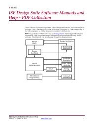
Chapter 2Product SpecificationThe <strong>Xilinx</strong>® 7 <strong>Series</strong> <strong>FPGAs</strong> <strong>Integrated</strong> <strong>Block</strong> <strong>for</strong> <strong>PCI</strong> <strong>Express</strong>® contains full support <strong>for</strong>2.5 Gb/s and 5.0 Gb/s <strong>PCI</strong> <strong>Express</strong> Endpoint and Root Port configurations. For 8.0 Gb/s(Gen3) support, see Virtex-7 FPGA Gen3 <strong>Integrated</strong> <strong>Block</strong> <strong>for</strong> <strong>PCI</strong> <strong>Express</strong> Product Guide[Ref 3], <strong>for</strong> device support and in<strong>for</strong>mation on the Virtex®-7 FPGA Gen3 <strong>Integrated</strong> <strong>Block</strong><strong>for</strong> <strong>PCI</strong> <strong>Express</strong>.Table 2-1 defines the <strong>Integrated</strong> <strong>Block</strong> <strong>for</strong> <strong>PCI</strong>e® solutions.Table 2-1:Product OverviewThe LogiCORE IP 7 <strong>Series</strong> <strong>FPGAs</strong> <strong>Integrated</strong> <strong>Block</strong> <strong>for</strong> <strong>PCI</strong> <strong>Express</strong> core internallyinstantiates the 7 <strong>Series</strong> <strong>FPGAs</strong> <strong>Integrated</strong> <strong>Block</strong> <strong>for</strong> <strong>PCI</strong> <strong>Express</strong> (<strong>PCI</strong>E_2_1). The integratedblock follows the <strong>PCI</strong> <strong>Express</strong> Base Specification layering model, which consists of thePhysical, Data Link, and Transaction layers. The integrated block is compliant with the<strong>PCI</strong> <strong>Express</strong> Base Specification, rev. 2.1 [Ref 2].Figure 2-1 illustrates these interfaces to the 7 <strong>Series</strong> <strong>FPGAs</strong> <strong>Integrated</strong> <strong>Block</strong> <strong>for</strong> <strong>PCI</strong> <strong>Express</strong>core:• System (SYS) interfaceProduct Name User Interface Width Supported Lane Widths1-lane at 2.5 Gb/s, 5.0 Gb/s 64 x12-lane at 2.5 Gb/s, 5.0 Gb/s 64 x1, x2 (1)4-lane at 2.5 Gb/s, 5.0 Gb/s 64, 128 x1, x2, x4 (1),(2)8-lane at 2.5 Gb/s, 5.0 Gb/s 64, 128 x1, x2, x4, x8 (1),(3)Notes:1. See Link Training: 2-Lane, 4-Lane, and 8-Lane Components, page 146 <strong>for</strong> additional in<strong>for</strong>mation.2. The x4 at 2.5 Gb/s option in the CORE Generator tool provides only the 64-bit width interface.3. x8 at 5.0 Gb/s only available in the 128-bit width.• <strong>PCI</strong> <strong>Express</strong> (<strong>PCI</strong>_EXP) interface• Configuration (CFG) interface• Transaction interface (AXI4-Stream)• Physical Layer Control and Status (PL) interface7 <strong>Series</strong> <strong>Integrated</strong> <strong>Block</strong> <strong>for</strong> <strong>PCI</strong>e (v1.6) www.xilinx.com 11<strong>PG054</strong> July 25, 2012Product Specification
Standards ComplianceThe core uses packets to exchange in<strong>for</strong>mation between the various modules. Packets are<strong>for</strong>med in the Transaction and Data Link Layers to carry in<strong>for</strong>mation from the transmittingcomponent to the receiving component. Necessary in<strong>for</strong>mation is added to the packetbeing transmitted, which is required to handle the packet at those layers. At the receivingend, each layer of the receiving element processes the incoming packet, strips the relevantin<strong>for</strong>mation and <strong>for</strong>wards the packet to the next layer.As a result, the received packets are trans<strong>for</strong>med from their Physical Layer representation totheir Data Link Layer representation and the Transaction Layer representation.X-Ref Target - Figure 2-1LogiCORE IP 7 <strong>Series</strong> <strong>FPGAs</strong><strong>Integrated</strong> <strong>Block</strong> <strong>for</strong> <strong>PCI</strong> <strong>Express</strong>TX<strong>Block</strong> RAMRX<strong>Block</strong> RAMUserLogicAXI4-StreamInterfacePhysical LayerControl and StatusHostInterfacePhysical(PL)Configuration(CFG)7 <strong>Series</strong> <strong>FPGAs</strong><strong>Integrated</strong> <strong>Block</strong> <strong>for</strong><strong>PCI</strong> <strong>Express</strong>(<strong>PCI</strong>E_2_1)Transceivers<strong>PCI</strong> <strong>Express</strong>(<strong>PCI</strong>_EXP)Optional Debug<strong>PCI</strong><strong>Express</strong>FabricUser LogicUserLogicOptional Debug(DRP)System(SYS)ClockandResetFigure 2-1:Top-Level Functional <strong>Block</strong>s and InterfacesStandards ComplianceThe 7 <strong>Series</strong> <strong>FPGAs</strong> <strong>Integrated</strong> <strong>Block</strong> <strong>for</strong> <strong>PCI</strong> <strong>Express</strong> is compliant with the <strong>PCI</strong> <strong>Express</strong> BaseSpecification, rev. 2.1 [Ref 2].Resource UtilizationTable 2-2 shows the resources <strong>for</strong> the 7 series <strong>FPGAs</strong> <strong>Integrated</strong> <strong>Block</strong> <strong>for</strong> <strong>PCI</strong> <strong>Express</strong> core<strong>for</strong> ISE® Design Suite implementations.7 <strong>Series</strong> <strong>Integrated</strong> <strong>Block</strong> <strong>for</strong> <strong>PCI</strong>e (v1.6) www.xilinx.com 12<strong>PG054</strong> July 25, 2012Product Specification
Minimum Device RequirementsTable 2-2:Resources UsedProductInterfaceWidthGTXE1 LUT (1) FF (1) RX BuffersSize (KB)TX BuffersSize (KB)CMPS (2)(Bytes)<strong>Block</strong>RAMMMCMsClockBuffers1-lane Gen1/Gen2 (3) 64-bit 1 400 5752-lane Gen1/Gen264-bit 2 525 7504-lane Gen1 64-bit 4 800 11004-lane Gen264-bit,128-bit4 800 13008 or 16 4-32 128-1024 2-16 1 58-lane, Gen164-bit,128-bit8 1350 22758-lane, Gen2 128-bit 8 1450 2600Notes:1. Numbers are <strong>for</strong> the default core configuration. Actual LUT and FF utilization values vary based on specific configurations.2. Capability Maximum Payload Size (CMPS).3. Gen1 speeds are 2.5 Gb/s. Gen2 speeds are 5.0 Gb/s.Minimum Device RequirementsTable 2-3 lists the minimum device requirements <strong>for</strong> 7 series <strong>FPGAs</strong> <strong>Integrated</strong> <strong>Block</strong> <strong>for</strong> <strong>PCI</strong><strong>Express</strong> configurations.Table 2-3:7 <strong>Series</strong> <strong>FPGAs</strong> <strong>Integrated</strong> <strong>Block</strong> <strong>for</strong> <strong>PCI</strong> <strong>Express</strong> ConfigurationsArtix-7<strong>FPGAs</strong> (1) Kintex-7 <strong>FPGAs</strong> Virtex-7 <strong>FPGAs</strong>XC7A100TXC7A200TXC7A350TXC7K480TXC7K420XC7K410TXC7K355TXC7K325TXCK7160T (2)XC7K70T (2) XC7VX485T XC7V585T XC7V1500T (3) XC7V2000T (3)Number of <strong>Integrated</strong> <strong>Block</strong>s <strong>for</strong><strong>PCI</strong>e (see Table 2-4)1 1 4 3 3 4Gen1 (2.5 Gb/s) 1–4 1–8 1–8 1–8 1–8 1–8LanesGen2 (5.0 Gb/s) 1–4 1–8 1–8 1–8 1–8 1–8Gen3 (8.0 Gb/s) (4) — — — — — —x1–x4 Gen1-1, -2, -3,-2L-1, -2, -3, -2L -1, -2, -3, -2L -1, -2, -3, -2L -1, -2, -2L -1, -2, -2LSpeed Gradex8 Gen1 NA -1, -2, -3, -2L -1, -2, -3, -2L -1, -2, -3, -2L -1, -2, -2L -1, -2, -2Lx1–x4 Gen2 -2, -3 -1, -2, -3, -2L -1, -2, -3, -2L -1, -2, -3, -2L -1, -2, -2L -1, -2, -2Lx8 Gen2 NA -2, -3, -2L (1V) -2, -3, -2L (1V) -2, -3, -2L (1V) -2, -2L (1V) -2, -2L (1V)7 <strong>Series</strong> <strong>Integrated</strong> <strong>Block</strong> <strong>for</strong> <strong>PCI</strong>e (v1.6) www.xilinx.com 13<strong>PG054</strong> July 25, 2012Product Specification
Available <strong>Integrated</strong> <strong>Block</strong>s <strong>for</strong> <strong>PCI</strong>eTable 2-3:7 <strong>Series</strong> <strong>FPGAs</strong> <strong>Integrated</strong> <strong>Block</strong> <strong>for</strong> <strong>PCI</strong> <strong>Express</strong> Configurations (Cont’d)Artix-7<strong>FPGAs</strong> (1) Kintex-7 <strong>FPGAs</strong> Virtex-7 <strong>FPGAs</strong>XC7A100TXC7A200TXC7A350TXC7K480TXC7K420XC7K410TXC7K355TXC7K325TXCK7160T (2)XC7K70T (2) XC7VX485T XC7V585T XC7V1500T (3) XC7V2000T (3)MaximumPayload SizeMPS (Bytes)Gen1 1024 1024 1024 1024 1024 1024x1–x4 Gen2 1024 1024 1024 1024 1024 1024x8 Gen2NA512 (-3)256 (-2, -2L)512 (-3)256 (-2, -2L)512 (-3)256 (-2, -2L)512 (-3)256 (-2, -2L)512 (-3)256 (-2, -2L)Notes:1. Artix-7 devices only support x1, x2, and x4 operation.2. Kintex-7 FPGA FBG484 packages only support x1, x2, and x4 operation.3. XC7V1500T and XC7V2000T are available in the Vivado tool flow, but not available in the ISE tool flow.4. The 7 <strong>Series</strong> <strong>FPGAs</strong> <strong>Integrated</strong> <strong>Block</strong> <strong>for</strong> <strong>PCI</strong> <strong>Express</strong> does not support Gen3 operation. See Virtex-7 FPGA Gen3 <strong>Integrated</strong> <strong>Block</strong> <strong>for</strong><strong>PCI</strong> <strong>Express</strong> Product Guide [Ref 3], <strong>for</strong> device support and in<strong>for</strong>mation on the Virtex-7 FPGA Gen3 <strong>Integrated</strong> <strong>Block</strong> <strong>for</strong> <strong>PCI</strong> <strong>Express</strong>.Available <strong>Integrated</strong> <strong>Block</strong>s <strong>for</strong> <strong>PCI</strong>eTable 2-4 lists which 7 series <strong>Integrated</strong> <strong>Block</strong>s are available <strong>for</strong> use in <strong>FPGAs</strong> containingmultiple blocks. In some cases, not all blocks can be targeted due to lack of bondedtransceiver sites adjacent to the <strong>Integrated</strong> <strong>Block</strong>.Table 2-4: Available <strong>Integrated</strong> <strong>Block</strong>s <strong>for</strong> <strong>PCI</strong>eDevice Selection<strong>Integrated</strong> <strong>Block</strong> <strong>for</strong> <strong>PCI</strong>e LocationDevice Package X0Y0 X0Y1 X0Y2 X1Y0 X1Y1XC7VX485TFFG1157FFG1761FFG1930FFG1158FFG19273 33 3 3 3XC7V585TFFG1157 3 3FFG1761 3 3 3XC7V1500T FLG1761 3 3 3XC7V2000TFHG1761 3 3 3FLG1926 3 37 <strong>Series</strong> <strong>Integrated</strong> <strong>Block</strong> <strong>for</strong> <strong>PCI</strong>e (v1.6) www.xilinx.com 14<strong>PG054</strong> July 25, 2012Product Specification
Core InterfacesCore InterfacesThe 7 <strong>Series</strong> <strong>FPGAs</strong> <strong>Integrated</strong> <strong>Block</strong> <strong>for</strong> <strong>PCI</strong> <strong>Express</strong> core includes top-level signal interfacesthat have sub-groups <strong>for</strong> the receive direction, transmit direction, and signals common toboth directions.System InterfaceThe System (SYS) interface consists of the system reset signal (sys_reset) and the systemclock signal (sys_clk), as described in Table 2-5.Table 2-5: System Interface SignalsFunction Signal Name Direction DescriptionSystem Reset sys_reset Input Asynchronous signal. sys_reset must beasserted <strong>for</strong> at least 1500 ns during poweron and warm reset operations.System Clock sys_clk Input Reference clock: Selectable frequency100 MHz, 125 MHz, or 250 MHz.Some 7 series devices do not have 3.3 V I/Os available. There<strong>for</strong>e the appropriate level shiftis required to operate with these devices that contain only 1.8 V banks.The system reset signal is an asynchronous input. The assertion of sys_reset causes ahard reset of the entire core. The reset provided by the <strong>PCI</strong> <strong>Express</strong> system is typically activeLow (<strong>for</strong> example, PERST#) and needs to be inverted be<strong>for</strong>e connecting to the sys_resetsignal. The system reset signal is a 3.3 V signal.The system input clock must be 100 MHz, 125 MHz, or 250 MHz, as selected in theCORE Generator tool GUI Clock and Reference signals.<strong>PCI</strong> <strong>Express</strong> InterfaceThe <strong>PCI</strong> <strong>Express</strong> (<strong>PCI</strong>_EXP) interface consists of differential transmit and receive pairsorganized in multiple lanes. A <strong>PCI</strong> <strong>Express</strong> lane consists of a pair of transmit differentialsignals (pci_exp_txp, pci_exp_txn) and a pair of receive differential signals{pci_exp_rxp, pci_exp_rxn}. The 1-lane core supports only Lane 0, the 2-lane coresupports lanes 0-1, the 4-lane core supports lanes 0-3, and the 8-lane core supports lanes0-7. Transmit and receive signals of the <strong>PCI</strong>_EXP interface are defined in Table 2-6.7 <strong>Series</strong> <strong>Integrated</strong> <strong>Block</strong> <strong>for</strong> <strong>PCI</strong>e (v1.6) www.xilinx.com 15<strong>PG054</strong> July 25, 2012Product Specification
Core InterfacesTable 2-6:LaneNumber1-Lane Cores<strong>PCI</strong> <strong>Express</strong> Interface Signals <strong>for</strong> 1-, 2-, 4- and 8-Lane CoresName Direction Description0 pci_exp_txp0 Output <strong>PCI</strong> <strong>Express</strong> Transmit Positive: Serial Differential Output 0 (+)2-Lane Corespci_exp_txn0 Output <strong>PCI</strong> <strong>Express</strong> Transmit Negative: Serial Differential Output 0 (–)pci_exp_rxp0 Input <strong>PCI</strong> <strong>Express</strong> Receive Positive: Serial Differential Input 0 (+)pci_exp_rxn0 Input <strong>PCI</strong> <strong>Express</strong> Receive Negative: Serial Differential Input 0 (–)0 pci_exp_txp0 Output <strong>PCI</strong> <strong>Express</strong> Transmit Positive: Serial Differential Output 0 (+)pci_exp_txn0 Output <strong>PCI</strong> <strong>Express</strong> Transmit Negative: Serial Differential Output 0 (–)pci_exp_rxp0 Input <strong>PCI</strong> <strong>Express</strong> Receive Positive: Serial Differential Input 0 (+)pci_exp_rxn0 Input <strong>PCI</strong> <strong>Express</strong> Receive Negative: Serial Differential Input 0 (–)1 pci_exp_txp1 Output <strong>PCI</strong> <strong>Express</strong> Transmit Positive: Serial Differential Output 1 (+)4-Lane Corespci_exp_txn1 Output <strong>PCI</strong> <strong>Express</strong> Transmit Negative: Serial Differential Output 1 (–)pci_exp_rxp1 Input <strong>PCI</strong> <strong>Express</strong> Receive Positive: Serial Differential Input 1 (+)pci_exp_rxn1 Input <strong>PCI</strong> <strong>Express</strong> Receive Negative: Serial Differential Input 1 (–)0 pci_exp_txp0 Output <strong>PCI</strong> <strong>Express</strong> Transmit Positive: Serial Differential Output 0 (+)pci_exp_txn0 Output <strong>PCI</strong> <strong>Express</strong> Transmit Negative: Serial Differential Output 0 (–)pci_exp_rxp0 Input <strong>PCI</strong> <strong>Express</strong> Receive Positive: Serial Differential Input 0 (+)pci_exp_rxn0 Input <strong>PCI</strong> <strong>Express</strong> Receive Negative: Serial Differential Input 0 (–)1 pci_exp_txp1 Output <strong>PCI</strong> <strong>Express</strong> Transmit Positive: Serial Differential Output 1 (+)pci_exp_txn1 Output <strong>PCI</strong> <strong>Express</strong> Transmit Negative: Serial Differential Output 1 (–)pci_exp_rxp1 Input <strong>PCI</strong> <strong>Express</strong> Receive Positive: Serial Differential Input 1 (+)pci_exp_rxn1 Input <strong>PCI</strong> <strong>Express</strong> Receive Negative: Serial Differential Input 1 (–)2 pci_exp_txp2 Output <strong>PCI</strong> <strong>Express</strong> Transmit Positive: Serial Differential Output 2 (+)pci_exp_txn2 Output <strong>PCI</strong> <strong>Express</strong> Transmit Negative: Serial Differential Output 2 (–)pci_exp_rxp2 Input <strong>PCI</strong> <strong>Express</strong> Receive Positive: Serial Differential Input 2 (+)pci_exp_rxn2 Input <strong>PCI</strong> <strong>Express</strong> Receive Negative: Serial Differential Input 2 (–)3 pci_exp_txp3 Output <strong>PCI</strong> <strong>Express</strong> Transmit Positive: Serial Differential Output 3 (+)pci_exp_txn3 Output <strong>PCI</strong> <strong>Express</strong> Transmit Negative: Serial Differential Output 3 (–)pci_exp_rxp3 Input <strong>PCI</strong> <strong>Express</strong> Receive Positive: Serial Differential Input 3 (+)pci_exp_rxn3 Input <strong>PCI</strong> <strong>Express</strong> Receive Negative: Serial Differential Input 3 (–)7 <strong>Series</strong> <strong>Integrated</strong> <strong>Block</strong> <strong>for</strong> <strong>PCI</strong>e (v1.6) www.xilinx.com 16<strong>PG054</strong> July 25, 2012Product Specification
Core InterfacesTable 2-6:LaneNumber8-Lane Cores<strong>PCI</strong> <strong>Express</strong> Interface Signals <strong>for</strong> 1-, 2-, 4- and 8-Lane Cores (Cont’d)Name Direction Description0 pci_exp_txp0 Output <strong>PCI</strong> <strong>Express</strong> Transmit Positive: Serial Differential Output 0 (+)pci_exp_txn0 Output <strong>PCI</strong> <strong>Express</strong> Transmit Negative: Serial Differential Output 0 (–)pci_exp_rxp0 Input <strong>PCI</strong> <strong>Express</strong> Receive Positive: Serial Differential Input 0 (+)pci_exp_rxn0 Input <strong>PCI</strong> <strong>Express</strong> Receive Negative: Serial Differential Input 0 (–)1 pci_exp_txp1 Output <strong>PCI</strong> <strong>Express</strong> Transmit Positive: Serial Differential Output 1 (+)pci_exp_txn1 Output <strong>PCI</strong> <strong>Express</strong> Transmit Negative: Serial Differential Output 1 (–)pci_exp_rxp1 Input <strong>PCI</strong> <strong>Express</strong> Receive Positive: Serial Differential Input 1 (+)pci_exp_rxn1 Input <strong>PCI</strong> <strong>Express</strong> Receive Negative: Serial Differential Input 1 (–)2 pci_exp_txp2 Output <strong>PCI</strong> <strong>Express</strong> Transmit Positive: Serial Differential Output 2 (+)pci_exp_txn2 Output <strong>PCI</strong> <strong>Express</strong> Transmit Negative: Serial Differential Output 2 (–)pci_exp_rxp2 Input <strong>PCI</strong> <strong>Express</strong> Receive Positive: Serial Differential Input 2 (+)pci_exp_rxn2 Input <strong>PCI</strong> <strong>Express</strong> Receive Negative: Serial Differential Input 2 (–)3 pci_exp_txp3 Output <strong>PCI</strong> <strong>Express</strong> Transmit Positive: Serial Differential Output 3 (+)pci_exp_txn3 Output <strong>PCI</strong> <strong>Express</strong> Transmit Negative: Serial Differential Output 3 (–)pci_exp_rxp3 Input <strong>PCI</strong> <strong>Express</strong> Receive Positive: Serial Differential Input 3 (+)pci_exp_rxn3 Input <strong>PCI</strong> <strong>Express</strong> Receive Negative: Serial Differential Input 3 (–)4 pci_exp_txp4 Output <strong>PCI</strong> <strong>Express</strong> Transmit Positive: Serial Differential Output 4 (+)pci_exp_txn4 Output <strong>PCI</strong> <strong>Express</strong> Transmit Negative: Serial Differential Output 4 (–)pci_exp_rxp4 Input <strong>PCI</strong> <strong>Express</strong> Receive Positive: Serial Differential Input 4 (+)pci_exp_rxn4 Input <strong>PCI</strong> <strong>Express</strong> Receive Negative: Serial Differential Input 4 (–)5 pci_exp_txp5 Output <strong>PCI</strong> <strong>Express</strong> Transmit Positive: Serial Differential Output 5 (+)pci_exp_txn5 Output <strong>PCI</strong> <strong>Express</strong> Transmit Negative: Serial Differential Output 5 (–)pci_exp_rxp5 Input <strong>PCI</strong> <strong>Express</strong> Receive Positive: Serial Differential Input 5 (+)pci_exp_rxn5 Input <strong>PCI</strong> <strong>Express</strong> Receive Negative: Serial Differential Input 5 (–)6 pci_exp_txp6 Output <strong>PCI</strong> <strong>Express</strong> Transmit Positive: Serial Differential Output 6 (+)pci_exp_txn6 Output <strong>PCI</strong> <strong>Express</strong> Transmit Negative: Serial Differential Output 6 (–)pci_exp_rxp6 Input <strong>PCI</strong> <strong>Express</strong> Receive Positive: Serial Differential Input 6 (+)pci_exp_rxn6 Input <strong>PCI</strong> <strong>Express</strong> Receive Negative: Serial Differential Input 6 (–)7 pci_exp_txp7 Output <strong>PCI</strong> <strong>Express</strong> Transmit Positive: Serial Differential Output 7 (+)pci_exp_txn7 Output <strong>PCI</strong> <strong>Express</strong> Transmit Negative: Serial Differential Output 7 (–)pci_exp_rxp7 Input <strong>PCI</strong> <strong>Express</strong> Receive Positive: Serial Differential Input 7 (+)pci_exp_rxn7 Input <strong>PCI</strong> <strong>Express</strong> Receive Negative: Serial Differential Input 7 (–)7 <strong>Series</strong> <strong>Integrated</strong> <strong>Block</strong> <strong>for</strong> <strong>PCI</strong>e (v1.6) www.xilinx.com 17<strong>PG054</strong> July 25, 2012Product Specification
Transaction InterfaceTransaction InterfaceThe Transaction interface provides a mechanism <strong>for</strong> the user design to generate andconsume TLPs. The signal names and signal descriptions <strong>for</strong> this interface are shown inTable 2-7, Table 2-9, and Table 2-10.Common InterfaceTable 2-7 describes the common interface signals.Table 2-7: Common Transaction Interface SignalsName Direction Descriptionuser_clk_out Output Transaction Clock: Transaction, Configuration, and Physical LayerControl and Status Interface operations are referenced to andsynchronous with the rising edge of this clock. This signal is activeafter power-on, and sys_reset has no effect on it. This signal isguaranteed to be stable at the selected operating frequency onlyafter user_reset_out is deasserted. The user_clk_out clock outputis a fixed frequency configured in the CORE Generator tool. Thissignal does not change frequencies in case of link recovery ortraining down.See Table 2-8 <strong>for</strong> recommended and optional frequencies.user_reset_out Output Transaction Reset: User logic interacting with the Transaction andConfiguration interfaces must use user_reset_out to return to itsquiescent state. This signal is deasserted synchronously with respectto user_clk_out, and is deasserted and asserted asynchronouslywith sys_reset assertion. This signal is asserted <strong>for</strong> core in-bandreset events such as Hot Reset or Link Disable.user_lnk_up Output Transaction Link Up: Transaction link-up is asserted when the coreand the connected upstream link partner port are ready and able toexchange data packets. Transaction link-up is deasserted when thecore and link partner are attempting to establish communication, orwhen communication with the link partner is lost due to errors onthe transmission channel. This signal is also deasserted when thecore is driven to Hot Reset or Link Disable state by the link partner,and all TLPs stored in the core are lost. This signal is not deassertedwhile in the Recovery state, but is deasserted if Recovery fails.fc_ph[7:0] Output Posted Header Flow Control Credits: The number of Posted HeaderFC credits <strong>for</strong> the selected flow control type.fc_pd[11:0] Output Posted Data Flow Control Credits: The number of Posted Data FCcredits <strong>for</strong> the selected flow control type.fc_nph[7:0] Output Non-Posted Header Flow Control Credits: The number ofNon-Posted Header FC credits <strong>for</strong> the selected flow control type.fc_npd[11:0] Output Non-Posted Data Flow Control Credits: The number of Non-PostedData FC credits <strong>for</strong> the selected flow control type.7 <strong>Series</strong> <strong>Integrated</strong> <strong>Block</strong> <strong>for</strong> <strong>PCI</strong>e (v1.6) www.xilinx.com 18<strong>PG054</strong> July 25, 2012Product Specification
Transaction InterfaceTable 2-7:Common Transaction Interface Signals (Cont’d)Name Direction Descriptionfc_cplh[7:0] Output Completion Header Flow Control Credits: The number of CompletionHeader FC credits <strong>for</strong> the selected flow control type.fc_cpld[11:0] Output Completion Data Flow Control Credits: The number of CompletionData FC credits <strong>for</strong> the selected flow control type.fc_sel[2:0] Input Flow Control In<strong>for</strong>mational Select: Selects the type of flow controlin<strong>for</strong>mation presented on the fc_* signals. Possible values:• 000: Receive buffer available space• 001: Receive credits granted to the link partner• 010: Receive credits consumed• 100: Transmit user credits available• 101: Transmit credit limit• 110: Transmit credits consumedTable 2-8:ProductRecommended and Optional Transaction Clock (user_clk_out) FrequenciesTransmit InterfaceLink Speed(Gb/s)Interface Width (1)(Bits)RecommendedFrequency (MHz)OptionalFrequency (MHz)1-lane 2.5 64 62.5 31.25, 125, 2501-lane 5 64 62.5 125, 2502-lane 2.5 64 62.5 125, 2502-lane 5 64 125 2504-lane 2.5 64 125 2504-lane 5 64 250 -4-lane 5 128 125 2508-lane 2.5 64 250 -8-lane 2.5 128 125 2508-lane 5 128 250 -Notes:1. Interface Width is a static selection and does not change with dynamic Link Speed changes.Table 2-9 defines the transmit (TX) interface signals. The bus s_axis_tx_tuser consists ofunrelated signals. Both the mnemonics and TSUSER signals are used throughout thisdocument. For example, the Transmit Source Discontinue signal is referenced as:(tsrc_dsc)s_axis_tx_tuser[3].7 <strong>Series</strong> <strong>Integrated</strong> <strong>Block</strong> <strong>for</strong> <strong>PCI</strong>e (v1.6) www.xilinx.com 19<strong>PG054</strong> July 25, 2012Product Specification
Transaction InterfaceTable 2-9: Transmit Interface SignalsName Mnemonic Direction Descriptions_axis_tx_tlast Input Transmit End-of-Frame (EOF): Signals the end of a packet.Valid only along with assertion of s_axis_tx_tvalid.s_axis_tx_tdata[W-1:0] Input Transmit Data: Packet data to be transmitted.s_axis_tx_tkeep[7:0](64-bit interface)s_axis_tx_tkeep[15:0](128-bit interface)InputProductData Bus Width(W)1-lane (2.5 Gb/s and 5.0 Gb/s) 642-lane (2.5 Gb/s and 5.0 Gb/s) 644-lane (2.5 Gb/s and 5.0 Gb/s) 64 or 1288-lane (2.5 Gb/s and 5.0 Gb/s) 64 or 128Transmit Data Strobe: Determines which data bytes arevalid on s_axis_tx_tdata[W-1:0] during a given beat(s_axis_tx_tvalid and s_axis_tx_tready both asserted).Bit 0 corresponds to the least significant byte ons_axis_tx_tdata and bit 7 (64-bit) and bit 15(128-bit)correspond to the most significant byte, <strong>for</strong> example:• s_axis_tx_tkeep[0] == 1b, s_axis_tx_tdata[7:0] is valid• s_axis_tx_tkeep[7] ==0b, s_axis_tx_tdata[63:56] is notvalidWhen s_axis_tx_tlast is not asserted, the only valid valuesare 0xFF (64-bit) or 0xFFFF (128-bit).When s_axis_tx_tlast is asserted, valid values are:• 64-bit: only 0x0F and 0xFF are valid• 128-bit: 0x000F, 0x00FF, 0x0FFF, and 0xFFFF arevalids_axis_tx_tvalid Input Transmit Source Ready: Indicates that the UserApplication is presenting valid data on s_axis_tx_tdata.s_axis_tx_tready Output Transmit Destination Ready: Indicates that the core isready to accept data on s_axis_tx_tdata. The simultaneousassertion of s_axis_tx_tvalid and s_axis_tx_tready marksthe successful transfer of one data beat ons_axis_tx_tdata.s_axis_tx_tuser[3] t_src_dsc Input Transmit Source Discontinue: Can be asserted any timestarting on the first cycle after SOF. Assert s_axis_tx_tlastsimultaneously with (tx_src_dsc)s_axis_tx_tuser[3].tx_buf_av[5:0] Output Transmit Buffers Available: Indicates the number of freetransmit buffers available in the core. Each free transmitbuffer can accommodate one TLP up to the supportedMaximum Payload Size (MPS). The maximum number oftransmit buffers is determined by the supported MPS andblock RAM configuration selected. (See Core Bufferingand Flow Control, page 97.)tx_err_drop Output Transmit Error Drop: Indicates that the core discarded apacket because of a length violation or, when streaming,data was not presented on consecutive clock cycles.7 <strong>Series</strong> <strong>Integrated</strong> <strong>Block</strong> <strong>for</strong> <strong>PCI</strong>e (v1.6) www.xilinx.com 20<strong>PG054</strong> July 25, 2012Product Specification
Transaction InterfaceTable 2-9: Transmit Interface Signals (Cont’d)Name Mnemonic Direction Descriptions_axis_tx_tuser[2] tx_str Input Transmit Streamed: Indicates a packet is presented onconsecutive clock cycles and transmission on the link canbegin be<strong>for</strong>e the entire packet has been written to thecore. Commonly referred as transmit cut-through mode.tx_cfg_req Output Transmit Configuration Request: Asserted when the coreis ready to transmit a Configuration Completion or otherinternally generated TLP.tx_cfg_gnt Input Transmit Configuration Grant: Asserted by the UserApplication in response to tx_cfg_req, to allow the core totransmit an internally generated TLP. The tx_cfg_reqsignal is always deasserted after the core-generatedpacket has been serviced be<strong>for</strong>e another request is made.There<strong>for</strong>e, user designs can look <strong>for</strong> the rising edge oftx_cfg_req to determine when to assert tx_cfg_gnt.Holding tx_cfg_gnt deasserted after tx_cfg_req allowsuser-initiated TLPs to be given a higher priority oftransmission over core-generated TLPs. Assertingtx_cfg_gnt <strong>for</strong> one clock cycle when tx_cfg_req is assertedcauses the next packet output to be the core’s internallygenerated packet. In cases where there is no buffer spaceto store the internal packet, tx_cfg_req remains assertedeven after tx_cfg_gnt has been asserted. The user designdoes not need to assert tx_cfg_gnt again because theinitial assertion has been captured.If the user does not wish to alter the prioritization of thetransmission of internally generated TLPs, this signal canbe continuously asserted.s_axis_tx_tuser[1] tx_err_fwd Input Transmit Error Forward: This input marks the currentpacket in progress as error-poisoned. It can be assertedany time between SOF and EOF, inclusive. The tx_err_fwdsignal must not be asserted if (tx_str)s_axis_tx_tuser[2] isasserted.s_axis_tx_tuser[0] tx_ecrc_gen Input Transmit ECRC Generate: Causes the end-to-end cyclicredundancy check (ECRC) digest to be appended. Thisinput must be asserted at the beginning of the TLP.Receive InterfaceTable 2-10 defines the receive (RX) interface signals. The bus m_axis_tx_tuser consistsof unrelated signals. Mnemonics <strong>for</strong> these signals are used throughout this document inplace of the TUSER signal names.7 <strong>Series</strong> <strong>Integrated</strong> <strong>Block</strong> <strong>for</strong> <strong>PCI</strong>e (v1.6) www.xilinx.com 21<strong>PG054</strong> July 25, 2012Product Specification
Transaction InterfaceTable 2-10: Receive Interface SignalsName Mnemonic Direction Descriptionm_axis_rx_tlast Output Receive End-of-Frame (EOF): Signals the end of apacket. Valid only if m_axis_rx_tvalid is alsoasserted.m_axis_rx_tdata[W-1:0] Output Receive Data: Packet data being received. Valid only ifm_axis_rx_tvalid is also asserted.ProductData Bus Width(W)1-lane (2.5 Gb/s and 5.0 Gb/s) 642-lane (2.5 Gb/s and 5.0 Gb/s) 644-lane (2.5 Gb/s and 5.0 Gb/s) 64 or 1288-lane (2.5 Gb/s and 5.0 Gb/s) 64 or 128128-bit interface only: Unlike the Transmit interfaces_axis_tx_tdata[127:0], received TLPs canbegin on either the upper QWORDm_axis_rx_tdata[127:64] or lower QWORDm_axis_rx_tdata[63:0] of the bus. See thedescription of is_sof and (rx_is_sof[4:0])m_axis_rx_tuser[14:10]m_axis_rx_tuser[21:17] <strong>for</strong> further explanation.m_axis_rx_tkeep[7:0](64-bit interface only)OutputReceive Data Strobe:Determines which data bytes are valid onm_axis_rx_tdata[63:0] during a given beat(m_axis_rx_tvalid and m_axis_rx_treadyboth asserted).Bit 0 corresponds to the least significant byte onm_axis_rx_tdata and bit 7 correspond to the mostsignificant byte, <strong>for</strong> example:• m_axis_rx_tkeep[0] == 1b,m_axis_rx_tdata[7:0] is valid• m_axis_rx_tkeep[7] == 0b,m_axis_rx_tdata[63:56] is not validWhen m_axis_rx_tlast is not asserted, the onlyvalid value is 0xFF.When m_axis_rx_tlast is asserted, valid valuesare:• 64-bit:, only 0x0F and 0xFF are valid7 <strong>Series</strong> <strong>Integrated</strong> <strong>Block</strong> <strong>for</strong> <strong>PCI</strong>e (v1.6) www.xilinx.com 22<strong>PG054</strong> July 25, 2012Product Specification
Transaction InterfaceTable 2-10: Receive Interface Signals (Cont’d)Name Mnemonic Direction Descriptionm_axis_rx_tuser[14:10](128-bit interface only)m_axis_rx_tuser[21:17](128-bit interface only)rx_is_sof[4:0] Output Indicates the start of a new packet header inm_axis_rx_tdata:Bit 4: Asserted when a new packet is presentBit 0-3: Indicates byte location of start of new packet,binary encodedValid values:• 5'b10000 = SOF at AXI byte 0 (DWORD 0)m_axis_rx_tdata[7:0]• 5'b11000 = SOF at AXI byte 8 (DWORD 2)m_axis_rx_tdata[71:64]• 5'b00000 = No SOF presentrx_is_eof[4:0] Output Indicates the end of a packet in m_axis_rx_tdata:Bit 4: Asserted when a packet is endingBit 0-3: Indicates byte location of end of the packet,binary encodedValid values:• 5'b10011 = EOF at AXI byte 3 (DWORD 0)m_axis_rx_tdata[31:24]• 5'b10111 = EOF at AXI byte 7 (DWORD 1)m_axis_rx_tdata[63:56]• 5'b11011 = EOF at AXI byte 11 (DWORD 2)m_axis_rx_tdata[95:88]• 5'b11111 = EOF at AXI byte 15 (DWORD 3)m_axis_rx_tdata[127:120]• 5'b00011 = No EOF presentm_axis_rx_tuser[1] rx_err_fwd Output Receive Error Forward:64-bit interface: When asserted, marks the packet inprogress as error-poisoned. Asserted by the core <strong>for</strong>the entire length of the packet.128-bit interface: When asserted, marks the currentpacket in progress as error-poisoned. Asserted by thecore <strong>for</strong> the entire length of the packet. If assertedduring a straddled data transfer, applies to the packetthat is beginning.m_axis_rx_tuser[0] rx_ecrc_err Output Receive ECRC Error: Indicates the current packet hasan ECRC error. Asserted at the packet EOF.m_axis_rx_tvalid Output Receive Source Ready: Indicates that the core ispresenting valid data on m_axis_rx_tdata.m_axis_rx_tready Input Receive Destination Ready: Indicates that the UserApplication is ready to accept data onm_axis_rx_tdata. The simultaneous assertion ofm_axis_rx_tvalid and m_axis_rx_treadymarks the successful transfer of one data beat ons_axis_tx_tdata.7 <strong>Series</strong> <strong>Integrated</strong> <strong>Block</strong> <strong>for</strong> <strong>PCI</strong>e (v1.6) www.xilinx.com 23<strong>PG054</strong> July 25, 2012Product Specification
Transaction InterfaceTable 2-10: Receive Interface Signals (Cont’d)Name Mnemonic Direction Descriptionrx_np_ok Input Receive Non-Posted OK: The User Application assertsthis signal when it is ready to accept Non-PostedRequest TLPs. rx_np_ok must be deasserted whenthe User Application cannot process receivedNon-Posted TLPs, so that these can be buffered withinthe core's receive queue. In this case, Posted andCompletion TLPs received after the Non-Posted TLPsbypass the blocked TLPs.When the User Application approaches a state whereit is unable to service Non-Posted Requests, it mustdeassert rx_np_ok two clock cycle be<strong>for</strong>e the coreasserts m_axis_rx_tlast of the next-to-lastNon-Posted TLP the User Application can accept.rx_np_req Input Receive Non-Posted Request: When asserted,requests one non-posted TLP from the core peruser_clk cycle. If the User Application can processreceived Non-Posted TLPs at the line rate, this signalcan be constantly asserted. If the User Application isnot requesting Non-Posted packets, received Postedand Completion TLPs bypass waiting Non-PostedTLPs.m_axis_rx_tuser[9:2] rx_bar_hit[7:0] Output Receive BAR Hit: Indicates BAR(s) targeted by thecurrent receive transaction. Asserted from thebeginning of the packet to m_axis_rx_tlast.• (rx_bar_hit[0])m_axis_rx_tuser[2]: BAR0• (rx_bar_hit[1])m_axis_rx_tuser[3]: BAR1• (rx_bar_hit[2])m_axis_rx_tuser[4]: BAR2• (rx_bar_hit[3])m_axis_rx_tuser[5]: BAR3• (rx_bar_hit[4])m_axis_rx_tuser[6]: BAR4• (rx_bar_hit[5])m_axis_rx_tuser[7]: BAR5• (rx_bar_hit[6])m_axis_rx_tuser[8]:Expansion ROM AddressIf two BARs are configured into a single 64-bitaddress, both corresponding rx_bar_hit bits areasserted.m_axis_rx_tuser[8:4] are not applicable to RootPort configurations.m_axis_rx_tuser[9] is reserved <strong>for</strong> future use.m_axis_rx_tuser[16:15]Physical Layer InterfaceReservedThe Physical Layer (PL) interface enables the user design to inspect the status of the Linkand Link Partner and control the Link State. Table 2-11 describes the signals <strong>for</strong> the PLinterface.7 <strong>Series</strong> <strong>Integrated</strong> <strong>Block</strong> <strong>for</strong> <strong>PCI</strong>e (v1.6) www.xilinx.com 24<strong>PG054</strong> July 25, 2012Product Specification
Transaction InterfaceTable 2-11:Physical Layer Interface SignalsName Direction Descriptionpl_initial_link_width[2:0] Output Initial Negotiated Link Width: Indicates the linkwidth after the <strong>PCI</strong> <strong>Express</strong> port has achieved thefirst successful link training. Initial Negotiated LinkWidth represents the widest link width possibleduring normal operation of the link, and can beequal to or smaller than the capability link width(smaller of the two) supported by link partners. Thisvalue is reset when the core is reset or the LTSSMgoes through the Detect state. Otherwise the valueremains the same.• 000: Link not trained• 001: 1-Lane link• 010: 2-Lane link• 011: 4-Lane link• 100: 8-Lane linkpl_phy_lnk_up Output Physical Layer Link Up Status: Indicates the physicallayer link up status.pl_lane_reversal_mode[1:0] Output Lane Reversal Mode: Indicates the current LaneReversal mode.• 00: No reversal• 01: Lanes 1:0 reversed• 10: Lanes 3:0 reversed• 11: Lanes 7:0 reversedpl_link_gen2_cap Output Link Gen2 Capable: Indicates that the <strong>PCI</strong> <strong>Express</strong>link is 5.0 Gb/s (Gen 2) speed capable (both the LinkPartner and the Device are Gen 2 capable)• 0: Link is not Gen2 Capable• 1: Link is Gen2 Capablepl_link_partner_gen2_supported Output Link Partner Gen2 Capable: Indicates if the <strong>PCI</strong><strong>Express</strong> link partner advertises 5.0 Gb/s (Gen2)capability. Valid only when user_lnk_up isasserted.• 0: Link partner not Gen2 capable• 1: Link partner is Gen2 capablepl_link_upcfg_cap Output Link Upconfigure Capable: Indicates the <strong>PCI</strong> <strong>Express</strong>link is Upconfigure capable. Valid only whenuser_lnk_up is asserted.• 0: Link is not Upconfigure capable• 1: Link is Upconfigure capablepl_sel_lnk_rate Output Current Link Rate: Reports the current link speed.Valid only when user_lnk_up is asserted.0: 2.5 Gb/s1: 5.0 Gb/s7 <strong>Series</strong> <strong>Integrated</strong> <strong>Block</strong> <strong>for</strong> <strong>PCI</strong>e (v1.6) www.xilinx.com 25<strong>PG054</strong> July 25, 2012Product Specification
Transaction InterfaceTable 2-11:Physical Layer Interface Signals (Cont’d)Name Direction Descriptionpl_sel_lnk_width[1:0] Output Current Link Width: Reports the current link width.Valid only when user_lnk_up is asserted.00: 1-Lane link01: 2-Lane link10: 4-Lane link11: 8-Lane linkpl_ltssm_state[5:0] Output LTSSM State: Shows the current LTSSM state (hex).0, 1: Detect Quiet2, 3: Detect Active4: Polling Active5: Polling Configuration6: Polling Compliance, Pre_Send_EIOS7: Polling Compliance, Pre_Timeout8: Polling Compliance, Send_Pattern9: Polling Compliance, Post_Send_EIOSA: Polling Compliance, Post_TimeoutB: Configuration Linkwidth, State 0C: Configuration Linkwidth, State 1D: Configuration Linkwidth, Accept 0E: Configuration Linkwidth, Accept 1F: Configuration Lanenum Wait10: Configuration Lanenum, Accept11: Configuration Complete x112: Configuration Complete x213: Configuration Complete x414: Configuration Complete x815: Configuration Idle16: L017: L1 Entry018: L1 Entry119: L1 Entry2 (also used <strong>for</strong> the L2/L3 Ready pseudostate)1A: L1 Idle1B: L1 Exit1C: Recovery Rcvrlock1D: Recovery Rcvrcfg7 <strong>Series</strong> <strong>Integrated</strong> <strong>Block</strong> <strong>for</strong> <strong>PCI</strong>e (v1.6) www.xilinx.com 26<strong>PG054</strong> July 25, 2012Product Specification
Transaction InterfaceTable 2-11:Physical Layer Interface Signals (Cont’d)Name Direction Descriptionpl_ltssm_state[5:0] (Cont’d) Output 1E: Recovery Speed_01F: Recovery Speed_120: Recovery Idle21: Hot Reset22: Disabled Entry 023: Disabled Entry 124: Disabled Entry 225: Disabled Idle26: Root Port, Configuration, Linkwidth State 027: Root Port, Configuration, Linkwidth State 128: Root Port, Configuration, Linkwidth State 229: Root Port, Configuration, Link Width Accept 02A: Root Port, Configuration, Link Width Accept 12B: Root Port, Configuration, Lanenum_Wait2C: Root Port, Configuration, Lanenum_Accept2D: Timeout To Detect2E: Loopback Entry02F: Loopback Entry130: Loopback Active031: Loopback Exit032: Loopback Exit133: Loopback Master Entry0pl_rx_pm_state[1:0] Output RX Power Management State: Indicates the RX PowerManagement State:00: RX Not in L0s01: RX L0s Entry10: RX L0s Idle11: RX L0s FTSpl_tx_pm_state[2:0] Output TX Power Management State: Indicates the TX PowerManagement State:000: TX Not in L0s001: TX L0s Entry010: TX L0s Idle011: TX L0s FTS100 - 111: Reservedpl_directed_link_auton Input Directed Autonomous Link Change: Specifies thereason <strong>for</strong> directed link width and speed change.This must be used in conjunction withpl_directed_link_change[1:0],pl_directed_link_speed, andpl_directed_link_width[1:0] inputs.• 0: Link reliability driven• 1: Application requirement driven (autonomous)7 <strong>Series</strong> <strong>Integrated</strong> <strong>Block</strong> <strong>for</strong> <strong>PCI</strong>e (v1.6) www.xilinx.com 27<strong>PG054</strong> July 25, 2012Product Specification
Transaction InterfaceTable 2-11:Physical Layer Interface Signals (Cont’d)Name Direction Descriptionpl_directed_link_change[1:0] Input Directed Link Change Control: Directs the <strong>PCI</strong><strong>Express</strong> Port to initiate a link width and/or speedchange. Link change operation must be initiatedwhen user_lnk_up is asserted. For a Root Port,pl_directed_link_change must not be set to 10 or 11unless the attribute RP_AUTO_SPD = 11.• 00: No change• 01: Link width• 10: Link speed• 11: Link width and speed (level-triggered)pl_directed_link_speed Input Directed Target Link Speed: Specifies the target linkspeed <strong>for</strong> a directed link change operation, inconjunction with thepl_directed_link_change[1:0] input. Thetarget link speed must not be set High unless thepl_link_gen2_capable output is High.• 0: 2.5 Gb/s• 1: 5.0 Gb/spl_directed_link_width[1:0] Input Directed Target Link Width: Specifies the target linkwidth <strong>for</strong> a directed link change operation, inconjunction withpl_directed_link_change[1:0] input.Encoding Target Link Width:• 00: 1-Lane link• 01: 2-Lane link• 10: 4-Lane link• 11: 8-Lane linkpl_directed_change_done Output Directed Link Change Done: Indicates to the userthat the directed link speed change or directed linkwidth change is done.pl_upstream_prefer_deemph Input Endpoint Preferred Transmitter De-emphasis:Enables the Endpoint to control de-emphasis usedon the link at 5.0 Gb/s speeds.pl_upstream_prefer_deemph can be changed inconjunction with pl_directed_link_speed andpl_directed_link_change[1:0] inputs whentransitioning from 2.5 Gb/s to 5.0 Gb/s data rates.Value presented onpl_upstream_prefer_deemph depends uponthe property of <strong>PCI</strong> <strong>Express</strong> physical interconnectchannel in use.• 0: –6 dB de-emphasis recommended <strong>for</strong> short,reflection dominated channels.• 1: –3.5 dB de-emphasis recommended <strong>for</strong> long,loss dominated channels.7 <strong>Series</strong> <strong>Integrated</strong> <strong>Block</strong> <strong>for</strong> <strong>PCI</strong>e (v1.6) www.xilinx.com 28<strong>PG054</strong> July 25, 2012Product Specification
Transaction InterfaceTable 2-12: Role-Specific Physical Layer Interface Signals: EndpointName Direction Descriptionpl_received_hot_rst Output Hot Reset Received: Indicates that an in-band hotreset command has been received.Table 2-13:Role-Specific Physical Layer Interface Signals: Root PortName Direction Descriptionpl_transmit_hot_rst Input Transmit Hot Reset: Active High. Directs the <strong>PCI</strong><strong>Express</strong> Port to transmit an In-Band Hot Reset.pl_downstream_deemph_source Input Root Port Preferred Transmitter De-emphasis:Enables the Root Port to control de-emphasisused on the link at 5.0 Gb/s speeds.• 0: Use Upstream link partner preferredde-emphasis.• 1: Use Selectable de-emphasis value fromLink Control 2 register.Configuration InterfaceThe Configuration (CFG) interface enables the user design to inspect the state of theEndpoint <strong>for</strong> <strong>PCI</strong>e configuration space. The user provides a 10-bit configuration address,which selects one of the 1024 configuration space doubleword (DWORD) registers. TheEndpoint returns the state of the selected register over the 32-bit data output port.Table 2-14 defines the Configuration interface signals. See Design with ConfigurationSpace Registers and Configuration Interface, page 109 <strong>for</strong> usage.Table 2-14:Configuration Interface SignalsName Direction Descriptioncfg_mgmt_do[31:0] Output Configuration Data Out: A 32-bit data output port usedto obtain read data from the configuration space insidethe core.cfg_mgmt_rd_wr_done Output Configuration Read Write Done: Read-write done signalindicates a successful completion of the userconfiguration register access operation.• For a user configuration register read operation, thissignal validates the cfg_mgmt_do[31:0] data-busvalue.• For a user configuration register write operation, theassertion indicates completion of a successful writeoperation.cfg_mgmt_di[31:0] Input Configuration Data In: A 32-bit data input port used toprovide write data to the configuration space inside thecore.7 <strong>Series</strong> <strong>Integrated</strong> <strong>Block</strong> <strong>for</strong> <strong>PCI</strong>e (v1.6) www.xilinx.com 29<strong>PG054</strong> July 25, 2012Product Specification
Transaction InterfaceTable 2-14:Configuration Interface Signals (Cont’d)Name Direction Descriptioncfg_mgmt_dwaddr[9:0] Input Configuration DWORD Address: A 10-bit address inputport used to provide a configuration register DWORDaddress during configuration register accesses.cfg_mgmt_byte_en[3:0] Input Configuration Byte Enable: Byte enables <strong>for</strong>configuration register write access.cfg_mgmt_wr_en Input Configuration Write Enable: Write enable <strong>for</strong>configuration register access.cfg_mgmt_rd_en Input Configuration Read Enable: Read enable <strong>for</strong>configuration register access.cfg_mgmt_wr_readonly Input Management Write Readonly Bits: Write enable to treatany ReadOnly bit in the current Management Write as aRW bit, not including bits set by attributes, reserved bits,and status bits.cfg_status[15:0] Output Configuration Status: Status register from theConfiguration Space Header. Not supported.cfg_command[15:0] Output Configuration Command: Command register from theConfiguration Space Header.cfg_dstatus[15:0] Output Configuration Device Status: Device status register fromthe <strong>PCI</strong> <strong>Express</strong> Capability Structure.cfg_dcommand[15:0] Output Configuration Device Command: Device control registerfrom the <strong>PCI</strong> <strong>Express</strong> Capability Structure.cfg_dcommand2[15:0] Output Configuration Device Command 2: Device control 2register from the <strong>PCI</strong> <strong>Express</strong> Capability Structure.cfg_lstatus[15:0] Output Configuration Link Status: Link status register from the<strong>PCI</strong> <strong>Express</strong> Capability Structure.cfg_lcommand[15:0] Output Configuration Link Command: Link control register fromthe <strong>PCI</strong> <strong>Express</strong> Capability Structure.cfg_aer_ecrc_gen_en Output Configuration AER - ECRC Generation Enable: AERCapability and Control Register bit 6. When asserted,indicates that ECRC Generation has been enabled by thehost.cfg_aer_ecrc_check_en Output Configuration AER - ECRC Check Enable: AER Capabilityand Control Register bit 8. When asserted, indicates thatECRC Checking has been enabled by the host.cfg_pcie_link_state[2:0] Output <strong>PCI</strong> <strong>Express</strong> Link State: This encoded bus reports the <strong>PCI</strong><strong>Express</strong> Link State in<strong>for</strong>mation to the user.• 000: “L0”• 001: “PPM L1”• 010: “PPM L2/L3 Ready”• 011: “PM_PME”• 100: “in or transitioning to/from ASPM L0s”• 101: “transitioning to/from PPM L1”• 110: “transition to PPM L2/L3 Ready”• 111: Reserved7 <strong>Series</strong> <strong>Integrated</strong> <strong>Block</strong> <strong>for</strong> <strong>PCI</strong>e (v1.6) www.xilinx.com 30<strong>PG054</strong> July 25, 2012Product Specification
Transaction InterfaceTable 2-14:Configuration Interface Signals (Cont’d)Name Direction Descriptioncfg_trn_pending Input User Transaction Pending: If asserted, sets theTransactions Pending bit in the Device Status Register.Note: The user is required to assert this input if the UserApplication has not received a completion to anupstream request.cfg_dsn[63:0] Input Configuration Device Serial Number: Serial NumberRegister fields of the Device Serial Number extendedcapability.cfg_pmcsr_pme_en Output PMCSR PME Enable: PME_En bit (bit 8) in the PowerManagement Control/Status Register.cfg_pmcsr_pme_status Output PMCSR PME_Status: PME_Status bit (bit 15) in the PowerManagement Control/Status Register.cfg_pmcsr_powerstate[1:0] Output PMCSR PowerState: PowerState bits (bits 1:0) in thePower Management Control/Status Register.cfg_pm_halt_aspm_l0s Input Halt ASPM L0s: When asserted, it prevents the core fromgoing into ASPM L0s. If the core is already in L0s, itcauses the core to return to L0. cfg_pm_<strong>for</strong>ce_state,however, takes precedence over this input.cfg_pm_halt_aspm_l1 Input Halt ASPM L1: When asserted, it prevents the core fromgoing into ASPM L1 (1) . If the core is already in L1, itcauses the core to return to L0. cfg_pm_<strong>for</strong>ce_state,however, takes precedence over this input.cfg_pm_<strong>for</strong>ce_state[1:0] Input Force PM State: Forces the Power Management Statemachine to attempt to stay in or move to the desiredstate.• 00: Move to or stay in L0• 01: Move to or stay in PPM L1• 10: Move to or stay in ASPM L0s• 11: Move to or stay in ASPM L1 (1)cfg_pm_<strong>for</strong>ce_state_en Input Force PM State Transition Enable: Enables the transitionto/stay in the desired Power Management state, asindicated by cfg_pm_<strong>for</strong>ce_state. If attempting tomove to a desired state, cfg_pm_<strong>for</strong>ce_state_enmust be held asserted until cfg_pcie_link_stateindicates a move to the desired state.cfg_received_func_lvl_rst Output Received Function Level Reset: Indicates when theFunction Level Reset has been received (FLRConfiguration Register has been set).cfg_vc_tcvc_map[6:0] Output Configuration VC Resource Control TC/VC Map:Indicates whether TCs 1 through 7 are valid <strong>for</strong> VC0.cfg_msg_received Output Message Received: Active High. Notifies the user that aMessage TLP was received on the Link.7 <strong>Series</strong> <strong>Integrated</strong> <strong>Block</strong> <strong>for</strong> <strong>PCI</strong>e (v1.6) www.xilinx.com 31<strong>PG054</strong> July 25, 2012Product Specification
Transaction InterfaceTable 2-14:Configuration Interface Signals (Cont’d)cfg_msg_data[15:0] Output Message Requester ID: The Requester ID of the Messagewas received. Valid only along with assertion ofcfg_msg_received.Notes:Name Direction Description1. ASPM L1 is unsupported in the 7 series <strong>FPGAs</strong> <strong>Integrated</strong> <strong>Block</strong> <strong>for</strong> <strong>PCI</strong> <strong>Express</strong>.Table 2-15:Role-Specific Configuration Interface Signals: EndpointName Direction Descriptioncfg_bus_number[7:0] Output Configuration Bus Number: Provides theassigned bus number <strong>for</strong> the device. The UserApplication must use this in<strong>for</strong>mation in theBus Number field of outgoing TLP requests.Default value after reset is 00h. Refreshedwhenever a Type 0 Configuration Write packetis received.cfg_device_number[4:0] Output Configuration Device Number: Provides theassigned device number <strong>for</strong> the device. TheUser Application must use this in<strong>for</strong>mation inthe Device Number field of outgoing TLPrequests. Default value after reset is 00000b.Refreshed whenever a Type 0 ConfigurationWrite packet is received.cfg_function_number[2:0] Output Configuration Function Number: Provides thefunction number <strong>for</strong> the device. The UserApplication must use this in<strong>for</strong>mation in theFunction Number field of outgoing TLPrequest. Function number is hardwired to000b.cfg_to_turnoff Output Configuration To Turnoff: Output that notifiesthe user that a PME_TURN_Off message hasbeen received and the CMM starts polling thecfg_turnoff_ok input coming in from theuser. After cfg_turnoff_ok is asserted,CMM sends a PME_To_Ack message to theupstream device.cfg_turnoff_ok Input Configuration Turnoff OK: The User Applicationcan assert this to notify the Endpoint that it issafe to turn off power.7 <strong>Series</strong> <strong>Integrated</strong> <strong>Block</strong> <strong>for</strong> <strong>PCI</strong>e (v1.6) www.xilinx.com 32<strong>PG054</strong> July 25, 2012Product Specification
Transaction InterfaceTable 2-15:cfg_pm_wake Input Configuration Power Management Wake: Aone-clock cycle assertion in<strong>for</strong>ms the core togenerate and send a Power Management WakeEvent (PM_PME) Message TLP to the upstreamlink partner.Note: The user is required to assert this inputonly under stable link conditions as reportedon the cfg_pcie_link_state[2:0] bus.Assertion of this signal when the <strong>PCI</strong> <strong>Express</strong>link is in transition results in incorrect behavioron the <strong>PCI</strong> <strong>Express</strong> link.cfg_msg_received_pm_as_nak Output Received Power Management Active State NAKMessage: Indicates that a PM_AS_NAKMessage was received on the link.cfg_msg_received_setslotpowerlimit Output Received Set Slot Power Limit: Indicates that aSet Slot Power Limit Message was received onthe link. The data of the Set Slot Power LimitMessage is delivered on the cfg_msg_dataoutput.Table 2-16:Role-Specific Configuration Interface Signals: Endpoint (Cont’d)Name Direction DescriptionRole-Specific Configuration Interface Signals: Root PortName Direction Descriptioncfg_ds_bus_number[7:0] Input Configuration Downstream Bus Number: Provides thebus number (Requester ID) of the Downstream Port. Thisis used in TLPs generated inside the core and does notaffect the TLPs presented on the AXI4-Stream interface.cfg_ds_device_number[4:0] Input Configuration Downstream Device Number: Providesthe device number (Requester ID) of the DownstreamPort. This is used in TLPs generated inside the core anddoes not affect the TLPs presented on the Transactioninterface.cfg_ds_function_number[2:0] Input Configuration Downstream Function Number: Providesthe function number (Requester ID) of the DownstreamPort. This is used in TLPs generated inside the core anddoes not affect the TLPs presented on the Transactioninterface.cfg_wr_rw1c_as_rw Input Configuration Write RW1C Bit as RW: Indicates that thecurrent write operation should treat any RW1C bit as aRW bit. Normally, a RW1C bit is cleared by writing a 1 toit, and can normally only be set by internal coreconditions. However, during a configuration registeraccess operation with this signal asserted, <strong>for</strong> every biton cfg_di that is 1, the corresponding RW1Cconfiguration register bit is set to 1. A value of 0 oncfg_di during this operation has no effect, andnon-RW1C bits are unaffected regardless of the value oncfg_di.7 <strong>Series</strong> <strong>Integrated</strong> <strong>Block</strong> <strong>for</strong> <strong>PCI</strong>e (v1.6) www.xilinx.com 33<strong>PG054</strong> July 25, 2012Product Specification
Transaction InterfaceTable 2-16:Role-Specific Configuration Interface Signals: Root Port (Cont’d)Name Direction Descriptioncfg_msg_received_err_cor Output Received ERR_COR Message: Active High. Indicates thatthe core received an ERR_COR Message. Valid only alongwith assertion of cfg_msg_received. The RequesterID of this Message Transaction is provided oncfg_msg_data[15:0].cfg_msg_received_err_non_fatal Output Received ERR_NONFATAL Message: Active High.Indicates that the core received an ERR_NONFATALMessage. Valid only along with assertion ofcfg_msg_received. The Requester ID of this MessageTransaction is provided on cfg_msg_data[15:0].cfg_msg_received_err_fatal Output Received ERR_FATAL Message: Active High. Indicatesthat the core received an ERR_FATAL Message. Valid onlyalong with assertion of cfg_msg_received. TheRequester ID of this Message Transaction is provided oncfg_msg_data[15:0].cfg_pm_send_pme_to Input Configuration Send Turn-off: Asserting this active-Lowinput causes the Root Port to send Turn Off Message.When the link partner responds with a Turn Off Ack, thisis reported on cfg_msg_received_pme_to_ack, andthe final transition to L3 Ready is reported oncfg_pcie_link_state. Tie-off to 1 <strong>for</strong> Endpoint.cfg_msg_received_err_pme_to_ack Output Received PME_TO_Ack Message: Active High. Indicatesthat the core received an PME_TO_Ack Message. Validonly along with assertion of cfg_msg_received. TheRequester ID of this Message Transaction is provided oncfg_msg_data[15:0].cfg_msg_received_assert_inta Output Received Assert_INTA Message: Active High. Indicatesthat the core received an Assert INTA Message. Validonly along with assertion of cfg_msg_received. TheRequester ID of this Message Transaction is provided oncfg_msg_data[15:0].cfg_msg_received_assert_intb Output Received Assert_INTB Message: Active High. Indicatesthat the core received an Assert_INTB Message. Validonly along with assertion of cfg_msg_received. TheRequester ID of this Message Transaction is provided oncfg_msg_data[15:0].cfg_msg_received_assert_intc Output Received Assert_INTC Message: Active High. Indicatesthat the core received an Assert_INTC Message. Validonly along with assertion of cfg_msg_received. TheRequester ID of this Message Transaction is provided oncfg_msg_data[15:0].cfg_msg_received_assert_intd Output Received Assert_INTD Message: Active High. Indicatesthat the core received an Assert_INTD Message. Validonly along with assertion of cfg_msg_received. TheRequester ID of this Message Transaction is provided oncfg_msg_data[15:0].7 <strong>Series</strong> <strong>Integrated</strong> <strong>Block</strong> <strong>for</strong> <strong>PCI</strong>e (v1.6) www.xilinx.com 34<strong>PG054</strong> July 25, 2012Product Specification
Transaction InterfaceTable 2-16:cfg_msg_received_deassert_inta Output Received Deassert_INTA Message: Active High. Indicatesthat the core received a Deassert_INTA Message. Validonly along with assertion of cfg_msg_received. TheRequester ID of this Message Transaction is provided oncfg_msg_data[15:0].cfg_msg_received_deassert_intb Output Received Deassert_INTB Message: Active High. Indicatesthat the core received a Deassert_INTB Message. Validonly along with assertion of cfg_msg_received. TheRequester ID of this Message Transaction is provided oncfg_msg_data[15:0].cfg_msg_received_deassert_intc Output Received Deassert_INTC Message: Active High. Indicatesthat the core received a Deassert_INTC Message. Validonly along with assertion of cfg_msg_received. TheRequester ID of this Message Transaction is provided oncfg_msg_data[15:0].cfg_msg_received_deassert_intd Output Received Deassert_INTD Message: Active High. Indicatesthat the core received a Deassert_INTD Message. Validonly along with assertion of cfg_msg_received. TheRequester ID of this Message Transaction is provided oncfg_msg_data[15:0].cfg_msg_received_pm_pme Output Received PME Message: Indicates that a PowerManagement Event Message was received on the link.Interrupt Interface SignalsTable 2-17 defines the Interrupt interface signals.Table 2-17:Role-Specific Configuration Interface Signals: Root Port (Cont’d)Name Direction DescriptionConfiguration Interface Signals: Interrupt Interface - Endpoint OnlyName Direction Descriptioncfg_interrupt Input Configuration Interrupt: Interrupt-request signal. TheUser Application can assert this input to cause theselected interrupt message type to be transmitted bythe core. The signal should be held Low untilcfg_interrupt_rdy is asserted.cfg_interrupt_rdy Output Configuration Interrupt Ready: Interrupt grant signal.The simultaneous assertion of cfg_interrupt_rdyand cfg_interrupt indicates that the core hassuccessfully transmitted the requested interruptmessage.cfg_interrupt_assert Input Configuration Legacy Interrupt Assert/Deassert Select:Selects between Assert and Deassert messages <strong>for</strong>Legacy interrupts when cfg_interrupt is asserted.Not used <strong>for</strong> MSI interrupts.Value Message Type0 Assert1 Deassert7 <strong>Series</strong> <strong>Integrated</strong> <strong>Block</strong> <strong>for</strong> <strong>PCI</strong>e (v1.6) www.xilinx.com 35<strong>PG054</strong> July 25, 2012Product Specification
Transaction InterfaceTable 2-17:Configuration Interface Signals: Interrupt Interface - Endpoint Only (Cont’d)Name Direction Descriptioncfg_interrupt_di[7:0] Input Configuration Interrupt Data In: For MSIs, the portion ofthe Message Data that the Endpoint must drive toindicate the MSI vector number, if Multi-VectorInterrupts are enabled. The value indicated bycfg_interrupt_mmenable[2:0] determines thenumber of lower-order bits of Message Data that theEndpoint provides; the remaining upper bits ofcfg_interrupt_di[7:0] are not used. ForSingle-Vector Interrupts, cfg_interrupt_di[7:0] isnot used. For Legacy Interrupt messages (Assert_INTx,Deassert_INTx), only INTA (00h) is supported.cfg_interrupt_do[7:0] Output Configuration Interrupt Data Out: The value of thelowest eight bits of the Message Data field in theEndpoint’s MSI capability structure. This value isprovided <strong>for</strong> in<strong>for</strong>mational purposes and backwardscompatibility.cfg_interrupt_mmenable[2:0] Output Configuration Interrupt Multiple Message Enable: This isthe value of the Multiple Message Enable field anddefines the number of vectors the system allows <strong>for</strong>multi-vector MSI. Values range from 000b to 101b. Avalue of 000b indicates that single-vector MSI isenabled, while other values indicate the number oflower-order bits that can be overridden bycfg_interrupt_di[7:0].• 000: 0 bits• 001: 1 bit• 010: 2 bits• 011: 3 bits• 100: 4 bits• 101: 5 bitscfg_interrupt_msienable Output Configuration Interrupt MSI Enabled: Indicates that MSImessaging is enabled.• 0: Only Legacy (INTX) interrupts or MSI-X Interruptscan be sent.• 1: Only MSI Interrupts should be sent.cfg_interrupt_msixenable Output Configuration Interrupt MSI-X Enabled: Indicates thatthe MSI-X messaging is enabled.• 0: Only Legacy (INTX) interrupts or MSI Interrupts canbe sent.• 1: Only MSI-X Interrupts should be sent.cfg_interrupt_msixfm Output Configuration Interrupt MSI-X Function Mask: Indicatesthe state of the Function Mask bit in the MSI-X MessageControl field. If 0, each vector’s Mask bit determines itsmasking. If 1, all vectors are masked, regardless of theirper-vector Mask bit states.7 <strong>Series</strong> <strong>Integrated</strong> <strong>Block</strong> <strong>for</strong> <strong>PCI</strong>e (v1.6) www.xilinx.com 36<strong>PG054</strong> July 25, 2012Product Specification
Transaction InterfaceTable 2-17:cfg_pciecap_interrupt_msgnum[4:0] Input Configuration <strong>PCI</strong>e Capabilities - Interrupt MessageNumber: This input sets the Interrupt Message Numberfield in the <strong>PCI</strong> <strong>Express</strong> Capability register. This inputvalue must be adjusted by the user if only MSI is enabledand the host adjusts the Multiple Message Enable fieldsuch that it invalidates the current value.cfg_interrupt_stat Input Configuration Interrupt Status: Causes the InterruptStatus bit to be set or cleared when the automaticsetting of the Interrupt Status bit based on the InterruptInterface inputs is disabled.Error Reporting SignalsTable 2-18 defines the User Application error-reporting signals.Table 2-18:Configuration Interface Signals: Interrupt Interface - Endpoint Only (Cont’d)Name Direction DescriptionUser Application Error-Reporting SignalsPort Name Direction Descriptioncfg_err_ecrc Input ECRC Error Report: The user can assert this signal toreport an ECRC error (end-to-end CRC).cfg_err_ur Input Configuration Error Unsupported Request: The usercan assert this signal to report that an unsupportedrequest was received. This signal is ignored ifcfg_err_cpl_rdy is deasserted.cfg_err_cpl_timeout (1) Input Configuration Error Completion Timeout: The user canassert this signal to report a completion timed out.cfg_err_cpl_unexpect Input Configuration Error Completion Unexpected: The usercan assert this signal to report that an unexpectedcompletion was received.cfg_err_cpl_abort Input Configuration Error Completion Aborted: The user canassert this signal to report that a completion wasaborted. This signal is ignored if cfg_err_cpl_rdy isdeasserted.cfg_err_posted Input Configuration Error Posted: This signal is used tofurther qualify any of the cfg_err_* input signals. Whenthis input is asserted concurrently with one of theother signals, it indicates that the transaction thatcaused the error was a posted transaction.cfg_err_cor (1) Input Configuration Error Correctable Error: The user canassert this signal to report that a correctable error wasdetected.cfg_err_atomic_egress_blocked Input Configuration Error AtomicOp Egress <strong>Block</strong>ed: Theuser asserts this signal to report that an Atomic TLPwas blocked.7 <strong>Series</strong> <strong>Integrated</strong> <strong>Block</strong> <strong>for</strong> <strong>PCI</strong>e (v1.6) www.xilinx.com 37<strong>PG054</strong> July 25, 2012Product Specification
Transaction InterfaceTable 2-18: User Application Error-Reporting Signals (Cont’d)Port Name Direction Descriptioncfg_err_internal_cor Input Configuration Error Corrected Internal: The userasserts this signal to report that an Internal erroroccurred and was corrected. This input is only sampledif AER is enabled.cfg_err_internal_uncor Input Configuration Error Uncorrectable Internal: The userasserts this signal to report that an UncorrectableInternal error occurred. This input is only sampled ifAER is enabled.cfg_err_mal<strong>for</strong>med Input Configuration Error Mal<strong>for</strong>med Error: The user assertsthis signal to report a Mal<strong>for</strong>med Error.cfg_err_mc_blocked Input Configuration Error MultiCast <strong>Block</strong>ed: The userasserts this signal to report that a Multicast TLP wasblocked.cfg_err_poisoned Input Configuration Error Poisoned TLP: The user can assertthis signal to report that a Poisoned TLP was received.Normally, only used if attributeDISABLE_RX_POISONED_RESP=TRUE.cfg_err_no_recovery Input Configuration Error Cannot Recover: Used to furtherqualify the cfg_err_poisoned and cfg_err_cpl_timeoutinput signals. When this input is asserted concurrentlywith one of these signals, it indicates that thetransaction that caused these errors cannot berecovered from. For a Completion Timeout, it meansthe user elects not to attempt the Request again. Fora received Poisoned TLP, it means that the user cannotcontinue operation. In either case, assertion causesthe corresponding error to not be regarded as ANFE.cfg_err_tlp_cpl_header[47:0] Input Configuration Error TLP Completion Header: Acceptsthe header in<strong>for</strong>mation from the user when an error issignaled. This in<strong>for</strong>mation is required so that the corecan issue a correct completion, if required.This in<strong>for</strong>mation should be extracted from thereceived error TLP and presented in the given <strong>for</strong>mat:[47:41] Lower Address[40:29] Byte Count[28:26] TC[25:24] Attr[23:8] Requester ID[7:0] Tagcfg_err_cpl_rdy Output Configuration Error Completion Ready: Whenasserted, this signal indicates that the core can acceptassertions on cfg_err_ur and cfg_err_cpl_abort <strong>for</strong>Non-Posted Transactions. Assertions on cfg_err_urand cfg_err_cpl_abort are ignored whencfg_err_cpl_rdy is deasserted.7 <strong>Series</strong> <strong>Integrated</strong> <strong>Block</strong> <strong>for</strong> <strong>PCI</strong>e (v1.6) www.xilinx.com 38<strong>PG054</strong> July 25, 2012Product Specification
Transaction InterfaceTable 2-18:User Application Error-Reporting Signals (Cont’d)Port Name Direction Descriptioncfg_err_locked Input Configuration Error Locked: This signal is used tofurther qualify any of the cfg_err_* input signals.When this input is asserted concurrently with one ofthe other signals, it indicates that the transaction thatcaused the error was a locked transaction.This signal is <strong>for</strong> use in Legacy mode. If the user needsto signal an unsupported request or an abortedcompletion <strong>for</strong> a locked transaction, this signal can beused to return a Completion Locked with UR or CAstatus.Note: When not in Legacy mode, the coreautomatically returns a Completion Locked, ifappropriate.cfg_err_aer_headerlog[127:0] Input Configuration Error AER Header Log: AER Header log<strong>for</strong> the signalled error.cfg_err_aer_headerlog_set Output Configuration Error AER Header Log Set: Whenasserted, indicates that Error AER Header Log is Set inthe case of a Single Header implementation/Full in thecase of a Multi-Header implementation and theheader <strong>for</strong> user-reported error is not needed.cfg_aer_interrupt_msgnum[4:0] Input Configuration AER Interrupt Message Number: Thisinput sets the AER Interrupt Message (Root Port only)Number field in the AER Capability - Root Error Statusregister.If AER is enabled, this input must be driven to a valueappropriate <strong>for</strong> MSI or MSIx mode, whichever isenabled. This input value must be adjusted by the userif only MSI is enabled and the host adjusts the MultipleMessage Enable field such that it invalidates thecurrent value.cfg_err_acs Input Configuration Error ACS Violation: The user can assertthis signal to report that an ACS Violation hasoccurred.Notes:1. The user should assert these signals only if the device power state is D0. Asserting these signals in non-D0 devicepower states might result in an incorrect operation on the <strong>PCI</strong>e link. For additional in<strong>for</strong>mation, see the <strong>PCI</strong> <strong>Express</strong>Base Specification, rev. 2.1, Section 5.3.1.2 [Ref 2].Table 2-19 defines the Error and Advanced Error Reporting Status of the 7 <strong>Series</strong> <strong>FPGAs</strong><strong>Integrated</strong> <strong>Block</strong> <strong>for</strong> <strong>PCI</strong> <strong>Express</strong> when configured as a Root Port.7 <strong>Series</strong> <strong>Integrated</strong> <strong>Block</strong> <strong>for</strong> <strong>PCI</strong>e (v1.6) www.xilinx.com 39<strong>PG054</strong> July 25, 2012Product Specification
Transaction InterfaceTable 2-19:Error-Reporting Interface - Root Port OnlyName Direction Descriptioncfg_bridge_serr_en Output Configuration Bridge Control – SERREnable: When asserted, this enablesthe <strong>for</strong>warding of Correctable,Non-Fatal, and Fatal errors, as set inthe Bridge Control register bit 1. Theuser must en<strong>for</strong>ce <strong>for</strong>warding ofthese errors.cfg_slot_control_electromech_il_ctl_pulse Output Electromechanical Interlock Control:Indicates that the ElectromechanicalInterlock Control bit of the SlotControl Configuration register waswritten with a ‘1’.cfg_root_control_syserr_corr_err_en Output System Error on Correctable ErrorEnable: Indicates the status of theSystem Error on Correctable ErrorEnable bit in the Root ControlConfiguration register. This enablesthe user logic to generate a SystemError <strong>for</strong> reported Correctable Errors.cfg_root_control_syserr_non_fatal_err_en Output System Error on Non-Fatal ErrorEnable: Indicates the status of theSystem Error on Non-Fatal ErrorEnable bit in the Root ControlConfiguration register. This enablesthe user logic to generate a SystemError <strong>for</strong> reported Non-Fatal Errors.cfg_root_control_syserr_fatal_err_en Output System Error on Fatal Error Enable:Indicates the status of the SystemError on Fatal Error Enable bit in theRoot Control Configuration register.This enables the user logic togenerate a System Error <strong>for</strong> reportedFatal Errors.cfg_root_control_pme_int_en Output PME Interrupt Enable: Indicates thestatus of the PME Interrupt Enable bitin the Root Control Configurationregister. This enables the user logicto generate an Interrupt <strong>for</strong> receivedPME messages.cfg_aer_rooterr_corr_err_reporting_en Output AER Correctable Error ReportingEnable: Indicates status of the AERCorrectable Error Reporting Enablebit in the AER Root Error Commandconfiguration register. This bitenables the user logic to generateInterrupts <strong>for</strong> reported CorrectableErrors.7 <strong>Series</strong> <strong>Integrated</strong> <strong>Block</strong> <strong>for</strong> <strong>PCI</strong>e (v1.6) www.xilinx.com 40<strong>PG054</strong> July 25, 2012Product Specification
Transaction InterfaceTable 2-19:Error-Reporting Interface - Root Port Only (Cont’d)Name Direction Descriptioncfg_aer_rooterr_non_fatal_err_reporting_en Output AER Non-Fatal Error ReportingEnable: Indicates status of the AERNon-Fatal Error Reporting Enable bitin the AER Root Error Commandconfiguration register. This bitenables the user logic to generateInterrupts <strong>for</strong> reported Non-FatalErrors.cfg_aer_rooterr_fatal_err_reporting_en Output AER Fatal Error Reporting Enable:Indicates status of the AER Fatal ErrorReporting Enable bit in the AER RootError Command configurationregister. This bit enables the userlogic to generate Interrupts <strong>for</strong>reported Fatal Errors.cfg_aer_rooterr_corr_err_received Output AER Correctable Error MessageReceived: Indicates status of the AERCorrectable Error Message Receivedbit in the AER Root Error Statusconfiguration register. This bitindicates that a Correctable Errormessage was received.cfg_aer_rooterr_non_fatal_err_received Output AER Non-Fatal Error MessageReceived: Indicates status of the AERNon-Fatal Error Message Receivedbit in the AER Root Error Statusconfiguration register. This bitindicates that a Non-Fatal Errormessage was received.cfg_aer_rooterr_fatal_err_received Output AER Fatal Error Message Received:Indicates status of the AER Fatal ErrorMessage Received bit in the AERRoot Error Status configurationregister. This bit indicates that a FatalError message was received.Dynamic Reconfiguration Port InterfaceThe Dynamic Reconfiguration Port (DRP) interface allows <strong>for</strong> the dynamic change of FPGAconfiguration memory bits of the 7 <strong>Series</strong> <strong>FPGAs</strong> <strong>Integrated</strong> <strong>Block</strong> <strong>for</strong> <strong>PCI</strong> <strong>Express</strong> core.These configuration bits are represented as attributes <strong>for</strong> the <strong>PCI</strong>E_2_1 library primitive,which is instantiated as part of this core. Table 2-20 defines the DRP interface signals. Fordetailed usage in<strong>for</strong>mation, see Using the Dynamic Reconfiguration Port Interface,page 148.7 <strong>Series</strong> <strong>Integrated</strong> <strong>Block</strong> <strong>for</strong> <strong>PCI</strong>e (v1.6) www.xilinx.com 41<strong>PG054</strong> July 25, 2012Product Specification
Transaction InterfaceTable 2-20:Dynamic Reconfiguration Port Interface SignalsName Direction Descriptionpcie_drp_clk Input <strong>PCI</strong> <strong>Express</strong> DRP Clock: The rising edge of this signal is thetiming reference <strong>for</strong> all the other DRP signals. Normally,drp_clk is driven with a global clock buffer. The maximumfrequency is defined in the appropriate 7 <strong>Series</strong> <strong>FPGAs</strong> DataSheet.pcie_drp_en Input <strong>PCI</strong> <strong>Express</strong> DRP Data Enable: When asserted, this signalenables a read or write operation. If drp_dwe is deasserted,it is a read operation, otherwise a write operation. For anygiven drp_clk cycle, all other input signals are don’t caresif drp_den is not active.pcie_drp_we Input <strong>PCI</strong> <strong>Express</strong> DRP Write Enable: When asserted, this signalenables a write operation to the port (see drp_den).pcie_drp_addr[8:0] Input <strong>PCI</strong> <strong>Express</strong> DRP Address Bus: The value on this busspecifies the individual cell that is written or read. Theaddress is presented in the cycle that drp_den is active.pcie_drp_di[15:0] Input <strong>PCI</strong> <strong>Express</strong> DRP Data Input: The value on this bus is the datawritten to the addressed cell. The data is presented in thecycle that drp_den and drp_dwe are active, and iscaptured in a register at the end of that cycle, but the actualwrite occurs at an unspecified time be<strong>for</strong>e drp_drdy isreturned.pcie_drp_rdy Output <strong>PCI</strong> <strong>Express</strong> DRP Ready: This signal is a response to drp_dento indicate that the DRP cycle is complete and another DRPcycle can be initiated. In the case of a DRP read, the drp_dobus must be captured on the rising edge of drp_clk in thecycle that drp_drdy is active. The earliest that drp_den cango active to start the next port cycle is the same clock cyclethat drp_drdy is active.pcie_drp_do[15:0] Output <strong>PCI</strong> <strong>Express</strong> DRP Data Out: If drp_dwe was inactive whendrp_den was activated, the value on this bus whendrp_drdy goes active is the data read from the addressedcell. At all other times, the value on drp_do[15:0] isundefined.Clocking Interface <strong>for</strong> Partial ReconfigurationThe clocking interface provided to the user supports Partial Reconfiguration by use ofclocking external to the <strong>PCI</strong> <strong>Express</strong> design. Table 2-21 defines the clocking interfacesignalsTable 2-21: Clocking Interface SignalsName Direction DescriptionPIPE_PCLK_IN Input Parallel clock used to synchronize data transfers acrossthe parallel interface of the GTX transceiver.PIPE_RXUSRCLK_IN Input Provides a clock <strong>for</strong> the internal RX PCS datapath.7 <strong>Series</strong> <strong>Integrated</strong> <strong>Block</strong> <strong>for</strong> <strong>PCI</strong>e (v1.6) www.xilinx.com 42<strong>PG054</strong> July 25, 2012Product Specification
<strong>PCI</strong> Configuration SpaceTable 2-21: Clocking Interface Signals (Cont’d)Name Direction DescriptionPIPE_RXOUTCLK_IN Input Recommended clock output to the FPGA logic.PIPE_DCLK_IN Input Dynamic reconfiguration clock.PIPE_USERCLK1_IN Input Optional user clock.PIPE_USERCLK2_IN Input Optional user clock.PIPE_MMCM_LOCK_IN Input Indicates if the MMCM is locked onto the source CLK.PIPE_TXOUTCLK_OUT Output Recommended clock output to the FPGA logic.PIPE_RXOUTCLK_OUT Output Recommended clock output to the FPGA logic.PIPE_PCLK_SEL_OUT Output Parallel clock select.PIPE_GEN3_OUT Output Indicates the <strong>PCI</strong> <strong>Express</strong> operating speed.The Clocking architecture is described in detail in the Use Model chapter of the 7 <strong>Series</strong><strong>FPGAs</strong> GTX/GTH Transceivers User Guide [Ref 3].<strong>PCI</strong> Configuration SpaceThe <strong>PCI</strong> configuration space consists of three primary parts, illustrated in Table 2-22. Theseinclude:• Legacy <strong>PCI</strong> v3.0 Type 0/1 Configuration Space Header° Type 0 Configuration Space Header used by Endpoint applications (see Table 2-23)° Type 1 Configuration Space Header used by Root Port applications (see Table 2-24)• Legacy Extended Capability Items° <strong>PCI</strong>e Capability Item° Power Management Capability Item° Message Signaled Interrupt (MSI) Capability Item° MSI-X Capability Item (optional)• <strong>PCI</strong>e Extended Capabilities° Device Serial Number Extended Capability Structure (optional)° Virtual Channel Extended Capability Structure (optional)° Vendor Specific Extended Capability Structure (optional)° Advanced Error Reporting Extended Capability Structure (optional)° Resizable BAR Extended Capability Structure (optional)7 <strong>Series</strong> <strong>Integrated</strong> <strong>Block</strong> <strong>for</strong> <strong>PCI</strong>e (v1.6) www.xilinx.com 43<strong>PG054</strong> July 25, 2012Product Specification
<strong>PCI</strong> Configuration SpaceThe core implements up to four legacy extended capability items. The remaining legacyextended capability space from address 0xA8 to 0xFF is reserved or user-definable(Endpoint configuration only). Also, the locations <strong>for</strong> any optional capability structure thatis not implemented are reserved. If the user does not use this space, the core returns0x00000000 when this address range is read. If the user chooses to implement registerswithin user-definable locations in the range 0xA8 to 0xFF, this space must be implementedin the User Application. The user is also responsible <strong>for</strong> returning 0x00000000 <strong>for</strong> anyaddress within this range that is not implemented in the User Application.For more in<strong>for</strong>mation about enabling this feature, see Chapter 4, Customizing andGenerating the Core (Vivado Design Suite) or Chapter 9, Customizing and Generating theCore (ISE Design Suite). For more in<strong>for</strong>mation about designing with this feature, see Designwith Configuration Space Registers and Configuration Interface, page 109.The core optionally implements up to three <strong>PCI</strong> <strong>Express</strong> Extended Capabilities. Theremaining <strong>PCI</strong> <strong>Express</strong> Extended Capability Space is available <strong>for</strong> users to implement. Thestarting address of the space available to the users depends on which, if any, of the fiveoptional <strong>PCI</strong>e Extended Capabilities are implemented. If the user chooses to implementregisters in this space, the user can select the starting location of this space, and this spacemust be implemented in the User Application. For more in<strong>for</strong>mation about enabling thisfeature, see <strong>PCI</strong> <strong>Express</strong> Extended Capabilities, page 219 (Vivado Design Suite) or <strong>PCI</strong><strong>Express</strong> Extended Capabilities, page 311 (ISE Design Suite). For more in<strong>for</strong>mation aboutdesigning with this feature, see Design with Configuration Space Registers andConfiguration Interface in Chapter 3.7 <strong>Series</strong> <strong>Integrated</strong> <strong>Block</strong> <strong>for</strong> <strong>PCI</strong>e (v1.6) www.xilinx.com 44<strong>PG054</strong> July 25, 2012Product Specification
<strong>PCI</strong> Configuration SpaceTable 2-22:Common <strong>PCI</strong> Configuration Space Header31 16 15 0Device ID Vendor ID 000hStatus Command 004hClass Code Rev ID 008hBIST Header Lat Timer Cache Ln 00Ch010h014h018hHeader Type Specific(see Table 2-23 and Table 2-24)01Ch020h024h028h02Ch030hCapPtr034h038hIntr Pin Intr Line 03ChPM Capability NxtCap PM Cap 040hData BSE PMCSR 044hCustomizable (1) MSI Control NxtCap MSI Cap 048hMessage Address (Lower)Message Address (Upper)04Ch050hReserved Message Data 054hMask BitsPending Bits058h05ChPE Capability NxtCap PE Cap 060h<strong>PCI</strong> <strong>Express</strong> Device Capabilities064hDevice Status Device Control 068h<strong>PCI</strong> <strong>Express</strong> Link Capabilities06ChLink Status Link Control 070hRoot Port Only (2) Slot Capabilities 074hSlot Status Slot Control 078hRoot Capabilities Root Control 07ChRoot Status080h<strong>PCI</strong> <strong>Express</strong> Device Capabilities 2084hDevice Status 2 Device Control 2 088h<strong>PCI</strong> <strong>Express</strong> Link Capabilities 208Ch7 <strong>Series</strong> <strong>Integrated</strong> <strong>Block</strong> <strong>for</strong> <strong>PCI</strong>e (v1.6) www.xilinx.com 45<strong>PG054</strong> July 25, 2012Product Specification
<strong>PCI</strong> Configuration SpaceTable 2-22:Common <strong>PCI</strong> Configuration Space Header (Cont’d)31 16 15 0Link Status 2 Link Control 2 090hUnimplemented Configuration Space(Returns 0x00000000)094h-098hOptional MSlx Control NxtCap MSlx Cap 09ChTable OffsetPBA OffsetOptional (3) Next Cap Cap.Ver.Optional (3) Next Cap Cap.Ver.Reserved Legacy Configuration Space(Returns 0x00000000)<strong>PCI</strong> <strong>Express</strong> Device Serial Number (1st)<strong>PCI</strong> <strong>Express</strong> Device Serial Number (2nd)Port VC Capability Register 1Port VC Capability Register 2TableBIRPBABIR<strong>PCI</strong> <strong>Express</strong> Extended Capability - DSN<strong>PCI</strong> <strong>Express</strong> ExtendedCapability - VC0A0h0A4h0A8h-0FFh100h104h108h10Ch110h114hPort VC Status Port VC Control 118hOptional (3) Next Cap Cap.Ver.VC Resource Capability Register 0VC Resource Control Register 0VC Resource Status Register 0Vendor Specific HeaderVendor Specific - Loopback CommandVendor Specific - Loopback StatusVendor Specific - Error Count #1Vendor Specific - Error Count #2<strong>PCI</strong> <strong>Express</strong> Extended Capability - VSEC11Ch120h124h128h12Ch130h134h138h13Ch7 <strong>Series</strong> <strong>Integrated</strong> <strong>Block</strong> <strong>for</strong> <strong>PCI</strong>e (v1.6) www.xilinx.com 46<strong>PG054</strong> July 25, 2012Product Specification
<strong>PCI</strong> Configuration SpaceTable 2-22:Common <strong>PCI</strong> Configuration Space Header (Cont’d)31 16 15 0Optional (3) Correctable Error Mask Register154hNext Cap Cap. Ver. <strong>PCI</strong> <strong>Express</strong> Extended Cap. ID (AER) 140hUncorrectable Error Status Register144hUncorrectable Error Mask Register148hUncorrectable Error Severity Register14ChCorrectable Error Status Register150hAdvanced Error Cap. & Control RegisterHeader Log Register 1Header Log Register 2Header Log Register 3Header Log Register 4158h15Ch160h164h168hOptional, Root Portonly (3) Root Error Status Register170hRoot Error Command Register 16ChError Source ID Register174hOptional (3) Reserved Resizable BAR Control(2) 190hNext Cap Cap. Ver. <strong>PCI</strong> <strong>Express</strong> Extended Cap. ID (RBAR) 178hResizable BAR Capability Register(0)17ChReserved Resizable BAR Control(0) 180hResizable BAR Capability Register(1)184hReserved Resizable BAR Control(1) 188hResizable BAR Capability Register(2)18ChResizable BAR Capability Register(3)194hReserved Resizable BAR Control(3) 198hResizable BAR Capability Register(4)19ChReserved Resizable BAR Control(4) 1A0hResizable BAR Capability Register(5)1A4hReserved Resizable BAR Control(5) 1A8hReserved Extended Configuration Space (Returns Completion with 0x00000000)1ACh-FFFhNotes:1. The MSI Capability Structure varies dependent on the selections in the CORE Generator tool GUI.2. Reserved <strong>for</strong> Endpoint configurations (returns 0x00000000).3. The layout of the <strong>PCI</strong> <strong>Express</strong> Extended Configuration Space (100h-FFFh) can change dependent on whichoptional capabilities are enabled. This table represents the Extended Configuration space layout when all fiveoptional extended capability structures are enabled. For more in<strong>for</strong>mation, see Optional <strong>PCI</strong> <strong>Express</strong> ExtendedCapabilities, page 117.7 <strong>Series</strong> <strong>Integrated</strong> <strong>Block</strong> <strong>for</strong> <strong>PCI</strong>e (v1.6) www.xilinx.com 47<strong>PG054</strong> July 25, 2012Product Specification
<strong>PCI</strong> Configuration SpaceTable 2-23:Type 0 <strong>PCI</strong> Configuration Space Header31 16 15 0Device ID Vendor ID 00hStatus Command 04hClass Code Rev ID 08hBIST Header Lat Timer Cache Ln 0ChBase Address Register 0Base Address Register 1Base Address Register 2Base Address Register 3Base Address Register 4Base Address Register 5Cardbus CIS Pointer10h14h18h1Ch20h24h28hSubsystem ID Subsystem Vendor ID 2ChExpansion ROM Base Address30hReserved CapPtr 34hReserved38hMax Lat Min Gnt Intr Pin Intr Line 3ChTable 2-24:Type 1 <strong>PCI</strong> Configuration Space Header31 16 15 0Device ID Vendor ID 00hStatus Command 04hClass Code Rev ID 08hBIST Header Lat Timer Cache Ln 0ChBase Address Register 0Base Address Register 110h14hSecond Lat Timer Sub Bus Number Second Bus Number Primary Bus Number 18hSecondary Status I/O Limit I/O Base 1ChMemory Limit Memory Base 20hPrefetchable Memory Limit Prefetchable Memory Base 24hPrefetchable Base Upper 32 BitsPrefetchable Limit Upper 32 Bits28h2ChI/O Limit Upper 16 Bits I/O Base Upper 16 Bits 30hReserved CapPtr 34hExpansion ROM Base Address38hBridge Control Intr Pin Intr Line 3Ch7 <strong>Series</strong> <strong>Integrated</strong> <strong>Block</strong> <strong>for</strong> <strong>PCI</strong>e (v1.6) www.xilinx.com 48<strong>PG054</strong> July 25, 2012Product Specification
Chapter 3Designing with the CoreThis chapter includes guidelines and additional in<strong>for</strong>mation to make designing with thecore easier. It provides design instructions <strong>for</strong> the <strong>Xilinx</strong>® 7 <strong>Series</strong> <strong>FPGAs</strong> <strong>Integrated</strong> <strong>Block</strong><strong>for</strong> <strong>PCI</strong> <strong>Express</strong>® user interface and assumes knowledge of the <strong>PCI</strong> <strong>Express</strong> TransactionLayer Packet (TLP) header fields. Header fields are defined in <strong>PCI</strong> <strong>Express</strong> Base Specificationv2.1 [Ref 2], in the “Transaction Layer Specification” chapter.This chapter contains these sections:• General Design Guidelines• Clocking• Resets• Protocol Layers• FPGA ConfigurationGeneral Design GuidelinesThis section provides design guidelines on these topics:• Designing with the Transaction Layer Interface• Designing with the Physical Layer Control and Status Interface• Design with Configuration Space Registers and Configuration Interface• Error Detection• Power Management• Generating Interrupt Requests• Link Training: 2-Lane, 4-Lane, and 8-Lane Components• Lane Reversal• Using the Dynamic Reconfiguration Port Interface• Tandem PROM• Tandem <strong>PCI</strong>e (ISE Tool Flow)7 <strong>Series</strong> <strong>Integrated</strong> <strong>Block</strong> <strong>for</strong> <strong>PCI</strong>e (v1.6) www.xilinx.com 49<strong>PG054</strong> July 25, 2012
.General Design GuidelinesDesigning with the Transaction Layer InterfaceThis section provides guidelines <strong>for</strong> designing with the 64-bit and 128-bit transaction layerinterface.Designing with the 64-Bit Transaction Layer InterfaceTLP Format on the AXI4-Stream InterfaceData is transmitted and received in Big-Endian order as required by the <strong>PCI</strong> <strong>Express</strong> BaseSpecification [Ref 2]. See the “Transaction Layer Specification” chapter of the <strong>PCI</strong> <strong>Express</strong>Base Specification <strong>for</strong> detailed in<strong>for</strong>mation about TLP packet ordering. Figure 3-1 representsa typical 32-bit addressable Memory Write Request TLP (as illustrated in the “TransactionLayer Specification” chapter of the specification).X-Ref Target - Figure 3-1+0+1+2+37 6 5 4 3 2 1 07 6 5 4 3 2 1 07 6 5 4 3 2 1 07 6 5 4 3 2 1 0Byte 0 > R FmtT T EType R TC Rx 0Attr RH D P Attr AT LengthLast DWByte 4 > Requester ID TagBE1st DWBEByte 8 >Byte 12 >Byte 16 >Byte 20 >Byte 24 >Address[31:2]Data 0Data 1Data 2TLP DigestRFigure 3-1:<strong>PCI</strong> <strong>Express</strong> Base Specification Byte OrderWhen using the AXI4-Stream interface, packets are arranged on the entire 64-bit datapath.Figure 3-2 shows the same example packet on the AXI4-Stream interface. Byte 0 of thepacket appears on s_axis_tx_tdata[31:24] (transmit) or m_axis_rx_tdata[31:24] (receive) ofthe first QWORD, byte 1 on s_axis_tx_tdata[23:16] or m_axis_rx_tdata[23:16], and so <strong>for</strong>th.Byte 8 of the packet then appears on s_axis_tx_tdata[31:24] or m_axis_rx_tdata[31:24] of thesecond QWORD. The Header section of the packet consists of either three or four DWORDs,determined by the TLP <strong>for</strong>mat and type as described in section 2.2 of the <strong>PCI</strong> <strong>Express</strong> BaseSpecification.7 <strong>Series</strong> <strong>Integrated</strong> <strong>Block</strong> <strong>for</strong> <strong>PCI</strong>e (v1.6) www.xilinx.com 50<strong>PG054</strong> July 25, 2012
General Design GuidelinesX-Ref Target - Figure 3-2AXI Bit 63 32 31 0AXI Byte+7 +6 +5 +4 +3+2 +1 +0<strong>PCI</strong>e Byte+4 +5 +6 +7 +0 +1+2+37 6 5 4 3 2 1 0 7 6 5 4 3 2 1 0 7 6 5 4 3 2 1 0 7 6 5 4 3 2 1 0 7 6 5 4 3 2 1 0 7 6 5 4 3 2 1 0 7 6 5 4 3 2 1 0 7 6 5 4 3 2 1 0Clock 0Clock 1Requester ID TagLast DWBE1st DWR Fmt TType R TC R EBE x 0D P Attr RData[31:0] Address [31:2] RLengthFigure 3-2:Endpoint <strong>Integrated</strong> <strong>Block</strong> Byte OrderPackets sent to the core <strong>for</strong> transmission must follow the <strong>for</strong>matting rules <strong>for</strong> TransactionLayer Packets (TLPs) as specified in the “Transaction Layer Specification” chapter of the <strong>PCI</strong><strong>Express</strong> Base Specification. The User Application is responsible <strong>for</strong> ensuring its packets’validity. The core does not check that a packet is correctly <strong>for</strong>med and this can result intransferring a mal<strong>for</strong>med TLP. The exact fields of a given TLP vary depending on the type ofpacket being transmitted.Transmitting Outbound PacketsBasic TLP Transmit OperationThe 7 <strong>Series</strong> <strong>FPGAs</strong> <strong>Integrated</strong> <strong>Block</strong> <strong>for</strong> <strong>PCI</strong> <strong>Express</strong> core automatically transmits thesetypes of packets:• Completions to a remote device in response to Configuration Space requests.• Error-message responses to inbound requests that are mal<strong>for</strong>med or unrecognized bythe core.Note: Certain unrecognized requests, <strong>for</strong> example, unexpected completions, can only bedetected by the User Application, which is responsible <strong>for</strong> generating the appropriate response.The User Application is responsible <strong>for</strong> constructing these types of outbound packets:• Memory, Atomic Ops, and I/O Requests to remote devices.• Completions in response to requests to the User Application, <strong>for</strong> example, a MemoryRead Request.• Completions in response to user-implemented Configuration Space requests, whenenabled. These requests include <strong>PCI</strong> legacy capability registers beyond address BFhand <strong>PCI</strong> <strong>Express</strong> extended capability registers beyond address 1FFh.Note: For important in<strong>for</strong>mation about accessing user-implemented Configuration Space whilein a low-power state, see Power Management, page 139.When configured as an Endpoint, the 7 <strong>Series</strong> <strong>FPGAs</strong> <strong>Integrated</strong> <strong>Block</strong> <strong>for</strong> <strong>PCI</strong> <strong>Express</strong> corenotifies the User Application of pending internally generated TLPs that arbitrate <strong>for</strong> thetransmit datapath by asserting tx_cfg_req (1b). The User Application can choose to givepriority to core-generated TLPs by asserting tx_cfg_gnt (1b) permanently, withoutregard to tx_cfg_req. Doing so prevents User-Application-generated TLPs from being7 <strong>Series</strong> <strong>Integrated</strong> <strong>Block</strong> <strong>for</strong> <strong>PCI</strong>e (v1.6) www.xilinx.com 51<strong>PG054</strong> July 25, 2012
General Design Guidelinestransmitted when a core-generated TLP is pending. Alternatively, the User Application canreserve priority <strong>for</strong> a User-Application-generated TLP over core-generated TLPs, bydeasserting tx_cfg_gnt (0b) until the user transaction is complete. When the usertransaction is complete, the User Application can assert tx_cfg_gnt (1b) <strong>for</strong> at least oneclock cycle to allow the pending core-generated TLP to be transmitted. Users must notdelay asserting tx_cfg_gnt indefinitely, because this might cause a completion timeoutin the Requester. See the <strong>PCI</strong> <strong>Express</strong> Base Specification [Ref 2] <strong>for</strong> more in<strong>for</strong>mation on theCompletion Timeout Mechanism.The integrated block does not do any filtering on the Base/Limit registers (Root Port only).The user is responsible <strong>for</strong> determining if filtering is required. These registers can be readout of the Type 1 Configuration Header space via the Configuration interface (see Designwith Configuration Space Registers and Configuration Interface, page 109).Table 2-9, page 20 defines the transmit User Application signals. To transmit a TLP, the UserApplication must per<strong>for</strong>m this sequence of events on the transmit Transaction interface:1. The User Application logic asserts s_axis_tx_tvalid and presents the first TLPQWORD on s_axis_tx_tdata[63:0]. If the core is asserting s_axis_tx_tready,the QWORD is accepted immediately; otherwise, the User Application must keep theQWORD presented until the core asserts s_axis_tx_tready.2. The User Application asserts s_axis_tx_tvalid and presents the remainder of theTLP QWORDs on s_axis_tx_tdata[63:0] <strong>for</strong> subsequent clock cycles (<strong>for</strong> which thecore asserts s_axis_tx_tready).3. The User Application asserts s_axis_tx_tvalid and s_axis_tx_tlast togetherwith the last QWORD data. If all eight data bytes of the last transfer are valid, they arepresented on s_axis_tx_tdata[63:0] and s_axis_tx_tkeep is driven to 0xFF;otherwise, the four remaining data bytes are presented on s_axis_tx_tdata[31:0],and s_axis_tx_tkeep is driven to 0x0F.4. At the next clock cycle, the User Application deasserts s_axis_tx_tvalid to signalthe end of valid transfers on s_axis_tx_tdata[63:0].Figure 3-3 illustrates a 3-DW TLP header without a data payload; an example is a 32-bitaddressable Memory Read request. When the User Application asserts s_axis_tx_tlast,it also places a value of 0x0F on s_axis_tx_tkeep, notifying the core that onlys_axis_tx_tdata[31:0] contains valid data.7 <strong>Series</strong> <strong>Integrated</strong> <strong>Block</strong> <strong>for</strong> <strong>PCI</strong>e (v1.6) www.xilinx.com 52<strong>PG054</strong> July 25, 2012
General Design GuidelinesX-Ref Target - Figure 3-3user_clock_outs_axis_tx_tdata[63:0]H 1H 0--H 2s_axis_tx_treadys_axis_tx_tvalids_axis_tx_tlasts_axis_tx_tstrb[7:0](tx_err_fwd)s_axis_tx_tuser[1](tx_str)s_axis_tx_tuser[2](tx_src_dsc)s_axis_tx_tuser[3]tx_terr_dropFFh0FhFigure 3-3:TLP 3-DW Header without PayloadFigure 3-4 illustrates a 4-DW TLP header without a data payload; an example is a 64-bitaddressable Memory Read request. When the User Application asserts s_axis_tx_tlast,it also places a value of 0xFF on s_axis_tx_tkeep, notifying the core thats_axis_tx_tdata[63:0] contains valid data.X-Ref Target - Figure 3-4user_clk_outs_axis_tx_tdata[63:0]H 1H 0H 3H 2s_axis_tx_treadys_axis_tx_tvalids_axis_tx_tlasts_axis_tx_tstrb[7:0]FFh(tx_err_fwd)s_axis_tx_tuser[1]Figure 3-4:(tx_str)s_axis_tx_tuser[2](tx_src_dsc)s_axis_tx_tuser[3]tx_terr_dropTLP with 4-DW Header without PayloadFigure 3-5 illustrates a 3-DW TLP header with a data payload; an example is a 32-bitaddressable Memory Write request. When the User Application assertss_axis_tx_tlast, it also puts a value of 0xFF on s_axis_tx_tkeep, notifying the corethat s_axis_tx_tdata[63:0] contains valid data.7 <strong>Series</strong> <strong>Integrated</strong> <strong>Block</strong> <strong>for</strong> <strong>PCI</strong>e (v1.6) www.xilinx.com 53<strong>PG054</strong> July 25, 2012
General Design GuidelinesX-Ref Target - Figure 3-5user_clock_outs_axis_tx_tdata[63:0]H 1H 0D 0H 2D 2D 1D n-2D n-3D nD n-1s_axis_tx_treadys_axis_tx_tvalids_axis_tx_tlasts_axis_tx_tstrb[7:0](terr_fwd)s_axis_tx_tuser[1](str)s_axis_tx_tuser[2](src_dsc)s_axis_tx_tuser[3]tx_terr_dropFFhFFhFigure 3-5:TLP with 3-DW Header with PayloadFigure 3-6 illustrates a 4-DW TLP header with a data payload; an example is a 64-bitaddressable Memory Write request. When the User Application assertss_axis_tx_tlast, it also places a value of 0x0F on s_axis_tx_tkeep, notifying thecore that only s_axis_tx_tdata[31:0] contains valid data.X-Ref Target - Figure 3-6user_clk_outs_axis_tx_tdata[63:0]H 1H 0H 3H 2D 1D 0D 3D 2D n-1D n-2--D ns_axis_tx_treadys_axis_tx_tvalids_axis_tx_tlasts_axis_tx_tstrb[7:0](terr_fwd)s_axis_tx_tuser[1](str)s_axis_tx_tuser[2](src_dsc)s_axis_tx_tuser[3]tx_terr_dropFFh0FhFigure 3-6:TLP with 4-DW Header with PayloadPresenting Back-to-Back Transactions on the Transmit InterfaceThe User Application can present back-to-back TLPs on the transmit AXI4-Stream interfaceto maximize bandwidth utilization. Figure 3-7 illustrates back-to-back TLPs presented onthe transmit interface. The User Application keeps s_axis_tx_tvalid asserted andpresents a new TLP on the next clock cycle after asserting s_axis_tx_tlast <strong>for</strong> theprevious TLP.7 <strong>Series</strong> <strong>Integrated</strong> <strong>Block</strong> <strong>for</strong> <strong>PCI</strong>e (v1.6) www.xilinx.com 54<strong>PG054</strong> July 25, 2012
General Design GuidelinesX-Ref Target - Figure 3-7user_clk_outs_axis_tx_tdata[63:0]H 1H 0D 0H 2D 2D 1D 4D 3H 1H 0D 0H 2D 2D 1TLP1TLP2s_axis_tx_treadys_axis_tx_tvalids_axis_tx_tlasts_axis_tx_tstrb[7:0]FFhFFhFigure 3-7:Source Throttling on the Transmit DatapathBack-to-Back Transaction on the Transmit InterfaceThe Transaction interface lets the User Application throttle back if it has no data to presenton s_axis_tx_tdata[63:0]. When this condition occurs, the User Application deassertss_axis_tx_tvalid, which instructs the core AXI4-Stream interface to disregard datapresented on s_axis_tx_tdata[63:0]. Figure 3-8 illustrates the source throttlingmechanism, where the User Application does not have data to present every clock cycle,and <strong>for</strong> this reason must deassert s_axis_tx_tvalid during these cycles.X-Ref Target - Figure 3-8user_clk_outs_axis_tx_tdata[63:0]s_axis_tx_treadys_axis_tx_tvalids_axis_tx_tlasts_asix_tx_tstrb[7:0]FFhFigure 3-8:Destination Throttling of the Transmit DatapathSource Throttling on the Transmit InterfaceThe core AXI4-Stream interface throttles the transmit User Application if there is no spaceleft <strong>for</strong> a new TLP in its transmit buffer pool. This can occur if the link partner is notprocessing incoming packets at a rate equal to or greater than the rate at which the UserApplication is presenting TLPs. Figure 3-9 illustrates the deassertion ofs_axis_tx_tready to throttle the User Application when the internal transmit buffers ofthe core are full. If the core needs to throttle the User Application, it does so after thecurrent packet has completed. If another packet starts immediately after the current packet,the throttle occurs immediately after tlast.7 <strong>Series</strong> <strong>Integrated</strong> <strong>Block</strong> <strong>for</strong> <strong>PCI</strong>e (v1.6) www.xilinx.com 55<strong>PG054</strong> July 25, 2012
General Design GuidelinesX-Ref Target - Figure 3-9user_clock_outs_axis_tx_tdata[63:0]TLP1TLP2s_axis_tx_treadys_axis_tx_tvalids_axis_tx_tlasttx_buf_av[5:0] 0d 1d 0d 1d 0dFigure 3-9:New Buffer AvailableIf the core transmit AXI4-Stream interface accepts the start of a TLP by assertings_axis_tx_tready, it is guaranteed to accept the complete TLP with a size up to thevalue contained in the Max_Payload_Size field of the <strong>PCI</strong> <strong>Express</strong> Device Capability Register(offset 04H). To stay compliant to the <strong>PCI</strong> <strong>Express</strong> Base Specification [Ref 2], users should notviolate the Max_Payload_Size field of the <strong>PCI</strong> <strong>Express</strong> Device Control Register (offset 08H).The core transmit AXI4-Stream interface deasserts s_axis_tx_tready only under theseconditions:• The core will not have enough buffering if the packets are not drained due to lack ofcredits made available from the link partner.• When the core is transmitting an internally generated TLP (Completion TLP because ofa Configuration Read or Write, error Message TLP or error response as requested bythe User Application on the cfg_err interface), after it has been granted use of thetransmit datapath by the User Application, by assertion of tx_cfg_gnt. The coresubsequently asserts s_axis_tx_tready after transmitting the internally generatedTLP.• When the Power State field in Power Management Control/Status Register (offset 0x4)of the <strong>PCI</strong> Power Management Capability Structure is changed to a non-D0 state. Whenthis occurs, any ongoing TLP is accepted completely and s_axis_tx_tready issubsequently deasserted, disallowing the User Application from initiating any newtransactions <strong>for</strong> the duration that the core is in the non-D0 power stateOn deassertion of s_axis_tx_tready by the core, the User Application needs to hold allcontrol and data signals until the core asserts s_axis_tx_tready.Discontinuing Transmission of Transaction by SourceNew Buffer AvailableDestination Throttling on the Transmit InterfaceThe core AXI4-Stream interface lets the User Application terminate transmission of a TLP byasserting (tx_src_dsc) s_axis_tx_tuser[3]. Both s_axis_tx_tvalid ands_axis_tx_tready must be asserted together with tx_src_dsc <strong>for</strong> the TLP to bediscontinued. The signal tx_src_dsc must not be asserted at the beginning of a newpacket. It can be asserted on any cycle after the first beat of a new packet has been7 <strong>Series</strong> <strong>Integrated</strong> <strong>Block</strong> <strong>for</strong> <strong>PCI</strong>e (v1.6) www.xilinx.com 56<strong>PG054</strong> July 25, 2012
General Design Guidelinesaccepted by the core up to and including the assertion of s_axis_tx_tlast. Assertingsrc_dsc has no effect if no TLP transaction is in progress on the transmit interface.Figure 3-10 illustrates the User Application discontinuing a packet using tx_src_dsc.Asserting src_dsc with s_axis_tx_tlast is optional.If streaming mode is not used, (tx_str) s_axis_tx_tuser[2] = 0b, and the packet isdiscontinued, then the packet is discarded be<strong>for</strong>e being transmitted on the serial link. Ifstreaming mode is used (tx_str = 1b), the packet is terminated with the EDB symbol onthe serial link.X-Ref Target - Figure 3-10user_clock_outs_axis_tx_tdata[63:0]H 1H 0D 0H 2D 2D 1D 4D 3s_axis_tx_treadys_axis_tx_tvalids_axis_tx_tlasts_axis_tx_tstrb[7:0]FFhFigure 3-10:(tx_src_dsc) s_axis_tx_tuser[3]Discarding of Transaction by DestinationThe core transmit AXI4-Stream interface discards a TLP <strong>for</strong> three reasons:• <strong>PCI</strong> <strong>Express</strong> Link goes down.Source Driven Transaction Discontinue on the Transmit Interface• Presented TLP violates the Max_Payload_Size field of the <strong>PCI</strong> <strong>Express</strong> Device CapabilityRegister (offset 04H). It is the user’s responsibility to not violate the Max_Payload_Sizefield of the Device Control Register (offset 08H).• (tx_str) s_axis_tx_tuser[2] is asserted and data is not presented onconsecutive clock cycles, that is, s_axis_tx_tvalid is deasserted in the middle of aTLP transfer.When any of these occur, the transmit AXI4-Stream interface continues to accept theremainder of the presented TLP and asserts tx_err_drop no later than the second clockcycle following the s_axis_tx_tlast of the discarded TLP. Figure 3-11 illustrates thecore signaling that a packet was discarded using tx_err_drop.7 <strong>Series</strong> <strong>Integrated</strong> <strong>Block</strong> <strong>for</strong> <strong>PCI</strong>e (v1.6) www.xilinx.com 57<strong>PG054</strong> July 25, 2012
General Design GuidelinesX-Ref Target - Figure 3-11user_clk_outs_axis_tx_tdata[63:0]H 1H 0D 0H 2--D 1H 1H 0D 0H 2--D 1Dropped TLPValid TLPs_axis_tx_treadys_axis_tx_tvalids_axis_tx_tlasts_axis_tx_tstrb[7:0]FFh 0Fh FFh 0Fh(tx_src_dsc)s_axis_tx_tuser[3]Figure 3-11:tx_terr_dropDiscarding of Transaction by Destination of Transmit InterfacePacket Data Poisoning on the Transmit AXI4-Stream InterfaceThe User Application uses either of these mechanisms to mark the data payload of atransmitted TLP as poisoned:• Set EP = 1 in the TLP header. This mechanism can be used if the payload is known to bepoisoned when the first DWORD of the header is presented to the core on theAXI4-Stream interface.• Assert (tx_err_fwd) s_axis_tx_tuser[1] <strong>for</strong> at least one valid data transfercycle any time during the packet transmission, as shown in Figure 3-12. This causes thecore to set EP = 1 in the TLP header when it transmits the packet onto the <strong>PCI</strong> <strong>Express</strong>fabric. This mechanism can be used if the User Application does not know whether apacket could be poisoned at the start of packet transmission. Use of terr_fwd is notsupported <strong>for</strong> packets when (tx_str) s_axis_tx_tuser[2] is asserted (streamedtransmit packets). In streaming mode, users can optionally discontinue the packet if itbecomes corrupted. See Discontinuing Transmission of Transaction by Source, page 56<strong>for</strong> details on discontinuing packets.When ECRC is being used, instead of setting the EP bit of the TLP to <strong>for</strong>ward an error, theUser Application should nullify TLPs with errors by asserting thesrc_dsc(s_axis_tx_tuser[3]) block input <strong>for</strong> the TLP and report the error using thecfg_err interface.7 <strong>Series</strong> <strong>Integrated</strong> <strong>Block</strong> <strong>for</strong> <strong>PCI</strong>e (v1.6) www.xilinx.com 58<strong>PG054</strong> July 25, 2012
General Design GuidelinesX-Ref Target - Figure 3-12user_clk_outs_axis_tx_tdata[63:0]Poisoned TLPs_axis_tx_tvalids_axis_tx_tlasts_axis_tx_tstrb[7:0]FFh FFh 0Fh(tx_err_fwd)s_axis_tx_tuser[1]Figure 3-12:Packet Data Poisoning on the Transmit InterfaceStreaming Mode <strong>for</strong> Transactions on the Transmit InterfaceThe 7 <strong>Series</strong> <strong>FPGAs</strong> <strong>Integrated</strong> <strong>Block</strong> <strong>for</strong> <strong>PCI</strong> <strong>Express</strong> core allows the User Application toenable Streaming (cut-through) mode <strong>for</strong> transmission of a TLP, when possible, to reducelatency of operation. To enable this feature, the User Application must hold (tx_str)s_axis_tx_tuser[2] asserted <strong>for</strong> the entire duration of the transmitted TLP. The UserApplication must also present valid frames on every clock cycle until the final cycle of theTLP. In other words, the User Application must not deassert s_axis_tx_tvalid <strong>for</strong> theduration of the presented TLP. Source throttling of the transaction while in streaming modeof operation causes the transaction to be dropped (tx_err_drop is asserted) and anullified TLP to be signaled on the <strong>PCI</strong> <strong>Express</strong> link. Figure 3-13 illustrates the streamingmode of operation, where the first TLP is streamed and the second TLP is dropped becauseof source throttling.X-Ref Target - Figure 3-13user_clk_outs_axis_tx_tdata[63:0]TLP1TLP2s_axis_tx_treadys_axis_tx_tvalids_axis_tx_tlasts_axis_tx_tstrb[7:0]FFh FFh FFh(tx_str)s_axis_tx_tuser[2]tx_terr_dropFigure 3-13:Streaming Mode on the Transmit InterfaceUsing ECRC GenerationThe integrated block supports automatic ECRC generation. To enable this feature, the UserApplication must assert (tx_ecrc_gen) s_axis_tx_tuser[0] at the beginning of aTLP on the transmit AXI4-Stream interface. This signal can be asserted through the durationof the packet, if desired. If the outgoing TLP does not already have a digest, the coregenerates and appends one and sets the TD bit. There is a single-clock cycle deassertion of7 <strong>Series</strong> <strong>Integrated</strong> <strong>Block</strong> <strong>for</strong> <strong>PCI</strong>e (v1.6) www.xilinx.com 59<strong>PG054</strong> July 25, 2012
General Design Guideliness_axis_tx_tready at the end-of-packet to allow <strong>for</strong> insertion of the digest. Figure 3-14illustrates ECRC generation operation.X-Ref Target - Figure 3-14user_clk_outs_axis_tx_tdata[63:0]H 1H 0D 0H 2D 2D 1D 4D 3H 1H 0D 0H 2D 2D 1TLP1TLP2s_axis_tx_treadys_axis_tx_tvalids_axis_tx_tlasts_axis_tx_tstrb[7:0](tx_ecrc_gen) s_axis_tx_tuser[0]FFhFFhFigure 3-14:ECRC GenerationReceiving Inbound PacketsBasic TLP Receive OperationTable 2-10, page 22 defines the receive AXI4-Stream interface signals. This sequence ofevents must occur on the receive AXI4-Stream interface <strong>for</strong> the Endpoint core to present aTLP to the User Application logic:1. When the User Application is ready to receive data, it asserts m_axis_rx_tready.2. When the core is ready to transfer data, the core asserts m_axis_rx_tvalid andpresents the first complete TLP QWORD on m_axis_rx_tdata[63:0].3. The core keeps m_axis_rx_tvalid asserted, and presents TLP QWORDs onm_axis_rx_tdata[63:0] on subsequent clock cycles (provided the User Applicationlogic asserts m_axis_rx_tready).4. The core then asserts m_axis_rx_tvalid with m_axis_rx_tlast and presentseither the last QWORD on s_axis_tx_tdata[63:0] and a value of 0xFF onm_axis_rx_tkeep or the last DWORD on s_axis_tx_tdata[31:0] and a value of0x0F on m_axis_rx_tkeep.5. If no further TLPs are available at the next clock cycle, the core deassertsm_axis_rx_tvalid to signal the end of valid transfers onm_axis_rx_tdata[63:0].Note: The User Application should ignore any assertions of m_axis_rx_tlast,m_axis_rx_tkeep, and m_axis_rx_tdata unless m_axis_rx_tvalid is concurrently asserted.The m_axis_rx_tvalid signal is never deasserted mid-packet.Figure 3-15 shows a 3-DW TLP header without a data payload; an example is a 32-bitaddressable Memory Read request. When the core asserts m_axis_rx_tlast, it also7 <strong>Series</strong> <strong>Integrated</strong> <strong>Block</strong> <strong>for</strong> <strong>PCI</strong>e (v1.6) www.xilinx.com 60<strong>PG054</strong> July 25, 2012
General Design Guidelinesplaces a value of 0x0F on m_axis_rx_tkeep, notifying the user that onlym_axis_rx_tdata[31:0] contains valid data.X-Ref Target - Figure 3-15user_clk_outm_axis_rx_tdata[63:0]H 1H 0--H 3m_axis_rx_treadym_axis_rx_tvalidm_axis_rx_tlastm_axis_rx_tstrb[7:0](rx_err_fwd) m_axis_rx_tuser[1](rx_bar_hit[7:0]) m_axis_rx_tuser[9:2]FFh0FhFigure 3-15:TLP 3-DW Header without PayloadFigure 3-16 shows a 4-DW TLP header without a data payload; an example is a 64-bitaddressable Memory Read request. When the core asserts m_axis_rx_tlast, it alsoplaces a value of 0xFF on m_axis_rx_tkeep, notifying the user thatm_axis_rx_tdata[63:0] contains valid data.X-Ref Target - Figure 3-16user_clk_outm_axis_rx_tdata[63:0]H 1H 0H 3H 2m_axis_rx_treadym_axis_rx_tvalidm_axis_rx_tlastm_axis_rx_tstrb[7:0]FFh(rx_err_fwd) m_axis_rx_tuser[1](rx_bar_hit[7:0]) m_axis_rx_tuser[9:2]Figure 3-16:TLP 4-DW Header without PayloadFigure 3-17 shows a 3-DW TLP header with a data payload; an example is a 32-bitaddressable Memory Write request. When the core asserts m_axis_rx_tlast, it alsoplaces a value of 0xFF on m_axis_rx_tkeep, notifying the user thatm_axis_rx_tdata[63:0] contains valid data.7 <strong>Series</strong> <strong>Integrated</strong> <strong>Block</strong> <strong>for</strong> <strong>PCI</strong>e (v1.6) www.xilinx.com 61<strong>PG054</strong> July 25, 2012
General Design GuidelinesX-Ref Target - Figure 3-17user_clock_outm_axis_rx_tdata[63:0]H 1H 0D 0H 2D 2D 1D 4D 3m_axis_rx_treadym_axis_rx_tvalidm_axis_rx_tlastm_axis_rx_tstrb[7:0]FFh(rx_err_fwd)m_axis_rx_tuser[1](rx_bar_hit[7:0])m_axis_rx_tuser[9:2]00000010bFigure 3-17:TLP 3-DW Header with PayloadFigure 3-18 shows a 4-DW TLP header with a data payload; an example is a 64-bitaddressable Memory Write request. When the core asserts m_axis_rx_tlast, it alsoplaces a value of 0x0F on m_axis_rx_tkeep, notifying the user that onlym_axis_rx_tdata[31:0] contains valid data.X-Ref Target - Figure 3-18user_clk_outm_axis_rx_tdata[63:0]H 1H 0H 3H 2D 1D 0--D 2m_axis_rx_treadym_axis_rx_tvalidm_axis_rx_tlastm_axis_rx_tstrb[7:0](rx_err_fwd)m_axis_rx_tuser[1](rx_bar_hit[7:0])m_axis_rx_tuser[9:2]FFh00110000b0Fhrx_np_okFigure 3-18:TLP 4-DW Header with PayloadThrottling the Datapath on the Receive AXI4-Stream InterfaceThe User Application can stall the transfer of data from the core at any time by deassertingm_axis_rx_tready. If the user deasserts m_axis_rx_tready while no transfer is inprogress and if a TLP becomes available, the core asserts m_axis_rx_tvalid andpresents the first TLP QWORD on m_axis_rx_tdata[63:0]. The core remains in thisstate until the user asserts m_axis_rx_tready to signal the acceptance of the datapresented on m_axis_rx_tdata[63:0]. At that point, the core presents subsequent TLPQWORDs as long as m_axis_rx_tready remains asserted. If the user deassertsm_axis_rx_tready during the middle of a transfer, the core stalls the transfer of datauntil the user asserts m_axis_rx_tready again. There is no limit to the number of cycles7 <strong>Series</strong> <strong>Integrated</strong> <strong>Block</strong> <strong>for</strong> <strong>PCI</strong>e (v1.6) www.xilinx.com 62<strong>PG054</strong> July 25, 2012
General Design Guidelinesthe user can keep m_axis_rx_tready deasserted. The core pauses until the user is againready to receive TLPs.Figure 3-19 illustrates the core asserting m_axis_rx_tvalid along with presenting dataon m_axis_rx_tdata[63:0]. The User Application logic inserts wait states bydeasserting m_axis_rx_tready. The core does not present the next TLP QWORD until itdetects m_axis_rx_tready assertion. The User Application logic can assert or deassertm_axis_rx_tready as required to balance receipt of new TLP transfers with the rate ofTLP data processing inside the application logic.X-Ref Target - Figure 3-19user_clk_outm_axis_rx_tdata[63:0]m_axis_rx_treadym_axis_rx_tvalidm_axis_rx_tlastFigure 3-19:User Application Throttling Receive TLPReceiving Back-to-Back Transactions on the Receive InterfaceThe User Application logic must be designed to handle presentation of back-to-back TLPson the receive AXI4-Stream interface by the core. The core can assert m_axis_rx_tvalid <strong>for</strong> anew TLP at the clock cycle after m_axis_rx_tlast assertion <strong>for</strong> the previous TLP.Figure 3-20 illustrates back-to-back TLPs presented on the receive interface.X-Ref Target - Figure 3-20user_clk_outm_axis_rx_tdata[63:0]TLP1TLP2m_axis_rx_treadym_axis_rx_tvalidm_axis_rx_tlastFigure 3-20:Receive Back-to-Back TransactionsIf the User Application cannot accept back-to-back packets, it can stall the transfer of theTLP by deasserting m_axis_rx_tready as discussed in the Throttling the Datapath on theReceive AXI4-Stream Interface section. Figure 3-21 shows an example of usingm_axis_rx_tready to pause the acceptance of the second TLP.7 <strong>Series</strong> <strong>Integrated</strong> <strong>Block</strong> <strong>for</strong> <strong>PCI</strong>e (v1.6) www.xilinx.com 63<strong>PG054</strong> July 25, 2012
General Design GuidelinesX-Ref Target - Figure 3-21user_clk_outm_axis_rx_tdata[63:0]TLP1TLP2m_axis_rx_treadym_axis_rx_tvalidm_axis_rx_tlastm_axis_rx_tstrb[7:0] FFh 0FhFigure 3-21:Packet Re-ordering on Receive InterfaceUser Application Throttling Back-to-Back TLPsTransaction processing in the core receiver is fully compliant with the <strong>PCI</strong> transactionordering rules, described in Chapter 2 of the <strong>PCI</strong> <strong>Express</strong> Base Specification [Ref 2]. Thetransaction ordering rules allow Posted and Completion TLPs to bypass blockedNon-Posted TLPs.The 7 <strong>Series</strong> <strong>FPGAs</strong> <strong>Integrated</strong> <strong>Block</strong> <strong>for</strong> <strong>PCI</strong> <strong>Express</strong> provides two mechanisms <strong>for</strong> UserApplications to manage their Receiver Non-Posted Buffer space. The first of the twomechanisms, Receive Non-Posted Throttling, is the use of rx_np_ok to prevent the 7 <strong>Series</strong><strong>FPGAs</strong> <strong>Integrated</strong> <strong>Block</strong> <strong>for</strong> <strong>PCI</strong> <strong>Express</strong> core from presenting more than two Non-Postedrequests after deassertion of the rx_np_ok signal. The second mechanism, Receive Request<strong>for</strong> Non-Posted, allows user-controlled Flow Control of the Non-Posted queue, using therx_np_req signal.The Receive Non-Posted Throttling mechanism assumes that the User Application normallyhas space in its receiver <strong>for</strong> non-Posted TLPs and the User Application would throttle thecore specifically <strong>for</strong> Non-Posted requests. The Receive Request <strong>for</strong> Non-Posted mechanismassumes that the User Application requests the core to present a Non-Posted TLP as andwhen it has space in its receiver. The two mechanisms are mutually exclusive, and only onecan be active <strong>for</strong> a design. This option must be selected while generating and customizingthe core. When the Receive Non-Posted Request option is selected in the AdvancedSettings, the Receive Request <strong>for</strong> Non-Posted mechanism is enabled and any assertion/deassertion of rx_np_ok is ignored and vice-versa. The two mechanisms are described infurther detail in the next subsections.• Receive Non-Posted Throttling (Receive Non-Posted Request Disabled)If the User Application can receive Posted and Completion Transactions from the core,but is not ready to accept Non-Posted Transactions, the User Application can deassertrx_np_ok, as shown in Figure 3-22. The User Application must deassert rx_np_ok atleast two clock cycles be<strong>for</strong>e m_axis_rx_tlast of the second-to-last Non-Posted TLPthe user can accept. While rx_np_ok is deasserted, received Posted and CompletionTransactions pass Non-Posted Transactions. After the User Application is ready to accept7 <strong>Series</strong> <strong>Integrated</strong> <strong>Block</strong> <strong>for</strong> <strong>PCI</strong>e (v1.6) www.xilinx.com 64<strong>PG054</strong> July 25, 2012
General Design GuidelinesNon-Posted Transactions, it must reassert rx_np_ok. Previously bypassed Non-PostedTransactions are presented to the User Application be<strong>for</strong>e other received TLPs. There isno limit as to how long rx_np_ok can be deasserted, however users must take care tonot deassert rx_np_ok <strong>for</strong> extended periods, because this can cause a completiontimeout in the Requester. See the <strong>PCI</strong> <strong>Express</strong> Base Specification <strong>for</strong> more in<strong>for</strong>mation onthe Completion Timeout Mechanism.X-Ref Target - Figure 3-22user_clk_outm_axis_rx_tdata[63:0]H 1H 0H 3H 2H 1H 0H 3H 2H 1H 0D 0H 2Non-Posted TLP1 Non-Posted TLP2 Posted/Cpl TLP3m_axis_rx_treadym_axis_rx_tvalidm_axis_rx_tlastrx_np_okFigure 3-22:Receive Interface Non-Posted ThrottlingPacket re-ordering allows the User Application to optimize the rate at whichNon-Posted TLPs are processed, while continuing to receive and process Posted andCompletion TLPs in a non-blocking fashion. The rx_np_ok signaling restrictionsrequire that the User Application be able to receive and buffer at least three Non-PostedTLPs. This algorithm describes the process of managing the Non-Posted TLP buffers:Consider that Non-Posted_Buffers_Available denotes the size of Non-Posted bufferspace available to the User Application. The size of the Non-Posted buffer space isgreater than three Non-Posted TLPs. Non-Posted_Buffers_Available is decrementedwhen Non-Posted TLP is accepted <strong>for</strong> processing from the core, and is incrementedwhen Non-Posted TLP is drained <strong>for</strong> processing by the User Application.For every clock cycle do {if (Non-Posted_Buffers_Available 3Assert rx_np_ok on the following clock cycle.}}7 <strong>Series</strong> <strong>Integrated</strong> <strong>Block</strong> <strong>for</strong> <strong>PCI</strong>e (v1.6) www.xilinx.com 65<strong>PG054</strong> July 25, 2012
General Design Guidelines• Receive Request <strong>for</strong> Non-Posted (Receive Non-Posted Request Enabled)The 7 <strong>Series</strong> <strong>FPGAs</strong> <strong>Integrated</strong> <strong>Block</strong> <strong>for</strong> <strong>PCI</strong> <strong>Express</strong> allows the User Application tocontrol Flow Control Credit return <strong>for</strong> the Non-Posted queue using the rx_np_reqsignal. When the User Application has space in its receiver to receive a Non-PostedTransaction, it must assert rx_np_req <strong>for</strong> one clock cycle <strong>for</strong> every Non-PostedTransaction that the User Application can accept. This enables the integrated block topresent one Non-Posted transaction from its receiver queues to the Core Transactioninterface, as shown in Figure 3-23 and return one Non-Posted Credit to the connectedLink partner.X-Ref Target - Figure 3-23user_clk_outm_axis_rx_tdata[63:0]H 1H 0D 0H 2D 2D 1D 4D 3H 1H 0--H 2H 1H 0D 0H 2D 2D 1H 1H 0--H 2H 1H 0--H 2Posted TLP1 Non-Posted TLP2 Posted/Cpl TLP3 Non-Posted TLP4 Non-Posted TLP5m_axis_rx_treadym_axis_rx_tvalidm_axis_rx_tlastrx_np_reqFigure 3-23:Receive Interface Request <strong>for</strong> Non-Posted TransactionThe 7 <strong>Series</strong> <strong>FPGAs</strong> <strong>Integrated</strong> <strong>Block</strong> <strong>for</strong> <strong>PCI</strong> <strong>Express</strong> maintains a count of up to12 Non-Posted Requests from the User Application. In other words, the core remembersassertions of rx_np_req even if no Non-Posted TLPs are present in the receive bufferand presents received Non-Posted TLPs to the user, if requests have been previouslymade by the User Application. If the core has no outstanding requests from the UserApplication and received Non-Posted TLPs are waiting in the receive buffer, receivedPosted and Completion Transactions pass the waiting Non-Posted Transactions.After the user is ready to accept a Non-Posted TLP, asserting rx_np_req <strong>for</strong> one ormore cycles causes that number of waiting Non-Posted TLPs to be delivered to the userat the next available TLP boundary. In other words, any Posted or Completion TLPcurrently on the user application interface finishes be<strong>for</strong>e waiting Non-Posted TLPs arepresented to the user application. If there are no Posted or Completion TLPs beingpresented to the user and a Non-Posted TLP is waiting, assertion of rx_np_req causesthe Non-Posted TLP to be presented to the user. TLPs are delivered to the UserApplication in order except when the user is throttling Non-Posted TLPs, allowingPosted and Completion TLPs to pass. When the user starts accepting Non-Posted TLPsagain, ordering is still maintained with any subsequent Posted or Completion TLPs. If theUser Application can accept all Non-Posted Transactions as they are received and doesnot care about controlling the Flow Control Credit return <strong>for</strong> the Non-Posted queue, theuser should keep this signal asserted.7 <strong>Series</strong> <strong>Integrated</strong> <strong>Block</strong> <strong>for</strong> <strong>PCI</strong>e (v1.6) www.xilinx.com 66<strong>PG054</strong> July 25, 2012
General Design GuidelinesPacket Data Poisoning and TLP Digest on the Receive AXI4-Stream InterfaceTo simplify logic within the User Application, the core per<strong>for</strong>ms automatic pre-processingbased on values of TLP Digest (TD) and Data Poisoning (EP) header bit fields on the receivedTLP.All received TLPs with the Data Poisoning bit in the header set (EP = 1) are presented to theuser. The core asserts the (rx_err_fwd) m_axis_rx_tuser[1] signal <strong>for</strong> the durationof each poisoned TLP, as illustrated in Figure 3-24.X-Ref Target - Figure 3-24user_clk_outm_axis_rx_tdata[63:0]m_axis_rx_treadym_axis_rx_tvalidm_axis_rx_tlastm_axis_rx_tstrb[7:0](rx_err_fwd) m_axis_rx_tuser[1]FFhFFhFigure 3-24:Receive Transaction Data PoisoningIf the TLP Digest bit field in the TLP header is set (TD = 1), the TLP contains an End-to-EndCRC (ECRC). The core per<strong>for</strong>ms these operations based on how the user configured the coreduring core generation:• If the Trim TLP Digest option is on, the core removes and discards the ECRC field fromthe received TLP and clears the TLP Digest bit in the TLP header.• If the Trim TLP Digest option is off, the core does not remove the ECRC field from thereceived TLP and presents the entire TLP including TLP Digest to the User Applicationreceiver interface.See Chapter 4, Customizing and Generating the Core (Vivado Design Suite) or Chapter 9,Customizing and Generating the Core (ISE Design Suite) <strong>for</strong> more in<strong>for</strong>mation about how toenable the Trim TLP Digest option during core generation.ECRC Error on the 64-Bit Receive AXI4-Stream InterfaceThe 7 <strong>Series</strong> <strong>FPGAs</strong> <strong>Integrated</strong> <strong>Block</strong> <strong>for</strong> <strong>PCI</strong> <strong>Express</strong> core checks the ECRC on incomingtransaction packets, when ECRC checking is enabled in the core. When it detects an ECRCerror in a transaction packet, the core signals this error to the user by simultaneouslyasserting m_axis_rx_tuser[0] (rx_ecrc_err) and m_axis_rx_tlast as illustratedin Figure 3-25.7 <strong>Series</strong> <strong>Integrated</strong> <strong>Block</strong> <strong>for</strong> <strong>PCI</strong>e (v1.6) www.xilinx.com 67<strong>PG054</strong> July 25, 2012
General Design GuidelinesX-Ref Target - Figure 3-25user_clk_outm_axis_rx_tdata[63:0]m_axis_rx_treadym_axis_rx_tvalidm_axis_rx_tlastm_axis_rx_tstrb[7:0](rx_ecrc_err) m_axis_rx_tuser[0]FFhFFhFigure 3-25:ECRC Error on 64-Bit Receive AXI4-Stream InterfacePacket Base Address Register Hit on the Receive AXI4-Stream InterfaceThe 7 <strong>Series</strong> <strong>FPGAs</strong> <strong>Integrated</strong> <strong>Block</strong> <strong>for</strong> <strong>PCI</strong> <strong>Express</strong> in Root Port configuration does notper<strong>for</strong>m any BAR decoding/filtering.The 7 <strong>Series</strong> <strong>FPGAs</strong> <strong>Integrated</strong> <strong>Block</strong> <strong>for</strong> <strong>PCI</strong> <strong>Express</strong> in Endpoint configuration decodesincoming Memory and I/O TLP request addresses to determine which Base Address Register(BAR) in the core's Type0 configuration space is being targeted, and indicates the decodedbase address on (rx_bar_hit[7:0]) m_axis_rx_tuser[9:2]. For each receivedMemory or I/O TLP, a minimum of one and a maximum of two (adjacent) bit(s) are set to 1b.If the received TLP targets a 32-bit Memory or I/O BAR, only one bit is asserted. If thereceived TLP targets a 64-bit Memory BAR, two adjacent bits are asserted. If the corereceives a TLP that is not decoded by one of the BARs (that is, a misdirected TLP), then thecore drops it without presenting it to the user and it automatically generates anUnsupported Request message. Even if the core is configured <strong>for</strong> a 64-bit BAR, the systemmight not always allocate a 64-bit address, in which case only onerxbar_hit[7:0] signal isasserted. Overlapping BAR apertures are not allowed.Table 3-1 illustrates mapping between rx_bar_hit[7:0] and the BARs, and thecorresponding byte offsets in the core Type0 configuration header.Table 3-1: (rx_bar_hit[7:0]) m_axis_rx_tuser[9:2] to Base Address Register Mappingrx_bar_hit[x] m_axis_rx_tuser[x] BAR Byte Offset0 2 0 10h1 3 1 14h2 4 2 18h3 5 3 1Ch4 6 4 20h5 7 5 24h6 8 Expansion ROM BAR 30h0 9 Reserved –7 <strong>Series</strong> <strong>Integrated</strong> <strong>Block</strong> <strong>for</strong> <strong>PCI</strong>e (v1.6) www.xilinx.com 68<strong>PG054</strong> July 25, 2012
General Design GuidelinesFor a Memory or I/O TLP Transaction on the receive interface, (rx_bar_hit[7:0])m_axis_rx_tuser[9:2] is valid <strong>for</strong> the entire TLP, starting with the assertion ofm_axis_rx_tvalid, as shown in Figure 3-26. When receiving non-Memory and non-I/Otransactions, signal rx_bar_hit[7:0] is undefined.X-Ref Target - Figure 3-26user_clk_outm_axis_rx_tdata[63:0]TLP1TLP2m_axis_rx_treadym_axis_rx_tvalidm_axis_rx_tlast(rx_bar_hit[7:0])m_axis_rx_tuser[9:2] 0000010b 0001100bFigure 3-26:BAR Target Determination Using rx_bar_hitThe (rx_bar_hit[7:0]) m_axis_rx_tuser[9:2] signal enables received Memoryand I/O transactions to be directed to the appropriate destination apertures within the UserApplication. By utilizing rx_bar_hit[7:0], application logic can inspect only the lowerorder Memory and I/O address bits within the address aperture to simplify decoding logic.Packet Transfer During Link-Down Event on Receive AXI4-Stream InterfaceThe loss of communication with the link partner is signaled by deassertion ofuser_lnk_up. When user_lnk_up is deasserted, it effectively acts as a Hot Reset to theentire core. For this reason, all TLPs stored inside the core or being presented to the receiveinterface are irrecoverably lost. A TLP in progress on the Receive AXI4-Stream interface ispresented to its correct length, according to the Length field in the TLP header. However,the TLP is corrupt and should be discarded by the User Application. Figure 3-27 illustratesthe packet transfer discontinue scenario.X-Ref Target - Figure 3-27user_clk_outuser_lnk_upm_axis_rx_tdata[63:0]H 1H 0D 0H 2D 2D 1PAD PADoriginal TLP data was lostm_axis_rx_treadym_axis_rx_tvalidm_axis_rx_tlastFigure 3-27:Receive Transaction Discontinue7 <strong>Series</strong> <strong>Integrated</strong> <strong>Block</strong> <strong>for</strong> <strong>PCI</strong>e (v1.6) www.xilinx.com 69<strong>PG054</strong> July 25, 2012
General Design GuidelinesDesigning with the 128-Bit Transaction Layer InterfaceNote: The Transaction interface width and frequency never change with a lane width/speedupconfigure or downconfigure.TLP Format in the AXI4-Stream InterfaceData is transmitted and received in Big-Endian order as required by the <strong>PCI</strong> <strong>Express</strong> BaseSpecification [Ref 2]. See Chapter 2 of the <strong>PCI</strong> <strong>Express</strong> Base Specification <strong>for</strong> detailedin<strong>for</strong>mation about TLP packet ordering. Figure 3-28 represents a typical 32-bit addressableMemory Write Request TLP (as illustrated in Chapter 2 of the specification).X-Ref Target - Figure 3-28+0+1+2+37 6 5 4 3 2 1 07 6 5 4 3 2 1 07 6 5 4 3 2 1 07 6 5 4 3 2 1 0Byte 0 >R Fmtx 0Type R TC RsvdT ED PByte 4 > Requester ID TagAttr R LengthLast DWBE1st DWBEByte 8 >Address[31:2]RByte 12 >Data 0Byte 16 >Data 1Byte 20 >Byte 24 >Data 2TLP DigestFigure 3-28:<strong>PCI</strong> <strong>Express</strong> Base Specification Byte OrderWhen using the Transaction interface, packets are arranged on the entire 128-bit datapath.Figure 3-29 shows the same example packet on the AXI4-Stream interface. <strong>PCI</strong>e Byte 0 ofthe packet appears on s_axis_tx_tdata[31:24] (transmit) orm_axis_rx_tdata[31:24] (receive) of the first DWORD, byte 1 ons_axis_tx_tdata[23:16] or m_axis_rx_tdata[23:16], and so <strong>for</strong>th. The Headersection of the packet consists of either three or four DWORDs, determined by the TLP<strong>for</strong>mat and type as described in section 2.2 of the <strong>PCI</strong> <strong>Express</strong> Base Specification.X-Ref Target - Figure 3-29AXI BitAXI Byte[127:96] [95:64] [63:32] [31:0]+15 +14 +13 +12 +11 +10 +9 +8 +7 +6 +5 +4 +3 +2 +1 +0<strong>PCI</strong>e Byte+12 +13 +14 +15 +8 +9 +10 +11 +4 +5 +6 +7 +0 +1 +2 +3Clock 0Data DW 0Header DW 2 Header DW 1 Header DW 0Clock1TLP DigestData DW2Data DW 1Figure 3-29:Endpoint <strong>Integrated</strong> <strong>Block</strong> Byte OrderPackets sent to the core <strong>for</strong> transmission must follow the <strong>for</strong>matting rules <strong>for</strong> TransactionLayer Packets (TLPs) as specified in Chapter 2 of the <strong>PCI</strong> <strong>Express</strong> Base Specification. The User7 <strong>Series</strong> <strong>Integrated</strong> <strong>Block</strong> <strong>for</strong> <strong>PCI</strong>e (v1.6) www.xilinx.com 70<strong>PG054</strong> July 25, 2012
General Design GuidelinesApplication is responsible <strong>for</strong> ensuring its packets’ validity. The core does not check that apacket is correctly <strong>for</strong>med and this can result in transferring a mal<strong>for</strong>med TLP. The exactfields of a given TLP vary depending on the type of packet being transmitted.Transmitting Outbound PacketsBasic TLP Transmit OperationThe 7 <strong>Series</strong> <strong>FPGAs</strong> <strong>Integrated</strong> <strong>Block</strong> <strong>for</strong> <strong>PCI</strong> <strong>Express</strong> core automatically transmits thesetypes of packets:• Completions to a remote device in response to Configuration Space requests.• Error-message responses to inbound requests that are mal<strong>for</strong>med or unrecognized bythe core.Note: Certain unrecognized requests, <strong>for</strong> example, unexpected completions, can only bedetected by the User Application, which is responsible <strong>for</strong> generating the appropriate response.The User Application is responsible <strong>for</strong> constructing these types of outbound packets:• Memory, Atomic Ops, and I/O Requests to remote devices.• Completions in response to requests to the User Application, <strong>for</strong> example, a MemoryRead Request.When configured as an Endpoint, the 7 <strong>Series</strong> <strong>FPGAs</strong> <strong>Integrated</strong> <strong>Block</strong> <strong>for</strong> <strong>PCI</strong> <strong>Express</strong>core notifies the User Application of pending internally generated TLPs that arbitrate <strong>for</strong>the transmit datapath by asserting tx_cfg_req (1b). The User Application can chooseto give priority to core-generated TLPs by asserting tx_cfg_gnt (1b) permanently,without regard to tx_cfg_req. Doing so prevents User-Application-generated TLPs frombeing transmitted when a core-generated TLP is pending. Alternatively, the UserApplication can reserve priority <strong>for</strong> a User-Application-generated TLP overcore-generated TLPs, by deasserting tx_cfg_gnt (0b) until the user transaction iscomplete. After the user transaction is complete, the User Application can asserttx_cfg_gnt (1b) <strong>for</strong> at least one clock cycle to allow the pending core-generated TLPto be transmitted. Users must not delay asserting tx_cfg_gnt indefinitely, becausethis might cause a completion timeout in the Requester. See the <strong>PCI</strong> <strong>Express</strong> BaseSpecification <strong>for</strong> more in<strong>for</strong>mation on the Completion Timeout Mechanism.• The integrated block does not do any filtering on the Base/Limit registers (Root Portonly). The user is responsible <strong>for</strong> determining if filtering is required. These registers canbe read out of the Type 1 Configuration Header space via the Configuration interface(see Design with Configuration Space Registers and Configuration Interface, page 109).Table 2-9, page 20 defines the transmit User Application signals. To transmit a TLP, the UserApplication must per<strong>for</strong>m this sequence of events on the transmit AXI4-Stream interface:1. The User Application logic asserts s_axis_tx_tvalid, and presents the first TLPDouble-Quad Word (DQWORD = 128 bits) on s_axis_tx_tdata[127:0]. If the core7 <strong>Series</strong> <strong>Integrated</strong> <strong>Block</strong> <strong>for</strong> <strong>PCI</strong>e (v1.6) www.xilinx.com 71<strong>PG054</strong> July 25, 2012
General Design Guidelinesis asserting s_axis_tx_tready, the DQWORD is accepted immediately; otherwise,the User Application must keep the DQWORD presented until the core assertss_axis_tx_tready.2. The User Application asserts s_axis_tx_tvalid and presents the remainder of theTLP DQWORDs on s_axis_tx_tdata[127:0] <strong>for</strong> subsequent clock cycles (<strong>for</strong> whichthe core asserts s_axis_tx_tready).3. The User Application asserts s_axis_tx_tvalid and s_axis_tx_tlast togetherwith the last DQWORD data. The user must ensure that the strobe field is selected <strong>for</strong>the final data cycle to create a packet of length equivalent to the length field in thepacket header. For more in<strong>for</strong>mation on the s_axis_tx_tkeep[15:0] signaling, referto Table 3-2 and Table 3-3.4. At the next clock cycle, the User Application deasserts s_axis_tx_tvalid to signalthe end of valid transfers on s_axis_tx_tdata[127:0].This section uses the notation Hn and Dn to denote Header QWn and Data QWn,respectively. Table 3-2 lists the possible single-cycle packet signaling wheres_axis_tx_tlast is asserted in the same cycle.Table 3-2:TX: EOF Scenarios, Single Cycles_axis_tx_tdata[127:0]H3 H2 H1 H0 -- H2 H1 H0 D0 H2 H1 H0s_axis_tx_tlast 1 1 1s_axis_tx_tkeep[15:0] 0xFFFF 0x0FFF 0xFFFFTable 3-3 lists the possible signaling <strong>for</strong> ending a multicycle packet. If a packet ends in thelower QW of the data bus, the next packet cannot start in the upper QW of that beat. Allpackets must start in the lowest DW of the data bus in a new beat. Thes_axis_tx_tkeep[15:0] signal indicates which DWORD of the data bus contains EOF.Table 3-3:TX: EOF Scenarios, Multicycles_axis_tx_tdata[127:0]D3 D2 D1 D0 -- D2 D1 D0 -- -- D1 D0 -- -- -- D0s_axis_tx_tlast 1 1 1 1s_axis_tx_tkeep[15:0] 0xFFFF 0x0FFF 0x00FF 0x000FFigure 3-30 illustrates a 3-DW TLP header without a data payload; an example is a 32-bitaddressable Memory Read request. When the User Application asserts s_axis_tx_tlast,it also places a value of 0x0FFF on s_axis_tx_tkeep[15:0], notifying the core thatonly s_axis_tx_tdata[95:0] contains valid data.7 <strong>Series</strong> <strong>Integrated</strong> <strong>Block</strong> <strong>for</strong> <strong>PCI</strong>e (v1.6) www.xilinx.com 72<strong>PG054</strong> July 25, 2012
General Design GuidelinesX-Ref Target - Figure 3-30user_clock_outs_axis_tx_tdata[127:0]--H 2H 1H 0s_axis_tx_treadys_axis_tx_tvalids_axis_tx_tlasts_axis_tx_tstrb[15:0]0FFFh(tx_err_fwd) s_axis_tx_tuser[1](tx_str) s_axis_tx_tuser[2](tx_src_dsc) s_axis_tx_tuser[3]Figure 3-30:tx_terr_dropTLP 3-DW Header without PayloadFigure 3-31 illustrates a 4-DW TLP header without a data payload; an example is a 64-bitaddressable Memory Read request. When the User Application asserts s_axis_tx_tlast,it also places a value of 0xFFFF on s_axis_tx_tkeep[15:0] notifying the core thats_axis_tx_tdata[127:0] contains valid data and the EOF occurs in the upper-mostDW.X-Ref Target - Figure 3-31user_clock_outs_axis_tx_tdata[127:0]H 3H 2H 1H 0s_axis_tx_treadys_axis_tx_tvalids_axis_tx_tlasts_axis_tx_tstrb[15:0]FFFFh(tx_err_fwd) s_axis_tx_tuser[1](tx_str) s_axis_tx_tuser[2](tx_src_dsc) s_axis_tx_tuser[3]Figure 3-31:TLP with 4-DW Header without PayloadFigure 3-32 illustrates a 3-DW TLP header with a data payload; an example is a 32-bitaddressable Memory Write request. When the User Application assertss_axis_tx_tlast, it also puts a value of 0x0FFF on s_axis_tx_tkeep[15:0]notifying the core that s_axis_tx_tdata[95:0] contains valid data and the EOF occursin DWORD 2.7 <strong>Series</strong> <strong>Integrated</strong> <strong>Block</strong> <strong>for</strong> <strong>PCI</strong>e (v1.6) www.xilinx.com 73<strong>PG054</strong> July 25, 2012
General Design GuidelinesX-Ref Target - Figure 3-32user_clk_outs_axis_tx_tdata[127:0]D 0H 2H 1H 0D 4D 3D 2D 1--D 7D 6D 5s_axis_tx_treadys_axis_tx_tvalids_axis_tx_tlasts_axis_tx_tstrb[15:0](tx_err_fwd)s_axis_tx_tuser[1](tx_str)s_axis_tx_tuser[2](tx_src_dsc)s_axis_tx_tuser[3]tx_terr_dropFFFFh0FFFhFigure 3-32:TLP with 3-DW Header with PayloadFigure 3-33 illustrates a 4-DW TLP header with a data payload. When the User Applicationasserts s_axis_tx_tlast, it also places a value of 0x00FF ons_axis_tx_tkeep[15:0], notifying the core that only s_axis_tx_tdata[63:0]contains valid data.X-Ref Target - Figure 3-33user_clock_outs_axis_tx_tdata[127:0]H 3H 2H 1H 0D 3D 2D 1D 0----D nD n-1s_axis_tx_treadys_axis_tx_tvalids_axis_tx_tlasts_axis_tx_tstrb[15:0](terr_fwd) s_axis_tx_tuser[1](str) s_axis_tx_tuser[2](src_dsc) s_axis_tx_tuser[3]FFFFh00FFhFigure 3-33:TLP with 4-DW Header with PayloadPresenting Back-to-Back Transactions on the Transmit InterfaceThe User Application can present back-to-back TLPs on the transmit AXI4-Stream interfaceto maximize bandwidth utilization. Figure 3-34 illustrates back-to-back TLPs presented onthe transmit interface, with the restriction that all TLPs must start in the lowest DW of thedata bus [31:0]. The User Application keeps s_axis_tx_tvalid asserted and presents anew TLP on the next clock cycle after asserting s_axis_tx_tlast <strong>for</strong> the previous TLP.7 <strong>Series</strong> <strong>Integrated</strong> <strong>Block</strong> <strong>for</strong> <strong>PCI</strong>e (v1.6) www.xilinx.com 74<strong>PG054</strong> July 25, 2012
General Design GuidelinesX-Ref Target - Figure 3-34user_clk_outs_axis_tx_tdata[127:0]H 4H 2H 1H 0--D 2D 1D 0H 3H 2H 1H 0------D 0TLP1TLP2s_axis_tx_treadys_axis_tx_tvalids_axis_tx_tlasts_axis_tx_tstrb[15:0]FFFFh 0FFFh FFFFh 000FhFigure 3-34:Source Throttling on the Transmit DatapathBack-to-Back Transaction on the Transmit InterfaceThe AXI4-Stream interface lets the User Application throttle back if it has no data to presenton s_axis_tx_tdata[127:0]. When this condition occurs, the User Applicationdeasserts s_axis_tx_tvalid, which instructs the core AXI4-Stream interface todisregard data presented on s_axis_tx_tdata[127:0]. Figure 3-35 illustrates thesource throttling mechanism, where the User Application does not have data to presentevery clock cycle, and there<strong>for</strong>e must deassert s_axis_tx_tvalid during these cycles.X-Ref Target - Figure 3-35user_clock_outs_axis_tx_tdata[127:0]H 3H 2H 1H 0D 3D 2D 1D 0D 7D 6D 5D 4D 11D 10D 9D 8s_axis_tx_treadys_axis_tx_tvalids_axis_tx_tlasts_axis_tx_tstrb[15:0]FFFFhFigure 3-35:Source Throttling on the Transmit DatapathDestination Throttling of the Transmit DatapathThe core AXI4-Stream interface throttles the transmit User Application if there is no spaceleft <strong>for</strong> a new TLP in its transmit buffer pool. This can occur if the link partner is notprocessing incoming packets at a rate equal to or greater than the rate at which the UserApplication is presenting TLPs. Figure 3-36 illustrates the deassertion ofs_axis_tx_tready to throttle the User Application when the core's internal transmitbuffers are full. If the core needs to throttle the User Application, it does so after the currentpacket has completed. If another packet starts immediately after the current packet, thethrottle occurs immediately after s_axis_tx_tlast.7 <strong>Series</strong> <strong>Integrated</strong> <strong>Block</strong> <strong>for</strong> <strong>PCI</strong>e (v1.6) www.xilinx.com 75<strong>PG054</strong> July 25, 2012
General Design GuidelinesX-Ref Target - Figure 3-36user_clk_outs_axis_tx_tdata[127:0]H 3H 2H 1H 0D 3D 2D 1D 0----D 5D 4D 0H 2H 1H 0------D 1TLP 1 TLP 2s_axis_tx_treadys_axis_tx_tvalids_axis_tx_tlasts_axis_tx_tstrb[15:0]tx_buf_avFFFFh 00FFh FFFFh 000Fh00h 02h 00h 02h 00hFigure 3-36:Destination Throttling of the Endpoint Transmit InterfaceIf the core transmit AXI4-Stream interface accepts the start of a TLP by assertings_axis_tx_tready, it is guaranteed to accept the complete TLP with a size up to thevalue contained in the Max_Payload_Size field of the <strong>PCI</strong> <strong>Express</strong> Device Capability Register(offset 04H). To stay compliant with the <strong>PCI</strong> <strong>Express</strong> Base Specification [Ref 2], users shouldnot violate the Max_Payload_Size field of the <strong>PCI</strong> <strong>Express</strong> Device Control Register (offset08H). The core transmit AXI4-Stream interface deasserts s_axis_tx_tready only underthese conditions:• After it has accepted the TLP completely and has no buffer space available <strong>for</strong> a newTLP.• When the core is transmitting an internally generated TLP (Completion TLP because ofa Configuration Read or Write, error Message TLP or error response as requested bythe User Application on the cfg_err interface), after it has been granted use of thetransmit datapath by the User Application, by assertion of tx_cfg_gnt, the coresubsequently asserts s_axis_tx_tready after transmitting the internally generatedTLP.• When the Power State field in the Power Management Control/Status Register (offset0x4) of the <strong>PCI</strong> Power Management Capability Structure is changed to a non-D0 state,any ongoing TLP is accepted completely and s_axis_tx_tready is subsequentlydeasserted, disallowing the User Application from initiating any new transactions <strong>for</strong>the duration that the core is in the non-D0 power state.On deassertion of s_axis_tx_tready by the core, the User Application needs to hold allcontrol and data signals until the core asserts s_axis_tx_tready.Discontinuing Transmission of Transaction by SourceThe core AXI4-Stream interface lets the User Application terminate transmission of a TLP byasserting (tx_src_dsc) s_axis_tx_tuser[3]. Both s_axis_tx_tvalid ands_axis_tx_tready must be asserted together with tx_src_dsc <strong>for</strong> the TLP to bediscontinued. The signal tx_src_dsc must not be asserted at the beginning of a TLP. It can7 <strong>Series</strong> <strong>Integrated</strong> <strong>Block</strong> <strong>for</strong> <strong>PCI</strong>e (v1.6) www.xilinx.com 76<strong>PG054</strong> July 25, 2012
General Design Guidelinesbe asserted on any cycle after the first beat of a new TLP up to and including the assertionof s_axis_tx_tlast. Asserting tx_src_dsc has no effect if no TLP transaction is inprogress on the transmit interface. Figure 3-37 illustrates the User Applicationdiscontinuing a packet using tx_src_dsc. Asserting s_axis_tx_tlast together withtx_src_dsc is optional.If streaming mode is not used, (tx_str) s_axis_tx_tuser[2] = 0b, and the packet isdiscontinued, then the packet is discarded be<strong>for</strong>e being transmitted on the serial link. Ifstreaming mode is used (tx_str = 1b), the packet is terminated with the EDB symbol onthe serial link.X-Ref Target - Figure 3-37user_clock_outs_axis_tx_tdata[63:0]H 1H 0D 0H 2D 2D 1D 4D 3s_axis_tx_treadys_axis_tx_tvalids_axis_tx_tlasts_axis_tx_tstrb[7:0]FFhFigure 3-37:(tx_src_dsc) s_axis_tx_tuser[3]Discarding of Transaction by DestinationThe core transmit AXI4-Stream interface discards a TLP <strong>for</strong> three reasons:• The <strong>PCI</strong> <strong>Express</strong> Link goes down.Source Driven Transaction Discontinue on the Transmit Interface• Presented TLP violates the Max_Payload_Size field of the Device Capability Register(offset 04H) <strong>for</strong> <strong>PCI</strong> <strong>Express</strong>. It is the user’s responsibility to not violate theMax_Payload_Size field of the Device Control Register (offset 08H).• (tx_str) s_axis_tx_tuser[2] is asserted and data is not presented onconsecutive clock cycles, that is, s_axis_tx_tvalid is deasserted in the middle of aTLP transfer.When any of these occur, the transmit AXI4-Stream interface continues to accept theremainder of the presented TLP and asserts tx_err_drop no later than the third clockcycle following the EOF of the discarded TLP. Figure 3-38 illustrates the core signaling thata packet was discarded using tx_err_drop.7 <strong>Series</strong> <strong>Integrated</strong> <strong>Block</strong> <strong>for</strong> <strong>PCI</strong>e (v1.6) www.xilinx.com 77<strong>PG054</strong> July 25, 2012
General Design GuidelinesX-Ref Target - Figure 3-38user_clk_outs_axis_tx_tdata[127:0]TLP1TLP2s_axis_tx_treadys_axis_tx_tvalids_axis_tx_tlasttx_terr_dropFigure 3-38:Discarding of Transaction by Destination on the Transmit InterfacePacket Data Poisoning on the Transmit AXI4-Stream InterfaceThe User Application uses either of these two mechanisms to mark the data payload of atransmitted TLP as poisoned:• Set EP = 1 in the TLP header. This mechanism can be used if the payload is known to bepoisoned when the first DWORD of the header is presented to the core on theAXI4-Stream interface.• Assert (tx_err_fwd) s_axis_tx_tuser[1] <strong>for</strong> at least one valid data transfercycle any time during the packet transmission, as shown in Figure 3-39. This causes thecore to set EP = 1 in the TLP header when it transmits the packet onto the <strong>PCI</strong> <strong>Express</strong>fabric. This mechanism can be used if the User Application does not know whether apacket could be poisoned at the start of packet transmission. Use of tx_err_fwd isnot supported <strong>for</strong> packets when (tx_str) s_axis_tx_tuser[2] is asserted(streamed transmit packets). In streaming mode, users can optionally discontinue thepacket if it becomes corrupted. See Discontinuing Transmission of Transaction bySource, page 56 <strong>for</strong> details on discontinuing packets.X-Ref Target - Figure 3-39user_clock_outs_axis_tx_tdata[127:0]H 3H 2H 1H 0D 3D 2D 1D 0D 7D 6D 5D 4----D 9D 8s_axis_tx_treadys_axis_tx_tvalids_axis_tx_tlasts_axis_tx_tstrb[15:0](tx_err_fwd) s_axis_tx_tuser[1]FFFFh00FFhFigure 3-39:Packet Data Poisoning on the Transmit Interface7 <strong>Series</strong> <strong>Integrated</strong> <strong>Block</strong> <strong>for</strong> <strong>PCI</strong>e (v1.6) www.xilinx.com 78<strong>PG054</strong> July 25, 2012
General Design GuidelinesStreaming Mode <strong>for</strong> Transactions on the Transmit InterfaceThe 7 <strong>Series</strong> <strong>FPGAs</strong> <strong>Integrated</strong> <strong>Block</strong> <strong>for</strong> <strong>PCI</strong> <strong>Express</strong> core allows the User Application toenable Streaming (cut-through) mode <strong>for</strong> transmission of a TLP, when possible, to reducelatency of operation. To enable this feature, the User Application must assert (tx_str)s_axis_tx_tuser[2] <strong>for</strong> the entire duration of the transmitted TLP. In addition, the UserApplication must present valid frames on every clock cycle until the final cycle of the TLP. Inother words, the User Application must not deassert s_axis_tx_tvalid <strong>for</strong> the durationof the presented TLP. Source throttling of the transaction while in streaming mode ofoperation causes the transaction to be dropped (tx_err_drop is asserted) and a nullifiedTLP to be signaled on the <strong>PCI</strong> <strong>Express</strong> link. Figure 3-40 illustrates the streaming mode ofoperation, where the first TLP is streamed and the second TLP is dropped because of sourcethrottling.X-Ref Target - Figure 3-40user_clk_outs_axis_tx_tdata[127:0]TLP1TLP2s_axis_tx_treadys_axis_tx_tvalids_axis_tx_tlast(tx_str) s_axis_tx_tuser[2]tx_terr_dropFigure 3-40:Streaming Mode on the Transmit InterfaceUsing ECRC Generation (128-Bit Interface)The integrated block supports automatic ECRC generation. To enable this feature, the UserApplication must assert (tx_ecrc_gen) s_axis_tx_tuser[0] at the beginning of a TLP on thetransmit AXI4-Stream interface. This signal can be asserted through the duration of thepacket, if desired. If the outgoing TLP does not already have a digest, the core generatesand appends one and sets the TD bit. There is a single-clock cycle deassertion ofs_axis_tx_tready at the end of packet to allow <strong>for</strong> insertion of the digest. Figure 3-41illustrates ECRC generation operation.7 <strong>Series</strong> <strong>Integrated</strong> <strong>Block</strong> <strong>for</strong> <strong>PCI</strong>e (v1.6) www.xilinx.com 79<strong>PG054</strong> July 25, 2012
General Design GuidelinesX-Ref Target - Figure 3-41user_clk_outs_axis_tx_tdata[127:0]H 4H 2H 1H 0--D 2D 1D 0H 3H 2H 1H 0------D 0TLP1TLP2s_axis_tx_treadys_axis_tx_tvalids_axis_tx_tlasts_axis_tx_tstrb[15:0]FFFFh 0FFFh FFFFh 000Fh(tx_ecrc_gen) s_axis_tx_tuser[0]Figure 3-41:ECRC Generation Wave<strong>for</strong>ms (128-Bit Interface)Receiving Inbound PacketsBasic TLP Receive OperationTable 2-10, page 22 defines the receive AXI4-Stream interface signals. This sequence ofevents must occur on the receive AXI4-Stream interface <strong>for</strong> the Endpoint core to present aTLP to the User Application logic:1. When the User Application is ready to receive data, it asserts m_axis_rx_tready.2. When the core is ready to transfer data, the core asserts (rx_is_sof[4])m_axis_rx_tuser[14] and presents the first complete TLP DQWORD onm_axis_rx_tdata[127:0].3. The core then deasserts (rx_is_sof[4]) m_axis_rx_tuser[14], keeps m_axis_rx_tvalidasserted, and presents TLP DQWORDs on m_axis_rx_tdata[127:0] on subsequent clockcycles (provided the User Application logic asserts m_axis_rx_tready). Signal(rx_is_eof[4]) m_axis_rx_tuser[21] is asserted to signal the end of a TLP.4. If no further TLPs are available at the next clock cycle, the core deassertsm_axis_rx_tvalid to signal the end of valid transfers on m_axis_rx_tdata[127:0].Note: The User Application should ignore any assertions of rx_is_sof, rx_is_eof, and m_axis_rx_tdataunless m_axis_rx_tvalid is concurrently asserted. Signal m_axis_rx_tvalid never deasserts mid-packet.Signal (rx_is_sof[4:0]) m_axis_rx_tuser[14:0] indicates whether or not a new packet has beenstarted in the data stream, and if so, where the first byte of the new packet is located.Because new packets are at a minimum of three DWORDs in length <strong>for</strong> <strong>PCI</strong> <strong>Express</strong>, there isalways, at most, one new packet start <strong>for</strong> a given clock cycle in the 128-bit interface.7 <strong>Series</strong> <strong>Integrated</strong> <strong>Block</strong> <strong>for</strong> <strong>PCI</strong>e (v1.6) www.xilinx.com 80<strong>PG054</strong> July 25, 2012
General Design GuidelinesBitrx_is_sof[3:0]rx_is_sof[4]DescriptionBinary encoded byte location of SOF: 4'b0000 = byte 0, 4'b1111 =byte 15Assertion indicates a new packet has been started in the current RXdata.The rx_is_sof[2:0] signal is always deasserted <strong>for</strong> the 128-bit interface; users can decoderx_is_sof[3:2] to determine in which DWORD the EOF occurs:• rx_is_sof = 5'b10000 - SOF located at byte 0 (DWORD 0)• rx_is_sof = 5'b11000 - SOF located at byte 8 (DWORD 2)• rx_is_sof = 5'b0XXXX - SOF not presentSignal (rx_is_eof[4:0]) m_axis_rx_tuser[21:17] indicates whether or not a current packet isending in the data stream, and if so, where the last byte of the current packet is located.Because packets are at a minimum of three DWORDs in length <strong>for</strong> <strong>PCI</strong> <strong>Express</strong>, there isalways, at most, one packet ending <strong>for</strong> a given clock cycle in the 128-bit interface.Bitrx_is_eof[3:0]rx_is_eof[4]DescriptionBinary encoded byte location of EOF: 4'b0000 = byte 0, 4'b1111 =byte 15Assertion indicates a packet is ending in the current RX data.The rx_is_eof[1:0] signal is always asserted <strong>for</strong> the 128-bit interface; users can decoderx_is_eof[3:2] to determine in which DWORD the EOF occurs. These rx_is_eof values are valid<strong>for</strong> <strong>PCI</strong> <strong>Express</strong>:• rx_is_eof = 5'b10011 - EOF located at byte 3 (DWORD 0)• rx_is_eof = 5'b10111 - EOF located at byte 7 (DWORD 1)• rx_is_eof = 5'b11011 - EOF located at byte 11 (DWORD 2)• rx_is_eof = 5'b11111 - EOF located at byte 15 (DWORD 3)• rx_is_eof = 5'b0XXXX - EOF not presentTable 3-4 through Table 3-7 use the notation Hn and Dn to denote Header DWORD n andData DWORD n, respectively. Table 3-4 list the signaling <strong>for</strong> all the valid cases where apacket can start and end within a single beat (single-cycle TLP).Table 3-4:Single-Cycle SOF and EOF Scenarios (Header and Header with Data)m_axis_rx_tdata[127:0]H3 H2 H1 H0 -- H2 H1 H0 D0 H2 H1 H0rx_is_sof[4] 1b 1b 1brx_is_sof[3:0] 0000b 0000b 0000b7 <strong>Series</strong> <strong>Integrated</strong> <strong>Block</strong> <strong>for</strong> <strong>PCI</strong>e (v1.6) www.xilinx.com 81<strong>PG054</strong> July 25, 2012
General Design GuidelinesTable 3-4:Single-Cycle SOF and EOF Scenarios (Header and Header with Data) (Cont’d)m_axis_rx_tdata[127:0]H3 H2 H1 H0 -- H2 H1 H0 D0 H2 H1 H0rx_is_eof[4] 1b 1b 1brx_is_eof[3:0] 1111b 1011b 1111bTable 3-5 lists the signaling <strong>for</strong> all multicycle, non-straddled TLP SOF scenarios.Table 3-5:Multicycle, Non-Straddled SOF Scenariosm_axis_rx_tdata[127:0]H3 H2 H1 H0 (1) D0 H2 H1 H0 (2) H1 H0 -- -- (3)rx_is_sof[4] 1b 1b 1brx_is_sof[3:0] 0000b 0000b 1000brx_is_eof[4] 0b 0b 0brx_is_eof[3:0] xxxxb xxxxb xxxxbNotes:1. Data begins on the next clock cycle.2. Data continues on the next clock cycle.3. Remainder of header and possible data on the next clock cycle.Table 3-6 lists the possible signaling <strong>for</strong> ending a multicycle packet. If a packet ends in thelower QWORD of the data bus, the next packet can start in the upper QWORD of that beat(see Straddle cases, Table 3-7). rx_is_eof[3:2] indicates which DW the EOF occursTable 3-6:Receive - EOF Scenarios (Data)m_axis_rx_tdata[127:0]D3 D2 D1 D0 -- D2 D1 D0 -- -- D1 D0 -- -- -- D0rx_is_sof[4] 0b 0b 0b 0brx_is_sof[3:0] 0000b 0000b 0000b 0000brx_is_eof[4] 1b 1b 1b 1brx_is_eof[3:0] 1111b 1011b 0111b 0011bTable 3-7 lists the possible signaling <strong>for</strong> a straddled data transfer beat. A straddled datatransfer beat occurs when one packet ends in the lower QWORD and a new packet starts inthe upper QWORD of the same cycle. Straddled data transfers only occur in the receivedirection.7 <strong>Series</strong> <strong>Integrated</strong> <strong>Block</strong> <strong>for</strong> <strong>PCI</strong>e (v1.6) www.xilinx.com 82<strong>PG054</strong> July 25, 2012
General Design GuidelinesTable 3-7:Receive - Straddle Cases SOF and EOFm_axis_rx_tdata[127:0]H1 H0 Dn Dn–1H1 H0 -- Dnrx_is_sof[4] 1b 1brx_is_sof[3:0] 1000b 1000brx_is_eof[4] 1b 1brx_is_eof[3:0] 0111b 0011bFigure 3-42 shows a 3-DWORD TLP header without a data payload; an example is a 32-bitaddressable Memory Read request. When the core asserts rx_is_eof[4], it also places a valueof 1011b on rx_is_eof[3:0], notifying the user that EOF occurs on byte 11 (DWORD 2) andonly m_axis_rx_tdata[95:0] contains valid data.X-Ref Target - Figure 3-42user_clk_outm_axis_rx_tdata[127:0]--H 2H 1H 0m_axis_rx_treadym_axis_rx_tvalid(rx_err_fwd)m_axis_rx_tuser[1](rx_bar_hit[7:0])m_axis_rx_tuser[9:2](rx_is_sof[4:0])m_axis_rx_tuser[14:10]10000bSOF H 0(rx_is_eof[4:0])m_axis_rx_tuser[21:17]11011bFigure 3-42:rx_np_okEOF H 2TLP 3-DWORD Header without PayloadFigure 3-43 shows a 4-DWORD TLP header without a data payload. When the core asserts(rx_is_eof[4]) m_axis_rx_tuser[21], it also places a value of 1111b on (rx_is_eof[3:0])m_axis_rx_tuser[20:17], notifying the user that the EOF occurs on byte 15 (DWORD 3) andm_axis_rx_tdata[127:0] contains valid data.7 <strong>Series</strong> <strong>Integrated</strong> <strong>Block</strong> <strong>for</strong> <strong>PCI</strong>e (v1.6) www.xilinx.com 83<strong>PG054</strong> July 25, 2012
General Design GuidelinesX-Ref Target - Figure 3-43user_clk_outm_axis_rx_tdata[127:0]H 3H 2H 1H 0m_axis_rx_treadym_axis_rx_tvalid(rx_err_fwd) m_axis_rx_tuser[1](rx_bar_hit[7:0]) m_axis_rx_tuser[9:2](rx_is_sof[4:0]) m_axis_rx_tuser[14:10]10000bSOF H 0(rx_is_eof[4:0]) m_axis_rx_tuser[21:17]11111bFigure 3-43:EOF H 3TLP 4-DWORD Header without PayloadFigure 3-44 shows a 3-DW TLP header with a data payload; an example is a 32-bitaddressable Memory Write request. When the core asserts (rx_is_eof[4])m_axis_rx_tuser[21], it also places a value of 1111b on (rx_is_eof[3:0])m_axis_rx_tuser[20:17], notifying the user that EOF occurs on byte 15 (DWORD 3) andm_axis_rx_tdata[127:0] contains valid data.X-Ref Target - Figure 3-44user_clock_outm_axis_rx_tdata[127:0]D 0H 2H 1H 0D 4D 3D 2D 1m_axis_rx_treadym_axis_rx_tvalid(rx_err_fwd) m_axis_rx_tuser[1](rx_bar_hit[7:0]) m_axis_rx_tuser[9:2](rx_is_sof[4:0]) m_axis_rx_tuser[14:10]10000b00000bSOF H 0EOF D 4(rx_is_eof[4:0]) m_axis_rx_tuser[21:17]00000b11111bFigure 3-44:TLP 3-DWORD Header with PayloadFigure 3-45 shows a 4-DWORD TLP header with a data payload; an example is a 64-bitaddressable Memory Write request. When the core asserts (rx_is_eof[4])7 <strong>Series</strong> <strong>Integrated</strong> <strong>Block</strong> <strong>for</strong> <strong>PCI</strong>e (v1.6) www.xilinx.com 84<strong>PG054</strong> July 25, 2012
General Design Guidelinesm_axis_rx_tuser[21], it also places a value of 0011b on (rx_is_eof[3:0])m_axis_rx_tuser[20:17], notifying the user that EOF occurs on byte 3 (DWORD 0) and onlym_axis_rx_tdata[31:0] contains valid data.X-Ref Target - Figure 3-45user_clock_outm_axis_rx_tdata[127:0]H 3H 2H 1H 0D 3D 2D 1D 0------D 4m_axis_rx_treadym_axis_rx_tvalid(rx_err_fwd)m_axis_rx_tuser[1](rx_bar_hit[7:0])m_axis_rx_tuser[9:2](rx_is_sof[4:0])m_axis_rx_tuser[14:10]10000b00000110b00000bSOF H 0EOF D 4(rx_is_eof[4:0])m_axis_rx_tuser[21:17]00000b10011bFigure 3-45:rx_np_okThrottling the Datapath on the Receive InterfaceTLP 4-DWORD Header with PayloadThe User Application can stall the transfer of data from the core at any time by deassertingm_axis_rx_tready. If the user deasserts m_axis_rx_tready while no transfer is in progress andif a TLP becomes available, the core asserts m_axis_rx_tvalid and (rx_is_sof[4])m_axis_rx_tuser[14] and presents the first TLP DQWORD on m_axis_rx_tdata[127:0]. Thecore remains in this state until the user asserts m_axis_rx_tready to signal the acceptance ofthe data presented on m_axis_rx_tdata[127:0]. At that point, the core presents subsequentTLP DQWORDs as long as m_axis_rx_tready remains asserted. If the user deassertsm_axis_rx_tready during the middle of a transfer, the core stalls the transfer of data until theuser asserts m_axis_rx_tready again. There is no limit to the number of cycles the user cankeep m_axis_rx_tready deasserted. The core pauses until the user is again ready to receiveTLPs.Figure 3-46 illustrates the core asserting m_axis_rx_tvalid and (rx_is_sof[4])m_axis_rx_tuser[14] along with presenting data on m_axis_rx_tdata[127:0]. The UserApplication logic inserts wait states by deasserting m_axis_rx_tready. The core does notpresent the next TLP DQWORD until it detects m_axis_rx_tready assertion. The UserApplication logic can assert or deassert m_axis_rx_tready as required to balance receipt ofnew TLP transfers with the rate of TLP data processing inside the application logic.7 <strong>Series</strong> <strong>Integrated</strong> <strong>Block</strong> <strong>for</strong> <strong>PCI</strong>e (v1.6) www.xilinx.com 85<strong>PG054</strong> July 25, 2012
General Design GuidelinesX-Ref Target - Figure 3-46user_clock_outm_axis_rx_tdata[127:0]H 3H 2H 1H 0D 3D 2D 1D 0D 7D 6D 5D 4----D 9D 8m_axis_rx_treadym_axis_rx_tvalid(rx_is_sof[4:0])m_axis_rx_tuser[14:10]10000b00000bSOF H 0EOF D 9(rx_is_eof[4:0])m_axis_rx_tuser[21:17]00000b10111bFigure 3-46:User Application Throttling Receive TLPReceiving Back-to-Back Transactions on the Receive InterfaceThe User Application logic must be designed to handle presentation of back-to-back TLPson the receive AXI4-Stream interface by the core. The core can assert (rx_is_sof[4])m_axis_rx_tuser[14] <strong>for</strong> a new TLP at the clock cycle after (rx_is_eof[4]) m_axis_rx_tuser[21]assertion <strong>for</strong> the previous TLP. Figure 3-47 illustrates back-to-back TLPs presented on thereceive interface.X-Ref Target - Figure 3-47user_clk_outm_axis_rx_tdata[127:0]D 0H 2H 1H 0D 4D 3D 2D 1--D 7D 6D 5D 0H 2H 1H 0D 4D 3D 2D 1------D 5TLP1TLP2m_axis_rx_treadym_axis_rx_tvalid(rx_is_sof[4:0])m_axis_rx_tuser[14:10]00000b 10000b 00000b 10000b 00000bSOF H 0SOF H 0(rx_is_eof[4:0])m_axis_rx_tuser[21:17]00000b 11011b 00000b 10011b 00000bFigure 3-47:Receive Back-to-Back TransactionsEOF D 7EOF D 5If the User Application cannot accept back-to-back packets, it can stall the transfer of theTLP by deasserting m_axis_rx_tready as discussed in the Throttling the Datapath on theReceive Interface section. Figure 3-48 shows an example of using m_axis_rx_tready to pausethe acceptance of the second TLP.7 <strong>Series</strong> <strong>Integrated</strong> <strong>Block</strong> <strong>for</strong> <strong>PCI</strong>e (v1.6) www.xilinx.com 86<strong>PG054</strong> July 25, 2012
General Design GuidelinesX-Ref Target - Figure 3-48user_clk_outm_axis_rx_tdata[127:0]D 0H 2H 1H 0D 4D 3D 2D 1H 3H 2H 1H 0D 3D 2D 1D 0TLP1TLP2m_axis_rx_treadym_axis_rx_tvalid(rx_is_sof[4:0])m_axis_rx_tuser[14:10]00000b 10000b 00000b 10000b 00000b 00000bSOF H 0SOF H 0(rx_is_eof[4:0])m_axis_rx_tuser[21:17]00000b 11111b 00000b 11111b 00000bFigure 3-48:EOF D 4EOF D 3User Application Throttling Back-to-Back TLPsReceiving Straddled Packets on the Receive AXI4-Stream InterfaceThe User Application logic must be designed to handle presentation of straddled TLPs onthe receive AXI4-Stream interface by the core. The core can assert (rx_is_sof[4])m_axis_rx_tuser[14] <strong>for</strong> a new TLP on the same clock cycle as (rx_is_eof[4])m_axis_rx_tuser[21] <strong>for</strong> the previous TLP, when the previous TLP ends in the lower QWORD.Figure 3-49 illustrates straddled TLPs presented on the receive interface.X-Ref Target - Figure 3-49user_clk_outm_axis_rx_tdata[127:0]D 0H 2H 1H 0H 1H 0--D 1------H 2m_axis_rx_treadym_axis_rx_tvalid(rx_is_sof[4:0]) m_axis_rx_tuser[14:10]10000b 11000b 00000bSOF H 0SOF H 0(rx_is_eof[4:0]) m_axis_rx_tuser[21:17]00011b 10011b 10011bFigure 3-49:EOF D 1EOF H 2Receive Straddled TransactionsIn Figure 3-49, the first packet is a 3-DWORD packet with 64 bits of data and the secondpacket is a 3-DWORD packet that begins on the lower QWORD portion of the bus. In thefigure, assertion of (rx_is_eof[4]) m_axis_rx_tuser[21] and(rx_is_eof[3:0])m_axis_rx_tuser[20:17] = 0011b indicates that the EOF of the previous TLP occurs in bits[31:0].7 <strong>Series</strong> <strong>Integrated</strong> <strong>Block</strong> <strong>for</strong> <strong>PCI</strong>e (v1.6) www.xilinx.com 87<strong>PG054</strong> July 25, 2012
General Design GuidelinesPacket Re-ordering on the Receive AXI4-Stream InterfaceTransaction processing in the core receiver is fully compliant with the <strong>PCI</strong> transactionordering rules. The transaction ordering rules allow Posted and Completion TLPs to bypassblocked Non-Posted TLPs.The 7 <strong>Series</strong> <strong>FPGAs</strong> <strong>Integrated</strong> <strong>Block</strong> <strong>for</strong> <strong>PCI</strong> <strong>Express</strong> provides two mechanisms <strong>for</strong> UserApplications to manage their Receiver Non-Posted Buffer space. The first of the twomechanisms, Receive Non-Posted Throttling, is the use of rx_np_ok to prevent the 7 <strong>Series</strong><strong>FPGAs</strong> <strong>Integrated</strong> <strong>Block</strong> <strong>for</strong> <strong>PCI</strong> <strong>Express</strong> core from presenting more than two Non-Postedrequests after deassertion of the rx_np_ok signal. The second mechanism, Receive Request<strong>for</strong> Non-Posted, allows user-controlled Flow Control of the Non-Posted queue, using therx_np_req signal.The Receive Non-Posted Throttling mechanism assumes that the User Application normallyhas space in its receiver <strong>for</strong> non-Posted TLPs and the User Application would throttle thecore specifically <strong>for</strong> Non-Posted requests. The Receive Request <strong>for</strong> Non-Posted mechanismassumes that the User Application requests the core to present a Non-Posted TLP as andwhen it has space in its receiver. The two mechanisms are mutually exclusive, and only onecan be active <strong>for</strong> a design. This option must be selected while generating and customizingthe core. When the Receive Non-Posted Request option is selected in the AdvancedSettings, the Receive Request <strong>for</strong> Non-Posted mechanism is enabled and any assertion/deassertion of rx_np_ok is ignored and vice-versa. The two mechanisms are described infurther detail in the next subsections.• Receive Non-Posted Throttling (Receive Non-Posted Request Disabled)If the User Application can receive Posted and Completion Transactions from the core,but is not ready to accept Non-Posted Transactions, the User Application can deassertrx_np_ok, as shown in Figure 3-50. The User Application must deassert rx_np_ok at leastone clock cycle be<strong>for</strong>e (rx_is_eof[4]) m_axis_rx_tuser[21] of the second-to-lastNon-Posted TLP the user can accept. When rx_np_ok is deasserted, received Posted andCompletion Transactions pass Non-Posted Transactions. After the User Application isready to accept Non-Posted Transactions, it must reassert rx_np_ok. Previouslybypassed Non-Posted Transactions are presented to the User Application be<strong>for</strong>e otherreceived TLPs.7 <strong>Series</strong> <strong>Integrated</strong> <strong>Block</strong> <strong>for</strong> <strong>PCI</strong>e (v1.6) www.xilinx.com 88<strong>PG054</strong> July 25, 2012
General Design GuidelinesX-Ref Target - Figure 3-50user_clk_outm_axis_rx_tdata[127:0]H 3H 2H 1H 0H 3H 2H 1H 0D 0H 2H 1H 0Non-Posted TLP1 Non-Posted TLP2 Posted/Cpl TLP3m_axis_rx_treadym_axis_rx_tvalid(rx_is_sof[4:0])m_axis_rx_tuser[14:0]10000b 10000b 10000b(rx_is_eof[4:0])m_axis_rx_tuser[21:17]SOF H 0SOF H 0SOF H 011111b 11111b 11111bEOF H 3EOF H 3EOF D 0rx_np_okFigure 3-50:Receive Interface Non-Posted ThrottlingPacket re-ordering allows the User Application to optimize the rate at whichNon-Posted TLPs are processed, while continuing to receive and process Posted andCompletion TLPs in a non-blocking fashion. The rx_np_ok signaling restrictions requirethat the User Application be able to receive and buffer at least three Non-Posted TLPs.This algorithm describes the process of managing the Non-Posted TLP buffers:Consider that Non-Posted_Buffers_Available denotes the size of Non-Posted bufferspace available to User Application. The size of the Non-Posted buffer space is greaterthan three Non-Posted TLPs. Non-Posted_Buffers_Available is decremented when aNon-Posted TLP is accepted <strong>for</strong> processing from the core, and is incremented when theNon-Posted TLP is drained <strong>for</strong> processing by the User Application.For every clock cycle do {if (Non-Posted_Buffers_Available 3Assert rx_np_ok on the following clock cycle.}}• Receive Request <strong>for</strong> Non-Posted (Receive Non-Posted Request Enabled)The 7 <strong>Series</strong> <strong>FPGAs</strong> <strong>Integrated</strong> <strong>Block</strong> <strong>for</strong> <strong>PCI</strong> <strong>Express</strong> allows the User Application tocontrol Flow Control Credit return <strong>for</strong> the Non-Posted queue using the rx_np_req signal.When the User Application has space in its receiver to receive a Non-Posted Transaction,it must assert rx_np_req <strong>for</strong> one clock cycle <strong>for</strong> every Non-Posted Transaction that the7 <strong>Series</strong> <strong>Integrated</strong> <strong>Block</strong> <strong>for</strong> <strong>PCI</strong>e (v1.6) www.xilinx.com 89<strong>PG054</strong> July 25, 2012
General Design GuidelinesUser Application can accept. This enables the integrated block to present oneNon-Posted transaction from its receiver queues to the Core Transaction interface, asshown in Figure 3-51 and return one Non-Posted Credit to the connected Link partner.X-Ref Target - Figure 3-51user_clk_outm_axis_rx_tdata[127:0]D 0H 2H 1H 0D 4D 3D 2D 1--H 2H 1H 0D 0H 2H 1H 0----D 2D 1H 3H 2H 1H 0--H 2H 1H 0Posted TLP1 Posted/Cpl TLP3 Non-Posted TLP5Non-Posted TLP2Non-Posted TLP4m_axis_rx_treadym_axis_rx_tvalid(rx_is_sof[4:0]) m_axis_rx_tuser[14:10]10000b 00000b 10000b 10000b 00000b 00000b 10000b 10000bSOF H 0SOF H 0SOF H 0SOF H 0SOF H 0(rx_is_eof[4:0]) m_axis_rx_tuser[21:17]00011b 11111b 11011b 00011b 10111b 00011b 11111b 11011bEOF D 4EOF H 2EOF D 2EOF H 3EOF H 2rx_np_reqFigure 3-51:Receive Interface Request <strong>for</strong> Non-Posted TransactionThe 7 <strong>Series</strong> <strong>FPGAs</strong> <strong>Integrated</strong> <strong>Block</strong> <strong>for</strong> <strong>PCI</strong> <strong>Express</strong> maintains a count of up to12 Non-Posted Requests from the User Application. In other words, the core remembersassertions of rx_np_req even if no Non-Posted TLPs are present in the receive buffer andpresents received Non-Posted TLPs to the user, if requests have been previously madeby the User Application. If the core has no outstanding requests from the UserApplication and received Non-Posted TLPs are waiting in the receive buffer, receivedPosted and Completion Transactions pass the waiting Non-Posted Transactions. Afterthe user is ready to accept a Non-Posted TLP, asserting rx_np_req <strong>for</strong> one or more cyclescauses that number of waiting Non-Posted TLPs to be delivered to the user at the nextavailable TLP boundary. In other words, any Posted or Completion TLP currently on theuser application interface finishes be<strong>for</strong>e waiting Non-Posted TLPs are presented to theuser application. If there are no Posted or Completion TLPs being presented to the userand a Non-Posted TLP is waiting, assertion of rx_np_req causes the Non-Posted TLP tobe presented to the user. TLPs are delivered to the User Application in order exceptwhen the user is throttling Non-Posted TLPs, allowing Posted and Completion TLPs topass. When the user starts accepting Non-Posted TLPs again, ordering is still maintainedwith any subsequent Posted or Completion TLPs. If the User Application can accept allNon-Posted Transactions as they are received and does not care about controlling theFlow Control Credit return <strong>for</strong> the Non-Posted queue, the user should keep this signalasserted.7 <strong>Series</strong> <strong>Integrated</strong> <strong>Block</strong> <strong>for</strong> <strong>PCI</strong>e (v1.6) www.xilinx.com 90<strong>PG054</strong> July 25, 2012
General Design GuidelinesPacket Data Poisoning and TLP Digest on the Receive AXI4-Stream InterfaceTo simplify logic within the User Application, the core per<strong>for</strong>ms automatic pre-processingbased on values of TLP Digest (TD) and Data Poisoning (EP) header bit fields on the receivedTLP.All received TLPs with the Data Poisoning bit in the header set (EP = 1) are presented to theuser. The core asserts the (rx_err_fwd) m_axis_rx_tuser[1] signal <strong>for</strong> the duration of eachpoisoned TLP, as illustrated in Figure 3-52.X-Ref Target - Figure 3-52user_clk_outm_axis_rx_tdata[127:0]D 0H 2H 1H 0D 4D 3D 2D 1--D 7D 6D 5m_axis_rx_treadym_axis_rx_tvalid(rx_err_fwd)m_axis_rx_tuser[1](rx_is_sof[4:0])m_axis_rx_tuser[14:10]00000b 10000b 00000bSOF H 0EOF D 7(rx_is_eof[4:0])m_axis_rx_tuser[21:17]00000b 11011b 00000bFigure 3-52:Receive Transaction Data PoisoningIf the TLP Digest bit field in the TLP header is set (TD = 1), the TLP contains an End-to-EndCRC (ECRC). The core per<strong>for</strong>ms these operations based on how the user configured the coreduring core generation:• If the Trim TLP Digest option is on, the core removes and discards the ECRC field fromthe received TLP and clears the TLP Digest bit in the TLP header.• If the Trim TLP Digest option is off, the core does not remove the ECRC field from thereceived TLP and presents the entire TLP including TLP Digest to the User Applicationreceiver interface.See Chapter 4, Customizing and Generating the Core (Vivado Design Suite) or Chapter 9,Customizing and Generating the Core (ISE Design Suite) <strong>for</strong> more in<strong>for</strong>mation about how toenable the Trim TLP Digest option during core generation.ECRC Error on the 128-Bit Receive AXI4-Stream InterfaceThe 7 <strong>Series</strong> <strong>FPGAs</strong> <strong>Integrated</strong> <strong>Block</strong> <strong>for</strong> <strong>PCI</strong> <strong>Express</strong> core checks the ECRC on incomingtransaction packets, when ECRC checking is enabled in the core. When it detects an ECRCerror in a transaction packet, the core signals this error to the user by simultaneouslyasserting m_axis_rx_tuser[0] (rx_ecrc_err) and m_axis_rx_tuser[21:17] (rx_is_eof[4:0]), asillustrated in Figure 3-53.7 <strong>Series</strong> <strong>Integrated</strong> <strong>Block</strong> <strong>for</strong> <strong>PCI</strong>e (v1.6) www.xilinx.com 91<strong>PG054</strong> July 25, 2012
General Design GuidelinesX-Ref Target - Figure 3-53user_clk_outm_axis_rx_tdata[127:0]D 0H 2H 1H 0D 4D 3D 2D 1--D 7D 6D 5m_axis_rx_treadym_axis_rx_tvalid(rx_ecrc_err)m_axis_rx_tuser[0](is_sof)m_axis_rx_tuser[14:10]00000b 10000b 00000bSOF H 0EOF D 7(is_eof)m_axis_rx_tuser[21:17]00000b 11011b 00000bFigure 3-53:ECRC Error on 128-Bit Receive AXI4-Stream InterfacePacket Base Address Register Hit on the Receive AXI4-Stream InterfaceThe core decodes incoming Memory and I/O TLP request addresses to determine whichBase Address Register (BAR) in the core's Type0 configuration space is being targeted, andindicates the decoded base address on (rx_bar_hit[7:0]) m_axis_rx_tuser[8:2]. For eachreceived Memory or I/O TLP, a minimum of one and a maximum of two (adjacent) bit(s) areset to 0. If the received TLP targets a 32-bit Memory or I/O BAR, only one bit is asserted. Ifthe received TLP targets a 64-bit Memory BAR, two adjacent bits are asserted. If the corereceives a TLP that is not decoded by one of the BARs, then the core drops it withoutpresenting it to the user, and it automatically generates an Unsupported Request message.Even if the core is configured <strong>for</strong> a 64-bit BAR, the system might not always allocate a 64-bitaddress, in which case only one rx_bar_hit[7:0] signal is asserted.Table 3-8 illustrates mapping between rx_bar_hit[7:0] and the BARs, and the correspondingbyte offsets in the core Type0 configuration header.Table 3-8: rx_bar_hit to Base Address Register Mappingrx_bar_hit[x] m_axis_rx_tuser[x] BAR Byte Offset0 2 0 10h1 3 1 14h2 4 2 18h3 5 3 1Ch4 6 4 20h5 7 5 24h6 8 Expansion ROM BAR 30h7 9 Reserved –For a Memory or I/O TLP Transaction on the receive interface, rx_bar_hit[7:0] is valid <strong>for</strong> theentire TLP, starting with the assertion of (rx_is_sof[4]) m_axis_rx_tuser[14], as shown in7 <strong>Series</strong> <strong>Integrated</strong> <strong>Block</strong> <strong>for</strong> <strong>PCI</strong>e (v1.6) www.xilinx.com 92<strong>PG054</strong> July 25, 2012
General Design GuidelinesFigure 3-54. For straddled data transfer beats, rx_bar_hit[7:0] corresponds to the newpacket (the packet corresponding to rx_is_sof[4). When receiving non-Memory and non-I/Otransactions, rx_bar_hit[7:0] is undefined.X-Ref Target - Figure 3-54user_clk_outm_axis_rx_tdata[127:0]H 3H 2H 1H 0D 3D 2D 1D 0D 7D 6D 5D 4D 0H 2H 1H 0D 4D 3D 2D 1D 8D 7D 6D 5TLP1TLP2m_axis_rx_treadym_axis_rx_tvalid(rx_is_sof[4:0])m_axis_rx_tuser[14:10]10000b 00000b 10000b 00000b(rx_is_eof[4:0])m_axis_rx_tuser[21:17]SOF H 0SOF H 000011b 11111b 00011b 11111b(rx_bar_hit[7:0])m_axis_rx_tuser[9:2]Figure 3-54:EOF D 7EOF D 80000010b0001100bBAR Target Determination Using rx_bar_hitThe (rx_bar_hit[7:0]) m_axis_rx_tuser[9:2] signal enables received Memory and I/Otransactions to be directed to the appropriate destination apertures within the UserApplication. By utilizing rx_bar_hit[7:0], application logic can inspect only the lower orderMemory and I/O address bits within the address aperture to simplify decoding logic.Packet Transfer Discontinue on the Receive AXI4-Stream InterfaceThe loss of communication with the link partner is signaled by deassertion of user_lnk_up.When user_lnk_up is deasserted, it effectively acts as a Hot Reset to the entire core and allTLPs stored inside the core or being presented to the receive interface are irrecoverablylost. A TLP in progress on the Receive AXI4-Stream interface is presented to its correctlength, according to the Length field in the TLP header. However, the TLP is corrupt andshould be discarded by the User Application. Figure 3-55 illustrates packet transferdiscontinue scenario.7 <strong>Series</strong> <strong>Integrated</strong> <strong>Block</strong> <strong>for</strong> <strong>PCI</strong>e (v1.6) www.xilinx.com 93<strong>PG054</strong> July 25, 2012
General Design GuidelinesX-Ref Target - Figure 3-55user_clk_outuser_lnk_upm_axis_rx_tdata[127:0]D 0H 2H 1H 0D 4D 3D 2D 1D 8D 7D 6D 5PAD PADoriginal TLP data was lostm_axis_rx_treadym_axis_rx_tvalid(rx_is_sof[4:0])m_axis_rx_tuser[14:10]10000b00000b(rx_is_eof[4:0])m_axis_rx_tuser[21:17]Figure 3-55:00000bReceive Transaction Discontinue11111bTable 3-9:Memory ReadMemory WriteAtomic OpsI/O ReadI/O WriteTransaction Processing on the Receive AXI4-Stream InterfaceTransaction processing in the 7 <strong>Series</strong> <strong>FPGAs</strong> <strong>Integrated</strong> <strong>Block</strong> <strong>for</strong> <strong>PCI</strong> <strong>Express</strong> is fullycompliant with the <strong>PCI</strong> <strong>Express</strong> Received TLP handling rules, as specified in the <strong>PCI</strong> <strong>Express</strong>Base Specification, rev. 2.1 [Ref 2].The 7 <strong>Series</strong> <strong>FPGAs</strong> <strong>Integrated</strong> <strong>Block</strong> <strong>for</strong> <strong>PCI</strong> <strong>Express</strong> per<strong>for</strong>ms checks on receivedTransaction Layer Packets (TLPs) and passes valid TLPs to the User Application. It handleserroneous TLPs in the manner indicated in Table 3-9 and Table 3-10. Any errors associatedwith a TLP that are presented to the User Application <strong>for</strong> which the core does not checkmust be signaled by the User Application logic using the cfg_err_* interface.Table 3-9 and Table 3-10 describe the packet disposition implemented in the 7 <strong>Series</strong><strong>FPGAs</strong> <strong>Integrated</strong> <strong>Block</strong> <strong>for</strong> <strong>PCI</strong> <strong>Express</strong> based on received TLP type and condition of core/TLP error <strong>for</strong> the Endpoint and Root Port configurations.Memory Read LockedTLP Disposition on the Receive AXI4-Stream Interface: EndpointTLP Type Condition of Core or TLP Error Core Response to TLPBAR MissReceived when in Non-D0 PMStateNeither of the above conditionsReceived by a non-Legacy<strong>PCI</strong> <strong>Express</strong> EndpointLegacyEndpointBAR MissReceived when inNon-D0 PM StateNeither of aboveconditionsUnsupported RequestUnsupported RequestTLP presented to User ApplicationUnsupported RequestUnsupported RequestUnsupported RequestTLP presented to User Application7 <strong>Series</strong> <strong>Integrated</strong> <strong>Block</strong> <strong>for</strong> <strong>PCI</strong>e (v1.6) www.xilinx.com 94<strong>PG054</strong> July 25, 2012
General Design GuidelinesTable 3-9:TLP Disposition on the Receive AXI4-Stream Interface: Endpoint (Cont’d)TLP Type Condition of Core or TLP Error Core Response to TLPConfiguration Read/Write Type 0Internal Config SpaceUser-Defined Config SpaceTLP consumed by the core, to read/writeinternal Configuration Space and a CplD/Cpl is generatedTLP presented to User ApplicationConfiguration Read/Write Type 1 Received by an Endpoint Unsupported RequestCompletionCompletion LockedSet Slot Power LimitPM_PMEPME_TO_AckPM_Active_State_NAKPME_Turn_OffRequester ID MissReceived when in Non-D0 PMStateNeither of above conditionsReceived by an EndpointReceived by an EndpointReceived by an EndpointUnexpected CompletionUnexpected CompletionTLP presented to User ApplicationTLP consumed by the core and used toprogram the Captured Slot Power LimitScale/Value fields of the DeviceCapabilities RegisterUnsupported RequestTLP consumed by the core and used tocontrol Power ManagementMessagesUnlockReceived by a non-LegacyEndpointIgnoredReceived by a Legacy Endpoint TLP presented to User Application (1)INTX Received by an Endpoint Fatal ErrorError_FatalError Non-FatalError CorrectableReceived by an EndpointUnsupported RequestVendor Defined Type 0Vendor Defined Type 1Received by an Endpoint TLP presented to User Application(1)Notes:Hot Plug Messages Received by an Endpoint TLP dropped by the core1. The TLP is indicated on the cfg_msg* interface and also appears on the m_axis_rx_* interface.Table 3-10:TLP Disposition on the Receive AXI4-Stream Interface: Root PortMemory ReadMemory WriteAtomic OpsI/O ReadI/O WriteTLP TypeCondition of Core or TLPErrorBAR MissReceived when in Non-D0 PMStateNeither of the aboveconditionsCore Response to TLPNo BAR Filtering in Root Port configuration:TLP presented to User ApplicationUnsupported RequestTLP presented to User ApplicationMemory Read Locked Received by a Root Port TLP presented to User Application7 <strong>Series</strong> <strong>Integrated</strong> <strong>Block</strong> <strong>for</strong> <strong>PCI</strong>e (v1.6) www.xilinx.com 95<strong>PG054</strong> July 25, 2012
General Design GuidelinesTable 3-10:TLP Disposition on the Receive AXI4-Stream Interface: Root Port (Cont’d)TLP TypeCondition of Core or TLPErrorCore Response to TLPConfiguration Read / Write Type 0 Received by a Root Port Unsupported RequestConfiguration Read / Write Type 1 Received by a Root Port Unsupported RequestCompletionCompletion LockedReceived by a Root PortTLP presented to User ApplicationSet Slot Power Limit Received by a Root Port Unsupported RequestPM_PMEPME_TO_AckReceived by a Root Port TLP presented to User Application (1)PM_Active_State_NAK Received by a Root Port Unsupported RequestPME_Turn_Off Received by a Root Port Fatal ErrorMessagesUnlock Received by a Root Port Fatal ErrorINTX Received by a Root Port TLP presented to User Application (1)Error_FatalError Non-FatalError CorrectableVendor Defined Type 0Vendor Defined Type 1Received by a Root Port TLP presented to User Application (1)Received by a Root Port TLP presented to User Application(1)Notes:Hot Plug Messages Received by a Root Port TLP dropped by the core1. The TLP is indicated on the cfg_msg* interface and also appears on the m_axis_rx* interface only if enabled in the GUI.Atomic OperationsThe 7 <strong>Series</strong> <strong>FPGAs</strong> <strong>Integrated</strong> <strong>Block</strong> <strong>for</strong> <strong>PCI</strong> <strong>Express</strong> supports both sending and receivingAtomic operations (Atomic Ops) as defined in the <strong>PCI</strong> <strong>Express</strong> Base Specification v2.1. Thespecification defines three TLP types that allow advanced synchronization mechanismsamongst multiple producers and/or consumers. The integrated block treats Atomic OpsTLPs as Non-Posted Memory Transactions. The three TLP types are:• FetchAdd• Swap• CAS (Compare And Set)Applications that request Atomic Ops must create the TLP in the User Application and sendvia the transmit AXI4-Stream interface. Applications that respond (complete) to Atomic Opsmust receive the TLP from the receive AXI4-Stream interface, create the appropriatecompletion TLP in the User Application, and send the resulting completion via the transmitAXI4-Stream interface.7 <strong>Series</strong> <strong>Integrated</strong> <strong>Block</strong> <strong>for</strong> <strong>PCI</strong>e (v1.6) www.xilinx.com 96<strong>PG054</strong> July 25, 2012
General Design GuidelinesCore Buffering and Flow ControlMaximum Payload SizeTLP size is restricted by the capabilities of both link partners. After the link is trained, theroot complex sets the MAX_PAYLOAD_SIZE value in the Device Control register. This value isequal to or less than the value advertised by the core's Device Capability register. Theadvertised value in the Device Capability register of the <strong>Integrated</strong> <strong>Block</strong> core is either 128,256, 512, or 1024 bytes, depending on the setting in the CORE Generator tool GUI (1024is not supported <strong>for</strong> the 8-lane, 5.0 Gb/s 128-bit core). For more in<strong>for</strong>mation about theseregisters, see section 7.8 of the <strong>PCI</strong> <strong>Express</strong> Base Specification [Ref 2]. The value of the core’sDevice Control register is provided to the User Application on the cfg_dcommand[15:0]output. See Design with Configuration Space Registers and Configuration Interface,page 109 <strong>for</strong> in<strong>for</strong>mation about this output.Transmit BuffersThe <strong>Integrated</strong> <strong>Block</strong> <strong>for</strong> <strong>PCI</strong> <strong>Express</strong> transmit AXI4-Stream interface provides tx_buf_av, aninstantaneous indication of the number of Max_Payload_Size buffers available <strong>for</strong> use in thetransmit buffer pool. Table 3-11 defines the number of transmit buffers available andmaximum supported payload size <strong>for</strong> a specific core.Table 3-11: Transmit Buffers AvailableCapability MaxPer<strong>for</strong>mance Level (1)Payload Size(Bytes) Good (Minimize <strong>Block</strong> RAM Usage) High (Maximize Per<strong>for</strong>mance)128 26 32256 14 29512 15 301024 (2) 15 31Notes:1. Per<strong>for</strong>mance level is set through a CORE Generator tool GUI selection.2. 1024 is not supported <strong>for</strong> the 8-lane, 5.0 Gb/s, 128-bit core.Each buffer can hold one maximum sized TLP. A maximum sized TLP is a TLP with a4-DWORD header plus a data payload equal to the MAX_PAYLOAD_SIZE of the core (asdefined in the Device Capability register) plus a TLP Digest. After the link is trained, the rootcomplex sets the MAX_PAYLOAD_SIZE value in the Device Control register. This value isequal to or less than the value advertised by the core’s Device Capability register. For morein<strong>for</strong>mation about these registers, see section 7.8 of the <strong>PCI</strong> <strong>Express</strong> Base Specification. ATLP is held in the transmit buffer of the core until the link partner acknowledges receipt ofthe packet, at which time the buffer is released and a new TLP can be loaded into it by theUser Application.7 <strong>Series</strong> <strong>Integrated</strong> <strong>Block</strong> <strong>for</strong> <strong>PCI</strong>e (v1.6) www.xilinx.com 97<strong>PG054</strong> July 25, 2012
General Design GuidelinesFor example, if the Capability Max Payload Size selected <strong>for</strong> the Endpoint core is 256 bytes,and the per<strong>for</strong>mance level selected is high, there are 29 total transmit buffers. Each of thesebuffers can hold at a maximum one 64-bit Memory Write Request (4-DWORD header) plus256 bytes of data (64 DWORDs) plus TLP Digest (one DWORD) <strong>for</strong> a total of 69 DWORDs.This example assumes the root complex sets the MAX_PAYLOAD_SIZE register of the DeviceControl register to 256 bytes, which is the maximum capability advertised by this core. Forthis reason, at any given time, this core could have 29 of these 69 DWORD TLPs waiting <strong>for</strong>transmittal. There is no sharing of buffers among multiple TLPs, so even if user is sendingsmaller TLPs such as 32-bit Memory Read request with no TLP Digest totaling threeDWORDs only per TLP, each transmit buffer still holds only one TLP at any time.The internal transmit buffers are shared between the User Application and the core'sconfiguration management module (CMM). Because of this, the tx_buf_av bus can fluctuateeven if the User Application is not transmitting packets. The CMM generates completionTLPs in response to configuration reads or writes, interrupt TLPs at the request of the UserApplication, and message TLPs when needed.The Transmit Buffers Available indication enables the User Application to completely utilizethe <strong>PCI</strong> transaction ordering feature of the core transmitter. The transaction ordering rulesallow <strong>for</strong> Posted and Completion TLPs to bypass Non-Posted TLPs. See section 2.4 of the<strong>PCI</strong> <strong>Express</strong> Base Specification [Ref 2] <strong>for</strong> more in<strong>for</strong>mation about ordering rules.The core supports the transaction ordering rules and promotes Posted and Completionpackets ahead of blocked Non-Posted TLPs. Non-Posted TLPs can become blocked if thelink partner is in a state where it momentarily has no Non-Posted receive buffers available,which it advertises through Flow Control updates. In this case, the core promotesCompletion and Posted TLPs ahead of these blocked Non-Posted TLPs. However, this canonly occur if the Completion or Posted TLP has been loaded into the core by the UserApplication. By monitoring the tx_buf_av bus, the User Application can ensure there is atleast one free buffer available <strong>for</strong> any Completion or Posted TLP. Promotion of Completionand Posted TLPs only occurs when Non-Posted TLPs are blocked; otherwise packets are senton the link in the order they are received from the User Application.Receiver Flow Control Credits AvailableThe <strong>Integrated</strong> <strong>Block</strong> <strong>for</strong> <strong>PCI</strong> <strong>Express</strong> provides the User Application in<strong>for</strong>mation about thestate of the receiver buffer pool queues. This in<strong>for</strong>mation represents the current spaceavailable <strong>for</strong> the Posted, Non-Posted, and Completion queues.One Header Credit is equal to either a 3- or 4-DWORD TLP Header and one Data Credit isequal to 16 bytes of payload data. Table 3-12 provides values on credits availableimmediately after user_lnk_up assertion but be<strong>for</strong>e the reception of any TLP. If spaceavailable <strong>for</strong> any of the above categories is exhausted, the corresponding credit availablesignals indicate a value of zero. Credits available return to initial values after the receiver hasdrained all TLPs.7 <strong>Series</strong> <strong>Integrated</strong> <strong>Block</strong> <strong>for</strong> <strong>PCI</strong>e (v1.6) www.xilinx.com 98<strong>PG054</strong> July 25, 2012
General Design GuidelinesTable 3-12:Transaction Receiver Credits Available Initial ValuesCredit CategoryNon-Posted HeaderNon-Posted DataPosted HeaderThe User Application can use the fc_ph[7:0], fc_pd[11:0], fc_nph[7:0], fc_npd[11:0],fc_cplh[7:0], fc_cpld[11:0], and fc_sel[2:0] signals to efficiently utilize and manage receiverbuffer space available in the core and the core application. For additional in<strong>for</strong>mation, seeFlow Control Credit In<strong>for</strong>mation.<strong>Integrated</strong> <strong>Block</strong> <strong>for</strong> <strong>PCI</strong> <strong>Express</strong> Endpoint cores have a unique requirement where the UserApplication must use advanced methods to prevent buffer overflows when requestingNon-Posted Read Requests from an upstream component. According to the specification, a<strong>PCI</strong> <strong>Express</strong> Endpoint is required to advertise infinite storage credits <strong>for</strong> CompletionTransactions in its receivers. This means that Endpoints must internally manage MemoryRead Requests transmitted upstream and not overflow the receiver when the correspondingCompletions are received. The User Application transmit logic must use Completion creditin<strong>for</strong>mation presented to modulate the rate and size of Memory Read requests, to staywithin the instantaneous Completion space available in the core receiver. For additionalin<strong>for</strong>mation, see Appendix C, Managing Receive-Buffer Space <strong>for</strong> Inbound Completions.Flow Control Credit In<strong>for</strong>mationPer<strong>for</strong>manceLevelGoodHighGoodHighGoodHighUsing the Flow Control Credit SignalsCapability Maximum Payload Size128 Byte 256 Byte 512 Byte 1024 BytePosted Data Good 77 77 154 308High 154 154 308 616Completion HeaderGoodHigh36Completion Data Good 77 77 154 308High 154 154 308 616The integrated block provides the User Application with in<strong>for</strong>mation about the state of theTransaction Layer transmit and receive buffer credit pools. This in<strong>for</strong>mation represents thecurrent space available, as well as the credit “limit” and “consumed” in<strong>for</strong>mation <strong>for</strong> thePosted, Non-Posted, and Completion pools.Table 2-7, page 18 defines the Flow Control Credit signals. Credit status in<strong>for</strong>mation ispresented on these signals:1212327 <strong>Series</strong> <strong>Integrated</strong> <strong>Block</strong> <strong>for</strong> <strong>PCI</strong>e (v1.6) www.xilinx.com 99<strong>PG054</strong> July 25, 2012
General Design Guidelines• fc_ph[7:0]• fc_pd[11:0]• fc_nph[7:0]• fc_npd[11:0]• fc_cplh[7:0]• fc_cpld[11:0]Collectively, these signals are referred to as fc_*.The fc_* signals provide in<strong>for</strong>mation about each of the six credit pools defined in the<strong>PCI</strong> <strong>Express</strong> Base Specification: Header and Data Credits <strong>for</strong> Each of Posted, Non-Posted, andCompletion.Six different types of flow control in<strong>for</strong>mation can be read by the User Application. Thefc_sel[2:0] input selects the type of flow control in<strong>for</strong>mation represented by the fc_*outputs. The Flow Control In<strong>for</strong>mation Types are shown in Table 3-13.Table 3-13: Flow Control In<strong>for</strong>mation Typesfc_sel[2:0]Flow Control In<strong>for</strong>mation Type000 Receive Credits Available Space001 Receive Credits Limit010 Receive Credits Consumed011 Reserved100 Transmit Credits Available Space101 Transmit Credit Limit110 Transmit Credits Consumed111 ReservedThe fc_sel[2:0] input can be changed on every clock cycle to indicate a different FlowControl In<strong>for</strong>mation Type. There is a two clock-cycle delay between the value of fc_sel[2:0]changing and the corresponding Flow Control In<strong>for</strong>mation Type being presented on thefc_* outputs <strong>for</strong> the 64-bit interface and a four clock cycle delay <strong>for</strong> the 128-bit interface.Figure 3-56 and Figure 3-57 illustrate the timing of the Flow Control Credits signals <strong>for</strong> the64-bit and 128-bit interfaces, respectively.7 <strong>Series</strong> <strong>Integrated</strong> <strong>Block</strong> <strong>for</strong> <strong>PCI</strong>e (v1.6) www.xilinx.com 100<strong>PG054</strong> July 25, 2012
General Design GuidelinesX-Ref Target - Figure 3-56user_clk_outfc_sel[2:0]000b 001b 110bfc_*Figure 3-56:RX Avail RX Limit TX ConsumedFlow Control Credits <strong>for</strong> the 64-Bit InterfaceX-Ref Target - Figure 3-57user_clk_outfc_sel[2:0]000b 001b 110bfc_*Figure 3-57:RX Avail RX Limit TX ConsumedFlow Control Credits <strong>for</strong> the 128-Bit InterfaceThe output values of the fc_* signals represent credit values as defined in the <strong>PCI</strong> <strong>Express</strong>Base Specification [Ref 2]. One Header Credit is equal to either a 3- or 4-DWORD TLP Headerand one Data Credit is equal to 16 bytes of payload data. Initial credit in<strong>for</strong>mation isavailable immediately after user_lnk_up assertion, but be<strong>for</strong>e the reception of any TLP.Table 3-14 defines the possible values presented on the fc_* signals. Initial creditin<strong>for</strong>mation varies depending on the size of the receive buffers within the integrated blockand the Link Partner.Table 3-14:fc_* Value DefinitionNotes:Header Credit Value Data Credit Value Meaning00 – 7F 000 – 7FF User creditsFF-80 FFF-800 Negative credits available (1)7F 7FF Infinite credits available (1)1. Only Transmit Credits Available Space indicate Negative or Infinite credits available.Receive Credit Flow Control In<strong>for</strong>mationReceive Credit Flow Control In<strong>for</strong>mation can be obtained by setting fc_sel[2:0] to 000b,001b, or 010b. The Receive Credit Flow Control in<strong>for</strong>mation indicates the current status ofthe receive buffers within the integrated block.Receive Credits Available Space: fc_sel[2:0] = 000bReceive Credits Available Space shows the credit space available in the integrated block’sTransaction Layer local receive buffers <strong>for</strong> each credit pool. If space available <strong>for</strong> any of thecredit pools is exhausted, the corresponding fc_* signal indicates a value of zero. ReceiveCredits Available Space returns to its initial values after the User Application has drained allTLPs from the integrated block.7 <strong>Series</strong> <strong>Integrated</strong> <strong>Block</strong> <strong>for</strong> <strong>PCI</strong>e (v1.6) www.xilinx.com 101<strong>PG054</strong> July 25, 2012
General Design GuidelinesIn the case where infinite credits have been advertised to the Link Partner <strong>for</strong> a specificCredit pool, such as Completion Credits <strong>for</strong> Endpoints, the User Application should use thisvalue along with the methods described in Appendix C, Managing Receive-Buffer Space <strong>for</strong>Inbound Completions, to avoid completion buffer overflow.Receive Credits Limit: fc_sel[2:0] = 001bReceive Credits Limit shows the credits granted to the link partner. The fc_* values areinitialized with the values advertised by the integrated block during Flow Controlinitialization and are updated as a cumulative count as TLPs are read out of the TransactionLayer's receive buffers via the AXI4-Stream interface. This value is referred to asCREDITS_ALLOCATED within the <strong>PCI</strong> <strong>Express</strong> Base Specification.In the case where infinite credits have been advertised <strong>for</strong> a specific credit pool, the ReceiveBuffer Credits Limit <strong>for</strong> that pool always indicates zero credits.Receive Credits Consumed: fc_sel[2:0] = 010bReceive Buffer Credits Consumed shows the credits consumed by the link partner (andreceived by the integrated block). The initial fc_* values are always zero and are updated asa cumulative count, as packets are received by the Transaction Layers receive buffers. Thisvalue is referred to as CREDITS_RECEIVED in the <strong>PCI</strong> <strong>Express</strong> Base Specification.Transmit Credit Flow Control In<strong>for</strong>mationTransmit Credit Flow Control In<strong>for</strong>mation can be obtained by setting fc_sel[2:0] to 100b,101b, or 110b. The Transmit Credit Flow Control in<strong>for</strong>mation indicates the current status ofthe receive buffers within the Link Partner.Transmit Credits Available Space: fc_sel[2:0] = 100bTransmit Credits Available Space indicates the available credit space within the receivebuffers of the Link Partner <strong>for</strong> each credit pool. If space available <strong>for</strong> any of the credit poolsis exhausted, the corresponding fc_* signal indicates a value of zero or negative. TransmitCredits Available Space returns to its initial values after the integrated block has successfullysent all TLPs to the Link Partner.If the value is negative, more header or data has been written into the integrated block’slocal transmit buffers than the Link Partner can currently consume. Because the block doesnot allow posted packets to pass completions, a posted packet that is written is nottransmitted if there is a completion ahead of it waiting <strong>for</strong> credits (as indicated by a zero ornegative value). Similarly, a completion that is written is not transmitted if a posted packetis ahead of it waiting <strong>for</strong> credits. The User Application can monitor the Transmit CreditsAvailable Space to ensure that these temporary blocking conditions do not occur, and thatthe bandwidth of the <strong>PCI</strong> <strong>Express</strong> Link is fully utilized by only writing packets to theintegrated block that have sufficient space within the Link Partner’s Receive buffer.Non-Posted packets can always be bypassed within the integrated block; so, any Posted orCompletion packet written passes Non-Posted packets waiting <strong>for</strong> credits.7 <strong>Series</strong> <strong>Integrated</strong> <strong>Block</strong> <strong>for</strong> <strong>PCI</strong>e (v1.6) www.xilinx.com 102<strong>PG054</strong> July 25, 2012
General Design GuidelinesThe Link Partner can advertise infinite credits <strong>for</strong> one or more of the three traffic types.Infinite credits are indicated to the user by setting the Header and Data credit outputs totheir maximum value as indicated in Table 3-14.Transmit Credits Limit: fc_sel[2:0] = 101bTransmit Credits Limit shows the receive buffer limits of the Link Partner <strong>for</strong> each creditpool. The fc_* values are initialized with the values advertised by the Link Partner duringFlow Control initialization and are updated as a cumulative count as Flow Control updatesare received from the Link Partner. This value is referred to as CREDITS_LIMIT in the <strong>PCI</strong><strong>Express</strong> Base Specification [Ref 2].In the case where infinite credits have been advertised <strong>for</strong> a specific Credit pool, theTransmit Buffer Credits Limit always indicates zero credits <strong>for</strong> that pool.Transmit Credits Consumed: fc_sel[2:0] = 110bTransmit Credits Consumed show the credits consumed of the Receive Buffer of the LinkPartner by the integrated block. The initial value is always zero and is updated as acumulative count, as packets are transmitted to the Link Partner. This value is referred to asCREDITS_CONSUMED in the <strong>PCI</strong> <strong>Express</strong> Base Specification.Designing with the Physical Layer Control and Status InterfacePhysical Layer Control and Status enables the User Application to change link width andspeed in response to data throughput and power requirements.Design Considerations <strong>for</strong> a Directed Link ChangeThese points should be considered during a Directed Link Change:• Link change operation must be initiated only when user_lnk_up is asserted and the coreis in the L0 state, as indicated by the signal pl_ltssm_state[5:0].• Link Width Change should not be used when Lane Reversal is enabled.• Target Link Width of a Link Width Change operation must be equal to or less than thewidth indicated by pl_initial_link_width output.• When pl_link_upcfg_cap is set to 1b, the <strong>PCI</strong> <strong>Express</strong> link is Upconfigure capable. Thisallows the link width to be varied between the Initial Negotiated Link Width and anysmaller link width supported by both the Port and link partner (this is <strong>for</strong> link reliabilityor application reasons).• If a link is not Upconfigure capable, the Negotiated link width can only be varied to awidth less than the Negotiated Link Width that is supported by both the link partnerand device.7 <strong>Series</strong> <strong>Integrated</strong> <strong>Block</strong> <strong>for</strong> <strong>PCI</strong>e (v1.6) www.xilinx.com 103<strong>PG054</strong> July 25, 2012
General Design Guidelines• Be<strong>for</strong>e initiating a link speed change from 2.5 Gb/s to 5.0 Gb/s, the User Applicationmust ensure that the link is 5.0 Gb/s (Gen2) capable (that is, pl_link_gen2_cap is 1b) andthe Link Partner is also Gen2 capable (pl_link_partner_gen2_capable is 1b).• A link width change that benefits the application must be initiated only whencfg_lcommand[9] (the Hardware Autonomous Width Disable bit) is 0b. In addition, <strong>for</strong>both link speed and/or width change driven by application need,pl_directed_link_auton must be driven (1b). If the user wants the option to restore thelink width and speed to the original (higher) width and speed, the User Applicationshould ensure that pl_link_upcfg_cap is 1b.• If the User Application directs the link to a width not supported by the link partner, theresulting link width is the next narrower mutually supported link width. For example, an8-lane link is directed to a 4-lane operation, but the link partner supports only 1-lanetrain down operations. So, this would result in a 1-lane operation.• The Endpoint should initiate directed link change only when the device is in D0 powerstate (cfg_pmcsr_powerstate[1:0] = 00b).• A retrain should not be initiated using directed link change pins (Root or Endpoint) orby setting the retrain bit (Root only), if the cfg_pcie_link_state = 101b (transitioning to/from PPM L1) or 110b (transitioning to PPM L2/L3 Ready).• To ease timing closure, it is permitted to check <strong>for</strong> the conditions specified above to beall simultaneously true up to 16 user clock cycles be<strong>for</strong>e initiating a Directed LinkChange. These conditions are:° user_lnk_up == 1'b1° pl_ltssm_state[5:0] == 6'h16° cfg_lcommand[9] == 1'b0° cfg_pmcsr_powerstate[1:0] == 2'b00° cfg_pcie_link_state[2:0] != either 3'b101 or 3'b110Directed Link Width ChangeFigure 3-58 shows the directed link width change process that must be implemented by theUser Application. Here target_link_width[1:0] is the application-driven new link widthrequest.7 <strong>Series</strong> <strong>Integrated</strong> <strong>Block</strong> <strong>for</strong> <strong>PCI</strong>e (v1.6) www.xilinx.com 104<strong>PG054</strong> July 25, 2012
General Design GuidelinesX-Ref Target - Figure 3-58Nousr_lnk_up = 1bandpl_ltssm_state[5:0] = L0YesAssign target_link_width[1:0]target_link_width[1:0] != pl_sel_lnk_width[1:0]NoYesYespl_link_upcfg_cap == 1bNoYestarget_link_width[1:0]
General Design GuidelinesDirected Link Speed ChangeFigure 3-59 shows the directed link speed change process that must be implemented by theUser Application. Here target_link_speed is the application-driven new link speed request.Note: A link speed change should not be initiated on a Root Port by driving thepl_directed_link_change pin to 10 or 11 unless the attribute RP_AUTO_SPD = 11.X-Ref Target - Figure 3-59Nouser_lnk_up = 1bandpl_ltssm_state[5:0] = L0YesAssign target _link_speedNotarget_link_speed != pl_sel_link_rateYespl_directed_lnk_speed = target_link_speedpl_directed_link_change[1:0] = 10b((pl_directed_change_done == 1b) ||(user_lnk_up == 0b))NoYespl_directed_link_change[1:0] = 00bChange CompleteFigure 3-59:Directed Link Speed Change7 <strong>Series</strong> <strong>Integrated</strong> <strong>Block</strong> <strong>for</strong> <strong>PCI</strong>e (v1.6) www.xilinx.com 106<strong>PG054</strong> July 25, 2012
General Design GuidelinesDirected Link Width and Speed ChangeFigure 3-60 shows the directed link width and speed change process that must beimplemented by the User Application. Here target_link_width[1:0] is the application-drivennew link width request, and target_link_speed is the application-driven new link speedrequest.Note: A link speed change should not be initiated on a Root Port by driving thepl_directed_link_change pin to 10 or 11 unless the attribute RP_AUTO_SPD = 11.7 <strong>Series</strong> <strong>Integrated</strong> <strong>Block</strong> <strong>for</strong> <strong>PCI</strong>e (v1.6) www.xilinx.com 107<strong>PG054</strong> July 25, 2012
General Design GuidelinesX-Ref Target - Figure 3-60Nouser_lnk_up = 1bandpl_ltssm_state[5:0] = L0YesAssign target_link_width[1:0]Assign target _link_speed(target_link_width[1:0] != pl_sel_lnk_width[1:0])&&(target_link_speed != pl_sel_lnk_rate)NoYesYespl_link_upcfg_capable == 1bNoYestarget_link_width[1:0]
General Design GuidelinesDesign with Configuration Space Registers and ConfigurationInterfaceThis section describes the use of the Configuration interface <strong>for</strong> accessing the <strong>PCI</strong> <strong>Express</strong>Configuration Space Type 0 or Type 1 registers that are part of the <strong>Integrated</strong> <strong>Block</strong> core.The Configuration interface includes a read/write Configuration Port <strong>for</strong> accessing theregisters. In addition, some commonly used registers are mapped directly on theConfiguration interface <strong>for</strong> convenience.Registers Mapped Directly onto the Configuration InterfaceThe <strong>Integrated</strong> <strong>Block</strong> core provides direct access to select command and status registers inits Configuration Space. For Endpoints, the values in these registers are typically modifiedby Configuration Writes received from the Root Complex; however, the User Applicationcan also modify these values using the Configuration Port. In the Root Port configuration,the Configuration Port must always be used to modify these values. Table 3-15 defines thecommand and status registers mapped to the configuration port.Table 3-15:Command and Status Registers Mapped to the Configuration PortPort Name Direction Descriptioncfg_bus_number[7:0] Output Bus Number: Default value after reset is 00h. Refreshedwhenever a Type 0 Configuration Write packet isreceived.cfg_device_number[4:0] Output Device Number: Default value after reset is 00000b.Refreshed whenever a Type 0 Configuration Write packetis received.cfg_function_number[2:0] Output Function Number: Function number of the core,hardwired to 000b.cfg_status[15:0] Output Status Register: Status register from the ConfigurationSpace Header. Not supported.cfg_command[15:0] Output Command Register: Command register from theConfiguration Space Header.cfg_dstatus[15:0] Output Device Status Register: Device status register from the<strong>PCI</strong> <strong>Express</strong> Capability Structure.cfg_dcommand[15:0] Output Device Command Register: Device control register fromthe <strong>PCI</strong> <strong>Express</strong> Capability Structure.cfg_dcommand2[15:0] Output Device Command 2 Register: Device control 2 registerfrom the <strong>PCI</strong> <strong>Express</strong> Capability Structure.cfg_lstatus[15:0] Output Link Status Register: Link status register from the <strong>PCI</strong><strong>Express</strong> Capability Structure.cfg_lcommand[15:0] Output Link Command Register: Link control register from the<strong>PCI</strong> <strong>Express</strong> Capability Structure.7 <strong>Series</strong> <strong>Integrated</strong> <strong>Block</strong> <strong>for</strong> <strong>PCI</strong>e (v1.6) www.xilinx.com 109<strong>PG054</strong> July 25, 2012
General Design GuidelinesDevice Control and Status Register Definitionscfg_bus_number[7:0], cfg_device_number[4:0], cfg_function_number[2:0]Together, these three values comprise the core ID, which the core captures from thecorresponding fields of inbound Type 0 Configuration Write accesses. The User Applicationis responsible <strong>for</strong> using this core ID as the Requestor ID on any requests it originates, andusing it as the Completer ID on any Completion response it sends. This core supports onlyone function; <strong>for</strong> this reason, the function number is hardwired to 000b.cfg_status[15:0]This output bus is not supported. If the user wishes to retrieve this in<strong>for</strong>mation, this can bederived by Read access of the Configuration Space in the 7 <strong>Series</strong> <strong>FPGAs</strong> <strong>Integrated</strong> <strong>Block</strong><strong>for</strong> <strong>PCI</strong> <strong>Express</strong> via the Configuration Port.cfg_command[15:0]This bus reflects the value stored in the Command register in the <strong>PCI</strong> Configuration SpaceHeader. Table 3-16 provides the definitions <strong>for</strong> each bit in this bus. See the <strong>PCI</strong> <strong>Express</strong> BaseSpecification [Ref 2] <strong>for</strong> detailed in<strong>for</strong>mation.Table 3-16:cfg_command[15:11]cfg_command[10]Bit Mapping on Header Command RegisterBitReservedInterrupt DisableNamecfg_command[9] Fast Back-to-Back Transactions Enable (hardwired to 0)cfg_command[8]SERR Enablecfg_command[7] IDSEL Stepping/Wait Cycle Control (hardwired to 0)cfg_command[6]Parity Error Enable - Not Supportedcfg_command[5] VGA Palette Snoop (hardwired to 0)cfg_command[4] Memory Write and Invalidate (hardwired to 0)cfg_command[3] Special Cycle Enable (hardwired to 0)cfg_command[2]cfg_command[1]cfg_command[0]Bus Master EnableMemory Address Space Decoder EnableI/O Address Space Decoder EnableThe User Application must monitor the Bus Master Enable bit (cfg_command[2]) and refrainfrom transmitting requests while this bit is not set. This requirement applies only torequests; completions can be transmitted regardless of this bit.The Memory Address Space Decoder Enable bit (cfg_command[1]) or the I/O Address SpaceDecoder Enable bit (cfg_command[0]) must be set to receive Memory or I/O requests. Thesebits are set by an incoming Configuration Write request from the system host.7 <strong>Series</strong> <strong>Integrated</strong> <strong>Block</strong> <strong>for</strong> <strong>PCI</strong>e (v1.6) www.xilinx.com 110<strong>PG054</strong> July 25, 2012
General Design Guidelinescfg_dstatus[15:0]This bus reflects the value stored in the Device Status register of the <strong>PCI</strong> <strong>Express</strong> CapabilitiesStructure. Table 3-17 defines each bit in the cfg_dstatus bus. See the <strong>PCI</strong> <strong>Express</strong> BaseSpecification [Ref 2] <strong>for</strong> detailed in<strong>for</strong>mation.Table 3-17:Bit Mapping on <strong>PCI</strong> <strong>Express</strong> Device Status RegisterBitNamecfg_dstatus[15:6]cfg_dstatus[5]ReservedTransaction Pendingcfg_dstatus[4] AUX Power Detected (hardwired to 0)cfg_dstatus[3]cfg_dstatus[2]cfg_dstatus[1]cfg_dstatus[0]Unsupported Request DetectedFatal Error DetectedNon-Fatal Error DetectedCorrectable Error Detectedcfg_dcommand[15:0]This bus reflects the value stored in the Device Control register of the <strong>PCI</strong> <strong>Express</strong>Capabilities Structure. Table 3-18 defines each bit in the cfg_dcommand bus. See the<strong>PCI</strong> <strong>Express</strong> Base Specification <strong>for</strong> detailed in<strong>for</strong>mation.Table 3-18:Bit Mapping of <strong>PCI</strong> <strong>Express</strong> Device Control RegisterBitNamecfg_dcommand[15]cfg_dcommand[14:12]cfg_dcommand[11]cfg_dcommand[10]cfg_dcommand[9]cfg_dcommand[8]cfg_dcommand[7:5] (1)cfg_dcommand[4]cfg_dcommand[3]cfg_dcommand[2]cfg_dcommand[1]cfg_dcommand[0]ReservedMax_Read_Request_SizeEnable No SnoopAuxiliary Power PM EnablePhantom Functions EnableExtended Tag Field EnableMax_Payload_SizeEnable Relaxed OrderingUnsupported Request Reporting EnableFatal Error Reporting EnableNon-Fatal Error Reporting EnableCorrectable Error Reporting EnableNotes:1. During L1 negotiation, the user should not trigger a link retrain by writing a 1 to cfg_lcommand[5]. L1 negotiationcan be observed by monitoring the cfg_pcie_link_state port.7 <strong>Series</strong> <strong>Integrated</strong> <strong>Block</strong> <strong>for</strong> <strong>PCI</strong>e (v1.6) www.xilinx.com 111<strong>PG054</strong> July 25, 2012
General Design Guidelinescfg_lstatus[15:0]This bus reflects the value stored in the Link Status register in the <strong>PCI</strong> <strong>Express</strong> CapabilitiesStructure. Table 3-19 defines each bit in the cfg_lstatus bus. See the <strong>PCI</strong> <strong>Express</strong> BaseSpecification <strong>for</strong> details.Table 3-19:cfg_lstatus[15]cfg_lstatus[14]cfg_lstatus[13]cfg_lstatus[12]cfg_lstatus[11]cfg_lstatus[10]cfg_lstatus[9:4]cfg_lstatus[3:0]cfg_lcommand[15:0]Bit Mapping of <strong>PCI</strong> <strong>Express</strong> Link Status RegisterBitNameLink Autonomous Bandwidth StatusLink Bandwidth Management StatusData Link Layer Link ActiveSlot Clock ConfigurationLink TrainingReservedNegotiated Link WidthThis bus reflects the value stored in the Link Control register of the <strong>PCI</strong> <strong>Express</strong> CapabilitiesStructure. Table 3-20 provides the definition of each bit in cfg_lcommand bus. See the <strong>PCI</strong><strong>Express</strong> Base Specification, rev. 2.1 <strong>for</strong> more details.Table 3-20:Current Link SpeedBit Mapping of <strong>PCI</strong> <strong>Express</strong> Link Control RegisterBitcfg_lcommand[15:12]cfg_lcommand[11]cfg_lcommand[10]cfg_lcommand[9]cfg_lcommand[8]cfg_lcommand[7]cfg_lcommand[6]cfg_lcommand[5]cfg_lcommand[4]cfg_lcommand[3]cfg_lcommand[2]cfg_lcommand[1:0]ReservedNameLink Autonomous Bandwidth Interrupt EnableLink Bandwidth Management Interrupt EnableHardware Autonomous Width DisableEnable Clock Power ManagementExtended SynchCommon Clock ConfigurationRetrain Link (Reserved <strong>for</strong> an Endpoint device)Link DisableRead Completion BoundaryReservedActive State Link PM Control7 <strong>Series</strong> <strong>Integrated</strong> <strong>Block</strong> <strong>for</strong> <strong>PCI</strong>e (v1.6) www.xilinx.com 112<strong>PG054</strong> July 25, 2012
General Design Guidelinescfg_dcommand2[15:0]This bus reflects the value stored in the Device Control 2 register of the <strong>PCI</strong> <strong>Express</strong>Capabilities Structure. Table 3-21 defines each bit in the cfg_dcommand bus. See the<strong>PCI</strong> <strong>Express</strong> Base Specification [Ref 2] <strong>for</strong> detailed in<strong>for</strong>mation.Table 3-21:Bit Mapping of <strong>PCI</strong> <strong>Express</strong> Device Control 2 RegisterBitcfg_dcommand2[15:5]cfg_dcommand2[4]cfg_dcommand2[3:0]ReservedCompletion Timeout DisableCompletion Timeout ValueCore Response to Command Register SettingsNameTable 3-22 and Table 3-23 illustrate the behavior of the 7 <strong>Series</strong> <strong>FPGAs</strong> <strong>Integrated</strong> <strong>Block</strong> <strong>for</strong><strong>PCI</strong> <strong>Express</strong> based on the Command Register settings when configured as either anEndpoint or a Root Port.Table 3-22: Command Register (0x004): EndpointBit(s) Name Attr Endpoint Core Behavior0 I/O Space Enable RW The Endpoint does not permit a BAR hit on I/O space unlessthis is enabled.1 Memory Space Enable RW The Endpoint does not permit a BAR hit on Memory spaceunless this is enabled.2 Bus Master Enable RW The Endpoint does not en<strong>for</strong>ce this; user could send a TLP viaAXI4-Stream interface.5:3 Reserved RO Wired to 0. Not applicable to <strong>PCI</strong> <strong>Express</strong>.6 Parity Error Response RW Enables Master Data Parity Error (Status[8]) to be set.7 Reserved RO Wired to 0. Not applicable to <strong>PCI</strong> <strong>Express</strong>.8 SERR# Enable RW Can enable Error NonFatal / Error Fatal Message generation,and enables Status[14] (“Signaled System Error”).9 Reserved RO Wired to 0. Not applicable to <strong>PCI</strong> <strong>Express</strong>.10 Interrupt Disable RW If set to “1”, the cfg_interrupt* interface is unable to causeINTx messages to be sent.15:11 Reserved RO Wired to 0. Not applicable to <strong>PCI</strong> <strong>Express</strong>.7 <strong>Series</strong> <strong>Integrated</strong> <strong>Block</strong> <strong>for</strong> <strong>PCI</strong>e (v1.6) www.xilinx.com 113<strong>PG054</strong> July 25, 2012
General Design GuidelinesTable 3-23: Command Register (0x004): Root PortBit(s) Name Attr Root Port Core behavior0 I/O Space Enable RW The Root Port ignores this setting. If disabled, it still acceptsI/O TLP from the user side and passes downstream. UserApplication logic must en<strong>for</strong>ce not sending I/O TLPsdownstream if this is unset.1 Memory Space Enable RW The Root Port ignores this setting. If disabled, it still acceptsMem TLPs from the user side and passes downstream. UserApplication logic must en<strong>for</strong>ce not sending Mem TLPsdownstream if this is unset.2 Bus Master Enable RW When set to 0, the Root Port responds to target transactionssuch as an Upstream Mem or I/O TLPs as a UR (that is, the URbit is set if enabled or a Cpl w/ UR packet is sent if the TLPwas Non-Posted).When set to 1, all target transactions are passed to the user.5:3 Reserved RO Wired to 0. Not applicable to <strong>PCI</strong> <strong>Express</strong>.6 Parity Error Response RW Enables Master Data Parity Error (Status[8]) to be set.7 Reserved RO Wired to 0. Not applicable to <strong>PCI</strong> <strong>Express</strong>.8 SERR# Enable RW If enabled, Error Fatal/Error Non-Fatal Messages can be<strong>for</strong>warded from the AXI4-Stream interface or cfg_err*, orinternally generated. The Root Port does not en<strong>for</strong>ce therequirement that Error Fatal/Error Non-Fatal Messagesreceived on the link not be <strong>for</strong>warded if this bit unset; userlogic must do that.Note: Error conditions detected internal to the Root Port areindicated on cfg_msg* interface.9 Reserved RO Wired to 0. Not applicable to <strong>PCI</strong> <strong>Express</strong>.10 Interrupt Disable RW Not applicable to Root Port.15:11 Reserved RO Wired to 0. Not applicable to <strong>PCI</strong> <strong>Express</strong>.Status Register Response to Error ConditionsTable 3-24 throughTable 3-26 illustrate the conditions that cause the Status Register bits tobe set in the 7 <strong>Series</strong> <strong>FPGAs</strong> <strong>Integrated</strong> <strong>Block</strong> <strong>for</strong> <strong>PCI</strong> <strong>Express</strong> when configured as either anEndpoint or a Root Port.Table 3-24: Status Register (0x006): EndpointBit(s) Name Attr Cause in an Endpoint2:0 Reserved RO Wired to 0. Not applicable to <strong>PCI</strong> <strong>Express</strong>.3 Interrupt Status RO • Set when interrupt signaled by user.• Clears when interrupt is cleared by the Interrupthandler.4 Capabilities List RO Wired to 1.7:5 Reserved RO Wired to 0. Not applicable to <strong>PCI</strong> <strong>Express</strong>.7 <strong>Series</strong> <strong>Integrated</strong> <strong>Block</strong> <strong>for</strong> <strong>PCI</strong>e (v1.6) www.xilinx.com 114<strong>PG054</strong> July 25, 2012
General Design GuidelinesTable 3-24: Status Register (0x006): Endpoint (Cont’d)Bit(s) Name Attr Cause in an Endpoint8 Master Data Parity Error RW1C Set if Parity Error Response is set and a Poisoned Cpl TLPis received on the link, or a Poisoned Write TLP is sent.10:9 Reserved RO Wired to 0. Not applicable to <strong>PCI</strong> <strong>Express</strong>.11 Signaled Target Abort RW1C Set if a Completion with status Completer Abort is sentupstream by the user via the cfg_err* interface.12 Received Target Abort RW1C Set if a Completion with status Completer Abort isreceived.13 Received Master Abort RW1C Set if a Completion with status Unsupported Request isreceived.14 Signaled System Error RW1C Set if an Error Non-Fatal / Error Fatal Message is sent,and SERR# Enable (Command[8]) is set.15 Detected Parity Error RW1C Set if a Poisoned TLP is received on the link.Table 3-25: Status Register (0x006): Root PortBit(s) Name Attr Cause in a Root Port2:0 Reserved RO Wired to 0. Not applicable to <strong>PCI</strong> <strong>Express</strong>.3 Interrupt Status RO Has no function in the Root Port.4 Capabilities List RO Wired to 1.7:5 Reserved RO Wired to 0. Not applicable to <strong>PCI</strong> <strong>Express</strong>.8 Master Data Parity Error RW1C Set if Parity Error Response is set and a PoisonedCompletion TLP is received on the link.10:9 Reserved RO Wired to 0. Not applicable to <strong>PCI</strong> <strong>Express</strong>.11 Signaled Target Abort RW1C Never set by the Root Port12 Received Target Abort RW1C Never set by the Root Port13 Received Master Abort RW1C Never set by the Root Port14 Signaled System Error RW1C Set if the Root Port:• Receives an Error Non-Fatal / Error Fatal Message andboth SERR# Enable and Secondary SERR# enable areset.• Indicates on the cfg_msg* interface that a Error Fatal/ Error Non-Fatal Message should be generatedupstream and SERR# enable is set.15 Detected Parity Error RW1C Set if a Poisoned TLP is transmitted downstream.7 <strong>Series</strong> <strong>Integrated</strong> <strong>Block</strong> <strong>for</strong> <strong>PCI</strong>e (v1.6) www.xilinx.com 115<strong>PG054</strong> July 25, 2012
General Design GuidelinesTable 3-26: Secondary Status Register (0x01E): Root PortBit(s) Name Attr Cause in a Root Port7:0 Reserved RO Wired to 0. Not applicable to <strong>PCI</strong> <strong>Express</strong>.8 Secondary Master Data Parity Error RW1C Set when the Root Port:Receives a Poisoned Completion TLP, andSecondary Parity Error Response==1Transmits a Poisoned Write TLP, andSecondary Parity Error Response==110:9 Reserved RO Wired to 0. Not applicable to <strong>PCI</strong> <strong>Express</strong>.11 Secondary Signaled Target Abort RW1C Set when User indicates a Completer-Abortvia cfg_err_cpl_abort12 Secondary Received Target Abort RW1C Set when the Root Port receives aCompletion TLP with statusCompleter-Abort.13 Secondary Received Master Abort RW1C Set when the Root Port receives aCompletion TLP with status UnsupportedRequest14 Secondary Received System Error RW1C Set when the Root Port receives an ErrorFatal/Error Non-Fatal Message.15 Secondary Detected Parity Error RW1C Set when the Root Port receives a PoisonedTLP.Accessing Registers through the Configuration PortConfiguration registers that are not directly mapped to the user interface can be accessedby configuration-space address using the ports shown in Table 2-14, page 29. Root Portsmust use the Configuration Port to setup the Configuration Space. Endpoints can also usethe Configuration Port to read and write; however, care must be taken to avoid adversesystem side effects.The User Application must supply the address as a DWORD address, not a byte address. Tocalculate the DWORD address <strong>for</strong> a register, divide the byte address by four. For example:• The DWORD address of the Command/Status Register in the <strong>PCI</strong> Configuration SpaceHeader is 01h. (The byte address is 04h.)• The DWORD address <strong>for</strong> BAR0 is 04h. (The byte address is 10h.)To read any register in configuration space, shown in Table 2-22, page 45, the UserApplication drives the register DWORD address onto cfg_dwaddr[9:0]. The core drives thecontent of the addressed register onto cfg_do[31:0]. The value on cfg_do[31:0] is qualifiedby signal assertion on cfg_rd_wr_done. Figure 3-61 illustrates an example with twoconsecutive reads from the Configuration Space.7 <strong>Series</strong> <strong>Integrated</strong> <strong>Block</strong> <strong>for</strong> <strong>PCI</strong>e (v1.6) www.xilinx.com 116<strong>PG054</strong> July 25, 2012
General Design GuidelinesX-Ref Target - Figure 3-61user_clk_outcfg_mgmt_dwaddr[9:0]cfg_mgmt_do[31:0]A 0A 1D 0D 1cfg_mgmt_wr_encfg_mgmt_rd_encfg_mgmt_rd_wr_doneFigure 3-61:Example Configuration Space Read AccessConfiguration Space registers which are defined as “RW” by the <strong>PCI</strong> Local Bus Specificationand <strong>PCI</strong> <strong>Express</strong> Base Specification are writable via the Configuration Management interface.To write a register in this address space, the User Application drives the register DWORDaddress onto cfg_dwaddr[9:0] and the data onto cfg_di[31:0]. This data is further qualifiedby cfg_byte_en[3:0], which validates the bytes of data presented on cfg_di[31:0]. Thesesignals should be held asserted until cfg_rd_wr_done is asserted. Figure 3-62 illustrates anexample with two consecutive writes to the Configuration Space, the first write with theUser Application writing to all 32 bits of data, and the second write with the UserApplication selectively writing to only bits [23:26].Note: Writing to the Configuration Space could have adverse system side effects. Users shouldensure these writes do not negatively impact the overall system functionality.X-Ref Target - Figure 3-62user_clk_outcfg_mgmt_dwaddr[9:0]cfg_mgmt_di[31:0]cfg_mgmt_byte_en[3:0]cfg_mgmt_wr_encfg_mgmt_rd_encfg_mgmt_rd_wr_doneA0D1111bA1D0100bFigure 3-62:Example Configuration Space Write AccessOptional <strong>PCI</strong> <strong>Express</strong> Extended CapabilitiesThe 7 <strong>Series</strong> <strong>FPGAs</strong> <strong>Integrated</strong> <strong>Block</strong> <strong>for</strong> <strong>PCI</strong> <strong>Express</strong> optionally implements up to five <strong>PCI</strong><strong>Express</strong> Extended Capabilities: Device Serial Number Capability, Virtual Channel Capability,Vendor Specific Capability, Advanced Error Reporting Capability, and Resizable BARCapability. Using the CORE Generator tool, the user can choose which of these to enable.The relative order of the capabilities implemented is always the same. The order is:1. Device Serial Number (DSN) Capability2. Virtual Channel (VC) Capability7 <strong>Series</strong> <strong>Integrated</strong> <strong>Block</strong> <strong>for</strong> <strong>PCI</strong>e (v1.6) www.xilinx.com 117<strong>PG054</strong> July 25, 2012
General Design Guidelines3. Vendor Specific (VSEC) Capability4. Advanced Error Reporting (AER) Capability5. Resizable BAR (RBAR) CapabilityThe Start addresses (Base Pointer address) of the five capability structures vary dependingon the combination of capabilities enabled in the CORE Generator tool GUI.Table 3-27 through Table 3-31 define the start addresses of the five Extended CapabilityStructures, depending on the combination of <strong>PCI</strong> <strong>Express</strong> Extended Capabilities selected.Table 3-27:DSN Base PointerDSN Base PointerNo Capabilities Selected -DSN Enabled100hTable 3-28: VC Capability Base PointerVC Capability Base PointerNo Capabilities Selected -Only VC Capability Enabled100hDSN and VC Capability Enabled10ChTable 3-29:VSEC Capability Base PointerVSEC Capability BasePointerNo Capabilities Selected -Only VSEC Capability EnabledDSN and VSEC Capability EnabledDSN, VC Capability, and VSEC Capability Enabled100h10Ch128hTable 3-30:AER Capability Base PointerAER CapabilityBase PointerNo Capabilities Selected -Only AER Capability EnabledDSN and AER Capability EnabledVC Capability and AER Capability Enabled100h10Ch11Ch7 <strong>Series</strong> <strong>Integrated</strong> <strong>Block</strong> <strong>for</strong> <strong>PCI</strong>e (v1.6) www.xilinx.com 118<strong>PG054</strong> July 25, 2012
General Design GuidelinesTable 3-30: AER Capability Base Pointer (Cont’d)VSEC Capability and AER Capability EnabledDSN, VC Capability, and AER Capability EnabledDSN, VSEC Capability, and AER Capability EnabledVC Capability, VSEC Capability, and AER Capability EnabledDSN, VC Capability, VSEC Capability, and AER Capability EnabledAER CapabilityBase Pointer118h128h124h134h140hTable 3-31:RBAR Capability Base PointerThe rest of the <strong>PCI</strong> <strong>Express</strong> Extended Configuration Space is optionally available <strong>for</strong> users toimplement.<strong>Xilinx</strong> Defined Vendor Specific CapabilityRBAR CapabilityBase PointerNo Capabilities Selected -Only RBAR Capability EnabledDSN and RBAR Capability EnabledVC Capability and RBAR Capability EnabledVSEC Capability and RBAR Capability EnabledAER Capability and RBAR Capability EnabledDSN, VC Capability, and RBAR Capability EnabledDSN, VSEC Capability, and RBAR Capability EnabledDSN, AER Capability, and RBAR Capability EnabledVC Capability, VSEC Capability, and RBAR Capability EnabledVC Capability, AER Capability, and RBAR Capability EnabledVSEC Capability, AER Capability, and RBAR Capability EnabledDSN, VC Capability, VSEC Capability, and RBAR Capability EnabledDSN, VC Capability, AER Capability, and RBAR Capability EnabledDSN, VSEC Capability, AER Capability and RBAR Capability EnabledVC Capability, VSEC Capability, AER Capability, and RBAR Capability EnabledDSN, VC Capability, VSEC Capability, AER Capability, and RBAR Capability Enabled100h10Ch11Ch118h138h128h124h144h134h154h150h140h160h15Ch16Ch178hThe 7 <strong>Series</strong> <strong>FPGAs</strong> <strong>Integrated</strong> <strong>Block</strong> <strong>for</strong> <strong>PCI</strong> <strong>Express</strong> supports <strong>Xilinx</strong> defined Vendor SpecificCapability that provides Control and Status <strong>for</strong> Loopback Master function <strong>for</strong> both the RootPort and Endpoint configurations. It is recommended that Loopback Master functionality beused only to per<strong>for</strong>m in-system test of the physical link, when the application is not active.7 <strong>Series</strong> <strong>Integrated</strong> <strong>Block</strong> <strong>for</strong> <strong>PCI</strong>e (v1.6) www.xilinx.com 119<strong>PG054</strong> July 25, 2012
General Design GuidelinesUser logic is required to control the Loopback Master functionality by assessing the VSECstructure via the Configuration interface.Figure 3-63 shows the VSEC structure in the <strong>PCI</strong>e Extended Configuration Spaceimplemented in the integrated block.X-Ref Target - Figure 3-6331 0 Byte OffsetNext Capability Offset Capability Version = 1h <strong>PCI</strong> <strong>Express</strong> extended capability = 000Bh 00hVSEC Length = 24 bytes VSEC Rev = 0h VSEC ID = 0h 04hLoopback Control RegisterLoopback Status RegisterLoopback Error Count Register 1Loopback Error Count Register 208h0Ch10h14hFigure 3-63:<strong>Xilinx</strong> Defined Vendor Specific Capability StructureLoopback Control Register (Offset 08h)The Loopback Control Register controls <strong>Xilinx</strong> Defined Loopback specific parameters.Table 3-32 shows the bit locations and definitions.Table 3-32:Loopback Control RegisterBit Location Register Description Attributes0 Start Loopback: When set to 1b and pl_ltssm_state[5:0] is indicating L0(16H), the block transitions to Loopback Master state and starts theloopback test. When set to 0b, the block exits the loopback master mode.RWNote: The Start Loopback bit should not be set to 1b during a linkspeed change.1 Force Loopback: The loopback master can <strong>for</strong>ce the slave which fails toachieve symbol lock at specified “link speed” and “de-emphasis level” toenter the loopback.active state by setting this bit to 1b. The start bit mustbe set to 1b when <strong>for</strong>ce is set to 1b.3:2 Loopback Link Speed: Advertised link speed in the TS1s sent by master withloopback bit set to 1b. The master can control the loopback link speed byproperly controlling these bits.4 Loopback De-emphasis: Advertised de-emphasis level in the TS1s sent bymaster. This also sets the De-emphasis level <strong>for</strong> the loopback slave.5 Loopback Modified Compliance: The loopback master generates modifiedcompliance pattern when in loopback mode else compliance pattern isgenerated. Only one SKP OS is generated instead of two while in modifiedcompliance.6 Loopback Suppress SKP OS: When this bit is set to 1b then SKP OS are nottransmitted by Loopback Master. This bit is ignored whensend_modified_compliance pattern is set to 0b.RWRWRWRWRW7 <strong>Series</strong> <strong>Integrated</strong> <strong>Block</strong> <strong>for</strong> <strong>PCI</strong>e (v1.6) www.xilinx.com 120<strong>PG054</strong> July 25, 2012
General Design GuidelinesTable 3-32: Loopback Control Register (Cont’d)Bit Location Register Description Attributes15:7 Reserved RO23:16 Reserved RO31:24 Reserved ROLoopback Status Register (Offset 0Ch)The Loopback Status Register provides in<strong>for</strong>mation about <strong>Xilinx</strong> Defined Loopback specificparameters. Table 3-33 shows the bit locations and definitions.Table 3-33: Loopback Status RegisterBit Location Register Description Attributes0 Loopback Slave: This bit is set by hardware, if the device is currently inloopback slave mode. When this bit is set to 1b, the Start Loopback bit mustnot be set to 1b.1 Loopback Slave Failed: This bit is set by Loopback Master hardware, whenthe master receives no TS1’s while Loopback bit set to 1b, within 100 ms of“Loopback.Active”. This bit is never set to 1b, when the Force Loopback bitis set to 1b. Setting the Start Loopback bit to 1b clears this bit to 0b.7:2 Reserved RO15:8 Loopback Tested: These bits are set to 0b, when the Start Loopback bit isset to 1b. These bits are set to 1b when loopback test has been per<strong>for</strong>medon a given lane and the Loopback_Err_count_n <strong>for</strong> the corresponding laneis valid.Bit Positions Lane8 Lane 0 Tested9 Lane 1 Tested10 Lane 2 Tested11 Lane 3 Tested12 Lane 4 Tested13 Lane 5 Tested14 Lane 6 Tested15 Lane 7 Tested31:16 Reserved ROLoopback Error Count Register 1 (Offset 10h)The Loopback Error Count Register 1 provides in<strong>for</strong>mation about the Error Count on thePhysical Lanes 0 - 3, as tested by <strong>Xilinx</strong> Defined Loopback Control Test. A lane has an errorcount reported as zero if that lane was not tested in loopback. This could be if the lane iseither not part of a configured port or has not detected a receiver at the other end.Table 3-34 shows the bit locations and definitions.RORORO7 <strong>Series</strong> <strong>Integrated</strong> <strong>Block</strong> <strong>for</strong> <strong>PCI</strong>e (v1.6) www.xilinx.com 121<strong>PG054</strong> July 25, 2012
General Design GuidelinesTable 3-34: Loopback Error Count Register 1Bit Location Register Description Attributes7:0 Loopback Error Count 0: This specifies the Error Count on Lane 0. An erroris said to have occurred if there is an 8B/10B error or disparity error signaledon the Lane. Setting Loopback Start bit to 1b clears the error count to 0h.This is only valid when Loopback Tested: Lane 0 Tested is set to 1b.15:8 Loopback Error Count 1: This specifies the Error Count on Lane 1. An erroris said to have occurred if there is an 8B/10B error or disparity error signaledon the Lane. Setting Loopback Start bit to 1b clears the error count to 0h.This is only valid when Loopback Tested: Lane 1 Tested is set to 1b.23:16 Loopback Error Count 2: This specifies the Error Count on Lane 2. An erroris said to have occurred if there is an 8B/10B error or disparity error signaledon the Lane. Setting Loopback Start bit to 1b clears the error count to 0h.This is only valid when Loopback Tested: Lane 2 Tested is set to 1b.31:24 Loopback Error Count 3: This specifies the Error Count on Lane 3. An erroris said to have occurred if there is an 8B/10B error or disparity error signaledon the Lane. Setting Loopback Start bit to 1b clears the error count to 0h.This is only valid when Loopback Tested: Lane 3 Tested is set to 1b.Loopback Error Count Register 2 (Offset 14h)The Loopback Error Count Register 2 provides in<strong>for</strong>mation about the Error Count on thePhysical Lanes 7 - 4, as tested by <strong>Xilinx</strong> Defined Loopback Control Test. A lane has an errorcount reported as zero if that lane was not tested in loopback. This could be the case thelane is either not part of configured port or has not detected a receiver at the other end.Table 3-35 shows the bit locations and definitions.Table 3-35: Loopback Error Count Register 2Bit Location Register Description Attributes7:0 Loopback Error Count 4: This specifies the Error Count on Lane 4. An erroris said to have occurred if there is an 8B/10B error or disparity error signaledon the Lane. Setting Loopback Start bit to 1b clears the error count to 0h.This is only valid when Loopback Tested: Lane 4 Tested is set to 1b.15:8 Loopback Error Count 5: This specifies the Error Count on Lane 5. An erroris said to have occurred if there is an 8B/10B error or disparity error signaledon the Lane. Setting Loopback Start bit to 1b clears the error count to 0h.This is only valid when Loopback Tested: Lane 5 Tested is set to 1b.23:16 Loopback Error Count 6: This specifies the Error Count on Lane 6. An erroris said to have occurred if there is an 8B/10B error or disparity error signaledon the Lane. Setting Loopback Start bit to 1b clears the error count to 0h.This is only valid when Loopback Tested: Lane 6 Tested is set to 1b.31:24 Loopback Error Count 7: This specifies the Error Count on Lane 7. An erroris said to have occurred if there is an 8B/10B error or disparity error signaledon the lane. Setting Loopback Start bit to 1b clears the error count to 0h.This is only valid when Loopback Tested: Lane 7 Tested is set to 1b.RORORORORORORORO7 <strong>Series</strong> <strong>Integrated</strong> <strong>Block</strong> <strong>for</strong> <strong>PCI</strong>e (v1.6) www.xilinx.com 122<strong>PG054</strong> July 25, 2012
General Design GuidelinesAdvanced Error Reporting CapabilityThe 7 <strong>Series</strong> <strong>FPGAs</strong> <strong>Integrated</strong> <strong>Block</strong> <strong>for</strong> <strong>PCI</strong> <strong>Express</strong> implements the Advanced ErrorReporting (AER) Capability structure as defined in <strong>PCI</strong> <strong>Express</strong> Base Specification, rev. 2.1[Ref 2]. All optional bits defined in the specification are supported. Multiple HeaderLogging is not supported.When AER is enabled, the core responds to error conditions by setting the appropriateConfiguration Space bit(s) and sending the appropriate error messages in the mannerdescribed in <strong>PCI</strong> <strong>Express</strong> Base Specification, rev. 2.1.For additional signaling requirements when AER is enabled, refer to AER Requirements,page 133.Resizable BAR CapabilityThe 7 <strong>Series</strong> <strong>FPGAs</strong> <strong>Integrated</strong> <strong>Block</strong> <strong>for</strong> <strong>PCI</strong> <strong>Express</strong> implements the Resizable BARCapability structure as defined in <strong>PCI</strong> <strong>Express</strong> Base Specification, rev. 2.1. For morein<strong>for</strong>mation on the Resizable BAR feature of the integrated block, refer to Resizable BARImplementation-Specific In<strong>for</strong>mation (Endpoint Only), page 134.User-Implemented Configuration SpaceThe 7 <strong>Series</strong> <strong>FPGAs</strong> <strong>Integrated</strong> <strong>Block</strong> <strong>for</strong> <strong>PCI</strong> <strong>Express</strong> enables users to optionally implementregisters in the <strong>PCI</strong> Configuration Space, the <strong>PCI</strong> <strong>Express</strong> Extended Configuration Space, orboth, in the User Application. The User Application is required to return Config Completions<strong>for</strong> all address within this space. For more in<strong>for</strong>mation about enabling and customizing thisfeature, see Chapter 4, Customizing and Generating the Core (Vivado Design Suite) orChapter 9, Customizing and Generating the Core (ISE Design Suite).<strong>PCI</strong> Configuration SpaceIf you choose to implement registers within 0xA8 to 0xFF in the <strong>PCI</strong> Configuration Space,the start address of the address region you wish to implement can be defined during thecore generation process.The User Application is responsible <strong>for</strong> generating all Completions to Configuration Readsand Writes from the user-defined start address to the end of <strong>PCI</strong> Configuration Space(0xFF). Configuration Reads to unimplemented registers within this range should beresponded to with a Completion with 0x00000000 as the data, and configuration writesshould be responded to with a successful Completion.For example, to implement address range 0xC0 to 0xCF, there are several address rangesdefined that should be treated differently depending on the access. See Table 3-36 <strong>for</strong>more details on this example.7 <strong>Series</strong> <strong>Integrated</strong> <strong>Block</strong> <strong>for</strong> <strong>PCI</strong>e (v1.6) www.xilinx.com 123<strong>PG054</strong> July 25, 2012
General Design GuidelinesTable 3-36:Example: User-Implemented Space 0xC0 to 0xCFConfiguration Writes<strong>PCI</strong> <strong>Express</strong> Extended Configuration SpaceConfiguration Reads0x00 to 0xBF Core responds automatically Core responds automatically0xC0 to 0xCF0xD0 to 0xFFUser Application responds withSuccessful CompletionUser Application responds withSuccessful CompletionUser Application responds with registercontentsUser Application responds with0x00000000The starting address of the region in the <strong>PCI</strong> <strong>Express</strong> Extended Configuration Space that isoptionally available <strong>for</strong> users to implement depends on the <strong>PCI</strong> <strong>Express</strong> ExtendedCapabilities that the user has enabled in the 7 <strong>Series</strong> <strong>FPGAs</strong> <strong>Integrated</strong> <strong>Block</strong> <strong>for</strong><strong>PCI</strong> <strong>Express</strong>.The 7 <strong>Series</strong> <strong>FPGAs</strong> <strong>Integrated</strong> <strong>Block</strong> <strong>for</strong> <strong>PCI</strong> <strong>Express</strong> allows the user to select the startaddress of the user-implemented <strong>PCI</strong> <strong>Express</strong> Extended Configuration Space, whilegenerating and customizing the core. This space must be implemented in the UserApplication. The User Application is required to generate a CplD with 0x00000000 <strong>for</strong>Configuration Read and successful Cpl <strong>for</strong> Configuration Write to addresses in this selectedrange not implemented in the User Application.The user can choose to implement a User Configuration Space with a start address notadjacent to the last capability structure implemented by the 7 <strong>Series</strong> <strong>FPGAs</strong> <strong>Integrated</strong><strong>Block</strong> <strong>for</strong> <strong>PCI</strong> <strong>Express</strong>. In such a case, the core returns a completion with 0x00000000 <strong>for</strong>configuration accesses to the region that the user has chosen to not implement. Table 3-37further illustrates this scenario.Table 3-37:Example: User-Defined Start Address <strong>for</strong> Configuration SpaceConfiguration SpaceDSN CapabilityVSEC CapabilityReserved Extended Configuration Space(Core Returns Successful Completion with 0x00000000)User-Implemented <strong>PCI</strong> <strong>Express</strong> Extended Configuration SpaceUser-Implemented Reserved <strong>PCI</strong> <strong>Express</strong> Extended Configuration Space(User Application Returns Successful Completion with 0x00000000)Byte Address100h - 108h10Ch - 120h124h - 164h168h - 47Ch480h - FFFhTable 3-37 illustrates an example Configuration of the <strong>PCI</strong> <strong>Express</strong> Extended ConfigurationSpace, with these settings:• DSN Capability Enabled• VSEC Capability Enabled• User Implemented <strong>PCI</strong> <strong>Express</strong> Extended Configuration Space Enabled7 <strong>Series</strong> <strong>Integrated</strong> <strong>Block</strong> <strong>for</strong> <strong>PCI</strong>e (v1.6) www.xilinx.com 124<strong>PG054</strong> July 25, 2012
General Design Guidelines• User Implemented <strong>PCI</strong> <strong>Express</strong> Extended Configuration Space Start Address 168hIn this configuration, the DSN Capability occupies the registers at 100h-108h, and theVSEC Capability occupies registers at addresses 10Ch to 120h.The remaining <strong>PCI</strong> <strong>Express</strong> Extended Configuration Space, starting at address 124h isavailable to the user to implement. For this example, the user has chosen to implementregisters in the address region starting 168h.In this scenario, the core returns successful Completions with 0x00000000 <strong>for</strong>Configuration accesses to registers 124h-164h. Table 3-37 also illustrates a case where theuser only implements the registers from 168h to 47Ch. In this case, the user is responsible<strong>for</strong> returning successful Completions with 0x00000000 <strong>for</strong> configuration accesses to480h-FFFh.Additional Packet Handling RequirementsThe User Application must manage the mechanisms described in this section to ensureprotocol compliance, because the core does not manage them automatically.Generation of CompletionsThe <strong>Integrated</strong> <strong>Block</strong> core does not generate Completions <strong>for</strong> Memory Reads or I/Orequests made by a remote device. The user is expected to service these completionsaccording to the rules specified in the <strong>PCI</strong> <strong>Express</strong> Base Specification [Ref 2].Tracking Non-Posted Requests and Inbound CompletionsThe integrated block does not track transmitted I/O requests or Memory Reads that haveyet to be serviced with inbound Completions. The User Application is required to keep trackof such requests using the Tag ID or other in<strong>for</strong>mation.One Memory Read request can be answered by several Completion packets. The UserApplication must accept all inbound Completions associated with the original MemoryRead until all requested data has been received.The <strong>PCI</strong> <strong>Express</strong> Base Specification requires that an Endpoint advertise infinite CompletionFlow Control credits as a receiver; the Endpoint can only transmit Memory Reads and I/Orequests if it has enough space to receive subsequent Completions.The integrated block does not keep track of receive-buffer space <strong>for</strong> Completion. Rather, itsets aside a fixed amount of buffer space <strong>for</strong> inbound Completions. The User Applicationmust keep track of this buffer space to know if it can transmit requests requiring aCompletion response. See Appendix C, Managing Receive-Buffer Space <strong>for</strong> InboundCompletions <strong>for</strong> Inbound Completions <strong>for</strong> more in<strong>for</strong>mation.7 <strong>Series</strong> <strong>Integrated</strong> <strong>Block</strong> <strong>for</strong> <strong>PCI</strong>e (v1.6) www.xilinx.com 125<strong>PG054</strong> July 25, 2012
General Design GuidelinesHandling Message TLPsBy default, the 7 <strong>Series</strong> <strong>FPGAs</strong> <strong>Integrated</strong> <strong>Block</strong> <strong>for</strong> <strong>PCI</strong> <strong>Express</strong> does not route any receivedmessages to the AXI4-Stream interface. It signals the receipt of messages on the cfg_msg_*interface. The user can, however, choose to receive these messages, in addition to signalingon this interface, by enabling this feature during customization of the core through theCORE Generator tool.Root Port ConfigurationThe Root Port of a <strong>PCI</strong> <strong>Express</strong> Root Complex does not send any internally generatedmessages on the <strong>PCI</strong> <strong>Express</strong> link, although messages can still be sent via the AXI4-Streaminterface, such as a Set Slot Power Limit message. Any errors detected by the <strong>Integrated</strong><strong>Block</strong> in Root Port configuration that could cause an error message to be sent are there<strong>for</strong>esignaled to the User Application on the cfg_msg_* interface.The <strong>Integrated</strong> <strong>Block</strong> <strong>for</strong> <strong>PCI</strong> <strong>Express</strong> in Root Port configuration also decodes receivedmessages and signals these to the User Application on this interface. When configured as aRoot Port, the <strong>Integrated</strong> <strong>Block</strong> distinguishes between these received messages and errorconditions detected internally by the asserting the cfg_msg_received signal.Reporting User Error ConditionsThe User Application must report errors that occur during Completion handling usingdedicated error signals on the core interface, and must observe the Device Power Statebe<strong>for</strong>e signaling an error to the core. If the User Application detects an error (<strong>for</strong> example,a Completion Timeout) while the device has been programmed to a non-D0 state, the UserApplication is responsible to signal the error after the device is programmed back to the D0state.After the User Application signals an error, the core reports the error on the <strong>PCI</strong> <strong>Express</strong> Linkand also sets the appropriate status bit(s) in the Configuration Space. Because status bitsmust be set in the appropriate Configuration Space register, the User Application cannotgenerate error reporting packets on the transmit interface. The type of error-reportingpackets transmitted depends on whether or not the error resulted from a Posted orNon-Posted Request, and if AER is enabled or disabled. User-reported Posted errors causeMessage packets to be sent to the Root Complex if enabled to do so through the DeviceControl Error Reporting bits and/or the Status SERR Enable bit, and the AER Mask bits (ifAER enabled). User-reported non-Posted errors cause Completion packets withnon-successful status to be sent to the Root Complex, unless the error is regarded as anAdvisory Non-Fatal Error. If AER is enabled, user-reported non-Posted errors can also causeMessage packets to be sent, if enabled by the AER Mask bits. For more in<strong>for</strong>mation aboutAdvisory Non-Fatal Errors, see Chapter 6 of the <strong>PCI</strong> <strong>Express</strong> Base Specification. Errors onNon-Posted Requests can result in either Messages to the Root Complex or Completionpackets with non-Successful status sent to the original Requester.7 <strong>Series</strong> <strong>Integrated</strong> <strong>Block</strong> <strong>for</strong> <strong>PCI</strong>e (v1.6) www.xilinx.com 126<strong>PG054</strong> July 25, 2012
General Design GuidelinesError TypesThe User Application triggers different types of errors using the signals defined inTable 2-18, page 37.• End-to-end CRC ECRC Error• Unsupported Request Error• Completion Timeout Error• Unexpected Completion Error• Completer Abort Error• Correctable Error• Atomic Egress <strong>Block</strong>ed Error• Multicast <strong>Block</strong>ed Error• Correctable Internal Error• Mal<strong>for</strong>med Error• Poisoned Error• Uncorrectable Internal ErrorMultiple errors can be detected in the same received packet; <strong>for</strong> example, the same packetcan be an Unsupported Request and have an ECRC error. If this happens, only one errorshould be reported. Because all user-reported errors have the same severity, the UserApplication design can determine which error to report. The cfg_err_posted signal,combined with the appropriate error reporting signal, indicates what type oferror-reporting packets are transmitted. The user can signal only one error per clock cycle.See Figure 3-64, Figure 3-65, and Figure 3-66, and Table 3-38 and Table 3-39.The User Application must ensure that the device is in a D0 Power state prior to reportingany errors via the cfg_err_ interface. The User Application can ensure this by checking thatthe PMCSR PowerState (cfg_pmcsr_pme_powerstate[1:0]) is set to 2'b00. If the PowerStateis not set to 2'b00 (the core is in a non-D0 power state) and PME_EN cfg_pmcsr_pme_en isasserted (1'b1), then the user can assert (pulse) cfg_pm_wake and wait <strong>for</strong> the Root to setthe PMCSR PowerState bits to 2'b00. If the PowerState (cfg_pmcsr_pme_powerstate) is notequal to 2'b00 and PME_EN cfg_pmcsr_pme_en is deasserted (1'b0), the user must wait<strong>for</strong> the Root to set the PowerState to 2'b00.7 <strong>Series</strong> <strong>Integrated</strong> <strong>Block</strong> <strong>for</strong> <strong>PCI</strong>e (v1.6) www.xilinx.com 127<strong>PG054</strong> July 25, 2012
General Design GuidelinesTable 3-38: User-Indicated Error SignalingUser Reported Error Internal Cause AER Enabled ActionNone None Don’t care No action is taken.cfg_err_ur&&cfg_err_posted = 0cfg_err_ur&&cfg_err_posted = 1cfg_err_cpl_abort&&cfg_err_posted = 0cfg_err_cpl_abort&&cfg_err_posted = 1cfg_err_cpl_timeout&&cfg_err_no_recovery = 0cfg_err_cpl_timeout&&cfg_err_no_recovery = 1cfg_err_ecrcRX:• Bar Miss (NP TLP)• Locked TLP• Type1 Cfg• Non-Cpl TLP duringPM mode• Poisoned TLPRX:• Bar Miss (Posted)TLP• Locked (Posted) TLP• Posted TLP duringPM modePoisoned TLPECRC ErrorPoisoned TLPECRC ErrorECRC ErrorNoYesNoYesNoYesNoYesNoYesNoYesNoYesA completion with anUnsupported Request status issent.A completion with anUnsupported Request status issent. If enabled, a CorrectableError Message is sent.If enabled, a Non-Fatal ErrorMessage is sent.Depending on the AER Severityregister, either a Non-Fatal orFatal Error Message is sent.A completion with a CompleterAbort status is sent. If enabled,a Non-Fatal Error Message issent.A completion with a CompleterAbort status is sent. If enabled,a Correctable Error Message issent.A completion with a CompleterAbort status is sent. If enabled,a Non-Fatal Error Message issent.Depending on the AER Severityregister, either a Non-Fatal orFatal Error Message is sent.None (considered an AdvisoryNon-Fatal Error).If enabled, a Correctable ErrorMessage is sent.If enabled, a Non-Fatal ErrorMessage is sent.Depending on the AER Severityregister, a Non-Fatal or FatalError Message is sent.If enabled, a Non-Fatal ErrorMessage is sent.Depending on the AER Severityregister, either a Non-Fatal orFatal Error Message is sent.7 <strong>Series</strong> <strong>Integrated</strong> <strong>Block</strong> <strong>for</strong> <strong>PCI</strong>e (v1.6) www.xilinx.com 128<strong>PG054</strong> July 25, 2012
General Design GuidelinesTable 3-38: User-Indicated Error Signaling (Cont’d)User Reported Error Internal Cause AER Enabled Actioncfg_err_corcfg_err_internal_corcfg_err_cpl_unexpectcfg_err_atomic_egress_blockedcfg_err_mal<strong>for</strong>medcfg_err_mc_blockedcfg_err_poisoned&&cfg_err_no_recovery = 0cfg_err_poisoned&&cfg_err_no_recovery = 1Notes:1. Only when AER is enabled.RX:• PLM MGT Err• Replay TO• Replay Rollover• Bad DLLP• Bad TLP (crc/seq#)• Header LogOverflow (1)Poisoned TLPPoisoned TLPRX:• Out-of-range ACK/NAK• Mal<strong>for</strong>med TLP• Buffer Overflow• FC errorECRC ErrorPoisoned TLPECRC ErrorDon't careYesNoYesNoYesNoYesNoYesNoYesNoYesIf enabled, a Correctable ErrorMessage is sent.None (considered an AdvisoryNon-Fatal Error).If enabled, a Correctable ErrorMessage is sent.None (considered an AdvisoryNon-Fatal Error).If enabled, a Correctable ErrorMessage is sent.If enabled, a Fatal ErrorMessage is sent.Depending on the AER Severityregister, either a Non-Fatal orFatal Error Message is sent.If enabled, a Non-Fatal ErrorMessage is sent.Depending on the AER Severityregister, either a Non-Fatal orFatal Error Message is sent.None (considered an AdvisoryNon-Fatal Error).If enabled, a Correctable ErrorMessage is sent.If enabled, a Non-Fatal ErrorMessage is sent.Depending on the AER Severityregister, either a Non-Fatal orFatal Error Message is sent.7 <strong>Series</strong> <strong>Integrated</strong> <strong>Block</strong> <strong>for</strong> <strong>PCI</strong>e (v1.6) www.xilinx.com 129<strong>PG054</strong> July 25, 2012
General Design GuidelinesTable 3-39:Possible Error Conditions <strong>for</strong> TLPs Received by the User ApplicationPossible Error ConditionError Qualifying Signal StatusReceived TLP TypeMemoryWriteMemoryReadUnsupportedRequest(cfg_err_ur)CompletionAbort(cfg_err_cpl_abort)CorrectableError (cfg_err_cor)ECRC Error(cfg_err_ecrc)UnexpectedCompletion(cfg_err_cpl_unexpect)Value to Driveon (cfg_err_posted)Drive Dataon (cfg_err_tlp_cpl header[47:0])3 X N/A 3 X 1 No3 3 N/A 3 X 0 YesI/O 3 3 N/A 3 X 0 YesCompletion X X N/A 3 3 1 NoNotes:1. A checkmark indicates a possible error condition <strong>for</strong> a given TLP type. For example, users can signal Unsupported Request or ECRCError <strong>for</strong> a Memory Write TLP, if these errors are detected. An X indicates not a valid error condition <strong>for</strong> a given TLP type. Forexample, users should never signal Completion Abort in response to a Memory Write TLP.Whenever an error is detected in a Non-Posted Request, the User Application deassertscfg_err_posted and provides header in<strong>for</strong>mation on cfg_err_tlp_cpl_header[47:0] during thesame clock cycle the error is reported, as illustrated in Figure 3-64. The additional headerin<strong>for</strong>mation is necessary to construct the required Completion with non-Successful status.Additional in<strong>for</strong>mation about when to assert or deassert cfg_err_posted is provided in theremainder of this section.If an error is detected on a Posted Request, the User Application instead assertscfg_err_posted, but otherwise follows the same signaling protocol. This results in aNon-Fatal Message to be sent, if enabled (see Figure 3-65).If several non-Posted errors are signaled on cfg_err_ur or cfg_err_cpl_abort in a shortamount of time, it is possible <strong>for</strong> the core to be unable to buffer them all. If that occurs, thencfg_err_cpl_rdy is deasserted and the user must cease signaling those types of errors on thesame cycle. The user must not resume signaling those types of errors until cfg_err_cpl_rdyis reasserted (see Figure 3-66).The core’s ability to generate error messages can be disabled by the Root Complex issuinga configuration write to the Endpoint core’s Device Control register and the <strong>PCI</strong> Commandregister setting the appropriate bits to 0. For more in<strong>for</strong>mation about these registers, seeChapter 7 of the <strong>PCI</strong> <strong>Express</strong> Base Specification [Ref 2]. However, error-reporting status bitsare always set in the Configuration Space whether or not their Messages are disabled.If AER is enabled, the root complex has fine-grained control over the ability and types oferror messages generated by the Endpoint core by setting the Severity and Mask Registersin the AER Capability Structure. For more in<strong>for</strong>mation about these registers, see Chapter 7of the <strong>PCI</strong> <strong>Express</strong> Base Specification, rev. 2.1.7 <strong>Series</strong> <strong>Integrated</strong> <strong>Block</strong> <strong>for</strong> <strong>PCI</strong>e (v1.6) www.xilinx.com 130<strong>PG054</strong> July 25, 2012
General Design GuidelinesX-Ref Target - Figure 3-64user_clk_outcfg_err_cpl_rdycfg_err_tlp_cpl_header[47:0]cfg_err_urcfg_err_postedcfg_err_lockedcfg_dcommand[3]tx_data[63:0]*Cpl URCompletion with Status Unsupported Request sent on link* Internal signal not appearing on User InterfaceFigure 3-64:Signaling Unsupported Request <strong>for</strong> Non-Posted TLPX-Ref Target - Figure 3-65user_clk_outcfg_err_cpl_rdycfg_err_urcfg_err_postedcfg_dcommand[1]tx_data[63:0]*Message* Internal signal not appearing on User InterfaceNon-Fatal Error Message sent on linkFigure 3-65:Signaling Unsupported Request <strong>for</strong> Posted TLP7 <strong>Series</strong> <strong>Integrated</strong> <strong>Block</strong> <strong>for</strong> <strong>PCI</strong>e (v1.6) www.xilinx.com 131<strong>PG054</strong> July 25, 2012
General Design GuidelinesX-Ref Target - Figure 3-66user_clk_outcfg_err_cpl_rdycfg_err_tlp_cpl_header[47:0]cfg_err_urcfg_err_postedcfg_err_lockedcfg_dcommand[3]tx_data[63:0]*Cpl URCompletion with Status Unsupported Request sent on link* Internal signal not appearing on User InterfaceFigure 3-66:Signaling Locked Unsupported Request <strong>for</strong> Locked Non-Posted TLPCompletion TimeoutsThe <strong>Integrated</strong> <strong>Block</strong> core does not implement Completion timers; <strong>for</strong> this reason, the UserApplication must track how long its pending Non-Posted Requests have each been waiting<strong>for</strong> a Completion and trigger timeouts on them accordingly. The core has no method ofknowing when such a timeout has occurred, and <strong>for</strong> this reason does not filter out inboundCompletions <strong>for</strong> expired requests.If a request times out, the User Application must assert cfg_err_cpl_timeout, which causesan error message to be sent to the Root Complex. If a Completion is later received after arequest times out, the User Application must treat it as an Unexpected Completion.Unexpected CompletionsThe <strong>Integrated</strong> <strong>Block</strong> core automatically reports Unexpected Completions in response toinbound Completions whose Requestor ID is different than the Endpoint ID programmed inthe Configuration Space. These completions are not passed to the User Application. Thecurrent version of the core regards an Unexpected Completion to be an Advisory Non-FatalError (ANFE), and no message is sent.Completer AbortIf the User Application is unable to transmit a normal Completion in response to aNon-Posted Request it receives, it must signal cfg_err_cpl_abort. The cfg_err_posted signalcan also be set to 1 simultaneously to indicate Non-Posted and the appropriate requestin<strong>for</strong>mation placed on cfg_err_tlp_cpl_header[47:0]. This sends a Completion withnon-Successful status to the original Requester, but does not send an Error Message. Whenin Legacy mode if the cfg_err_locked signal is set to 0 (to indicate the transaction causingthe error was a locked transaction), a Completion Locked with Non-Successful status is sent.7 <strong>Series</strong> <strong>Integrated</strong> <strong>Block</strong> <strong>for</strong> <strong>PCI</strong>e (v1.6) www.xilinx.com 132<strong>PG054</strong> July 25, 2012
General Design GuidelinesIf the cfg_err_posted signal is set to 0 (to indicate a Posted transaction), no Completion issent, but a Non-Fatal Error Message is sent (if enabled).Unsupported RequestIf the User Application receives an inbound Request it does not support or recognize, itmust assert cfg_err_ur to signal an Unsupported Request. The cfg_err_posted signal mustalso be asserted or deasserted depending on whether the packet in question is a Posted orNon-Posted Request. If the packet is Posted, a Non-Fatal Error Message is sent out (ifenabled); if the packet is Non-Posted, a Completion with a non-Successful status is sent tothe original Requester. When in Legacy mode if the cfg_err_locked signal is set to 0 (toindicate the transaction causing the error was a locked transaction), a Completion Lockedwith Unsupported Request status is sent.The Unsupported Request condition can occur <strong>for</strong> several reasons, including:• An inbound Memory Write packet violates the User Application's programming model,<strong>for</strong> example, if the User Application has been allotted a 4 KB address space but onlyuses 3 KB, and the inbound packet addresses the unused portion.Note: If this occurs on a Non-Posted Request, the User Application should use cfg_err_cpl_abortto flag the error.• An inbound packet uses a packet Type not supported by the User Application, <strong>for</strong>example, an I/O request to a memory-only device.ECRC ErrorWhen enabled, the <strong>Integrated</strong> <strong>Block</strong> core automatically checks the ECRC field <strong>for</strong> validity. Ifan ECRC error is detected, the core responds by setting the appropriate status bits and anappropriate error message is sent, if enabled to do so in the configuration space.If automatic ECRC checking is disabled, the User Application can still signal an ECRC errorby asserting cfg_err_ecrc. The User Application should only assert cfg_err_ecrc if AER isdisabled.AER RequirementsWhenever the User Application signals an error using one of the cfg_err_* inputs (<strong>for</strong>example, cfg_err_ecrc_n), it must also log the header of the TLP that caused the error. TheUser Application provides header in<strong>for</strong>mation on cfg_err_aer_headerlog[127:0] during thesame clock cycle the error is reported. The User Application must hold the headerin<strong>for</strong>mation until cfg_err_aer_headerlog_set is asserted. cfg_err_aer_headerlog_set remainsasserted until the Uncorrectable Error Status Register bit corresponding to the first errorpointer is cleared (typically, via system software – see the <strong>PCI</strong> <strong>Express</strong> Base Specification, v2.1[Ref 2]). If cfg_err_aer_headerlog_set is already asserted, there is already a header logged.Figure 3-67 illustrates the operation <strong>for</strong> AER header logging.7 <strong>Series</strong> <strong>Integrated</strong> <strong>Block</strong> <strong>for</strong> <strong>PCI</strong>e (v1.6) www.xilinx.com 133<strong>PG054</strong> July 25, 2012
General Design GuidelinesX-Ref Target - Figure 3-67user_clkcfg_err_cfg_err_aer_headerlog[127:0]H0H1H2[H3]Header of TLP with Errorcfg_err_aer_headerlog_setCleared by SoftwareResizable BAR Implementation-Specific In<strong>for</strong>mation (Endpoint Only)The integrated block can support up to six resizable BARs; however, the BAR Index field ofthe Resizable BAR Capability Registers (0 through 5) must be in ascending order. Forexample, if Bar Index (0) is set to 4 (indicating it points to the BAR[4]), Bar Index (1) can beset to 5 and Bar Index (2 - 5) cannot be used and is disabled. In this example, if BAR[4]represents a 64-bit BAR (using BAR5 <strong>for</strong> the upper 32 bits), Bar Index(1) cannot be used.When the Bar Size field of a Resizable BAR Capability is programmed, any value previouslyprogrammed in the corresponding BAR is cleared and the number of writable bits in thatBAR is immediately changed to reflect the new size.Error DetectionFigure 3-67:AER Header LoggingThe <strong>PCI</strong> <strong>Express</strong> Base Specification identifies a number of errors a <strong>PCI</strong>e port should check <strong>for</strong>,together with a number of additional optional checks.Most of the required checks (including several of the optional checks) are carried out by theintegrated block. Some, however, need to be implemented by the user. The integrated blockper<strong>for</strong>ms checks on received TLPs only. You must per<strong>for</strong>m all checks on transmit TLPs.Details of checks made by the integrated block or you are shown in Table 3-40. This table isorganized broadly in line with the sections of the <strong>PCI</strong> <strong>Express</strong> Base Specification describinghow these checks should be made.Table 3-40:Error Checking SummaryChecks Made Regarding TLPs with Data PayloadsThat the data payload of a TLP does not exceed Max_Payload_Size.Any TLP that violates this rule is a Mal<strong>for</strong>med TLP.That where a TLP includes data, the actual amount of data matchesthe value in the length field. Any TLP that violates this rule is aMal<strong>for</strong>med TLP.<strong>PCI</strong> <strong>Express</strong>SpecificationSectionCheck isRequiredor OptionalWhere CheckisImplemented2.2.2 Required <strong>Integrated</strong><strong>Block</strong>2.2.2 Required <strong>Integrated</strong><strong>Block</strong>7 <strong>Series</strong> <strong>Integrated</strong> <strong>Block</strong> <strong>for</strong> <strong>PCI</strong>e (v1.6) www.xilinx.com 134<strong>PG054</strong> July 25, 2012
General Design GuidelinesTable 3-40:Error Checking Summary (Cont’d)Checks Made Regarding TLP DigestsThat the presence (or absence) of a digest correctly reflects thesetting of the TD field. Any TLP that violates this rule is a Mal<strong>for</strong>medTLP.Checks Made Regarding First/Last DWORD Byte Enable (1 DWORD = 32 bits)• That if length > 1 DWORD, then the first DWORD BE is not 0000• That if length = 1 DWORD, then the last DWORD BE is 0000• That if length > 1 DWORD, then the last DWORD BE is not 0000• That the BEs are not non-contiguous <strong>for</strong> packets ≥ 3DW in lengthor 2 DWORD packets that are not QWORD alignedAny TLP that violates these rules is a Mal<strong>for</strong>med TLP.Checks Made Regarding Memory, I/O, and Configuration RequestsThat the tag field is the correct length <strong>for</strong> the current configuration.The tag field <strong>for</strong> received and transmitted memory and I/O requestsmust be checked by the user.That MWr requests do not specify an Address/Length combinationthat causes a Memory Space access to cross a 4 KB boundary. AnyMWr request that violates this rule is treated as a Mal<strong>for</strong>med TLP. ForMRd requests, this optional check should be implemented in thefabric, if desired.That I/O requests obey these restrictions:• TC[2:0] must be 000b• Attr[1:0] must be 00b• AT[1:0] must be 00b• Length[9:0] must be 00 0000 0001b• The last DW BE[3:0] must be 000bAny I/O request that violates this rule is treated as a Mal<strong>for</strong>med TLP.That configuration requests obey these restrictions:• TC[2:0] must be 000b• Attr[1:0] must be 00b• AT[1:0] must be 00b• Length[9:0] must be 00 0000 0001b• The last DW BE[3:0] must be 000bAny configuration request that violates this rule is treated as aMal<strong>for</strong>med TLP.2.2.3 Required <strong>Integrated</strong><strong>Block</strong>2.2.5 Optional User2.2.6.2 Optional <strong>Integrated</strong><strong>Block</strong>2.2.7 Optional <strong>Integrated</strong><strong>Block</strong>2.2.7 Optional <strong>Integrated</strong><strong>Block</strong>2.2.7 Optional <strong>Integrated</strong><strong>Block</strong>That configuration requests address a valid function number field. 7.3.2 Required <strong>Integrated</strong><strong>Block</strong>Checks Made Regarding Message RequestsThat Assert_INTx/Deassert_INTx Messages are only issued byupstream Ports. Any Assert_INTx/Deassert_INTx Message thatviolates this rule is treated as a Mal<strong>for</strong>med TLP.<strong>PCI</strong> <strong>Express</strong>SpecificationSectionCheck isRequiredor OptionalWhere CheckisImplemented2.2.8.1 Optional <strong>Integrated</strong><strong>Block</strong>7 <strong>Series</strong> <strong>Integrated</strong> <strong>Block</strong> <strong>for</strong> <strong>PCI</strong>e (v1.6) www.xilinx.com 135<strong>PG054</strong> July 25, 2012
General Design GuidelinesTable 3-40:Error Checking Summary (Cont’d)That Assert_INTx/Deassert_INTx Messages use TC0. Any Assert_INTx/Deassert_INTx Message that violates this rule is treated as aMal<strong>for</strong>med TLP.That Power Management Messages use TC0. Any PM Message thatviolates this rule is treated as a Mal<strong>for</strong>med TLP.That Error Signaling Messages use TC0. Any Error Signaling Messagethat violates this rule is treated as a Mal<strong>for</strong>med TLP.That Unlock Messages use TC0. Any Unlock Message that violatesthis rule is treated as a Mal<strong>for</strong>med TLP.That Set_Slot_Power_Limit Messages use TC0. AnySet_Slot_Power_Limit message that violates this rule is treated as aMal<strong>for</strong>med TLP.Unsupported Type 0 Vendor-Defined Messages. Reported asunsupported requests.Note: Type 1 Vendor-Defined Messages should be ignored.Unsupported messages, that is, all messages other than:• Supported Type 0 Vendor-Defined Messages (message code01111110)• Type 1 Vendor-Defined Messages (message code 01111111)• Ignored Messages (messages codes 01000000, 01000001,01000011, 01000100, 01000101, 01000111, 01001000)Reported as unsupported requests.That Latency Tolerance Reporting Messages use TC0. Any LatencyTolerance Reporting message that violates this rule is treated as aMal<strong>for</strong>med TLP.That TLPs containing a TLP Prefix must have an underlying TLPHeader. A TLP that violates this rule is treated as a Mal<strong>for</strong>med TLP.That in a TLPs containing a combinations of Local and End-End TLPPrefixes, all Local TLP Prefixes precede any End-End TLP Prefixes. AnyTLP that violates this rule is treated as a Mal<strong>for</strong>med TLP.It is an error to receive a TLP with a Local TLP Prefix type notsupported by the Receiver. If the Extended Fmt Field Supported bit isset, any TLP that violates this rule is treated as a Mal<strong>for</strong>med TLP.That the maximum number of End-End TLP Prefixes permitted in aTLP is 4. Any TLP that violates this rule is treated as a Mal<strong>for</strong>med TLP.It is an error to receive a TLP with End-End TLP Prefix by a Receiverthat does not support End-End Prefixes. Any TLP that violates thisrule is treated as a Mal<strong>for</strong>med TLP.Checks Made Regarding Handling of TLPsIf the Extended Fmt Field Supported bit is set, Received TLPs that useencodings of Fmt and Type that are Reserved are treated asMal<strong>for</strong>med TLPs.<strong>PCI</strong> <strong>Express</strong>SpecificationSectionCheck isRequiredor OptionalWhere CheckisImplemented2.2.8.1 Required <strong>Integrated</strong><strong>Block</strong>2.2.8.2 Required <strong>Integrated</strong><strong>Block</strong>2.2.8.3 Required <strong>Integrated</strong><strong>Block</strong>2.2.8.4 Required <strong>Integrated</strong><strong>Block</strong>2.2.8.5 Required <strong>Integrated</strong><strong>Block</strong>2.2.8.6 Required User2.2.8.6, 2.2.8.7 Required User2.2.8.8 Optional User2.2.10 Optional User2.2.10 Optional User2.2.10.1 Optional User2.2.10.2 Optional User2.2.10.2 Optional User2.3 Optional User7 <strong>Series</strong> <strong>Integrated</strong> <strong>Block</strong> <strong>for</strong> <strong>PCI</strong>e (v1.6) www.xilinx.com 136<strong>PG054</strong> July 25, 2012
General Design GuidelinesTable 3-40:Error Checking Summary (Cont’d)That TLPs with Fmt[2] clear and that use undefined Type field valuesare treated as Mal<strong>for</strong>med TLPs.That any received TLP passes the required and implemented optionalchecks on TLP <strong>for</strong>mation. Any TLP that violates this rule is amal<strong>for</strong>med TLP. The user must generate the appropriate completionTLP.That Memory Read Request-Locked (MRdLk) requests do not includea payload. Any MRdLk requests with payload must be discarded bythe user and a mal<strong>for</strong>med TLP must be signaled.That a Completion with Data (CplD) has a 3DW header. Any CplD witha 4 DW header must be discarded by the user and a mal<strong>for</strong>med TLPmust be signaled.That an I/O request has a 3DW header. Any I/O request with a 4DWheader must be discarded by the user and a mal<strong>for</strong>med TLP must besignaled.That the byte enable rules <strong>for</strong> received memory reads are followed.If not, TLP must be discarded by the user and a mal<strong>for</strong>med TLP mustbe signaled.Checks Made Regarding Request HandlingUnsupported request types. Reported as an unsupported request.The user must generate the appropriate completion TLP.Requests that violate the programming model of the device.Reported as a completer abort. The user must generate theappropriate completion TLP.Requests that cannot be processed due to a device-specific errorcondition. Reported as a completer abort. The user must generatethe appropriate completion TLP.That completions do not include more data than permitted by theMax_Payload_Size. Any completion that violates this rule is treated asa Mal<strong>for</strong>med TLP.Violations of RCB. Any completion that violates the RCB rules istreated as a Mal<strong>for</strong>med TLP.Checks Made Regarding Completion Handling2.3 Optional User2.3 Required <strong>Integrated</strong><strong>Block</strong>2.3 Required User2.3 Required User2.2.7 Required User2.2.5 Required User2.3.1 Required <strong>Integrated</strong><strong>Block</strong>2.3.1 Optional User2.3.1 Required User2.3.1.1 Required <strong>Integrated</strong><strong>Block</strong>2.3.1.1 Optional UserUnexpected completions. 2.3.2 Required UserCompletions with a status of request retry <strong>for</strong> requests other than 2.3.2 Optional Userconfiguration requests. Treated as a mal<strong>for</strong>med TLP.Completions with a completion status of unsupported request orcompleter abort. Reported via conventional <strong>PCI</strong> reportingmechanisms.<strong>PCI</strong> <strong>Express</strong>SpecificationSectionCheck isRequiredor OptionalWhere CheckisImplemented2.3.2 Required User7 <strong>Series</strong> <strong>Integrated</strong> <strong>Block</strong> <strong>for</strong> <strong>PCI</strong>e (v1.6) www.xilinx.com 137<strong>PG054</strong> July 25, 2012
General Design GuidelinesTable 3-40:Error Checking Summary (Cont’d)Checks Made Regarding Virtual Channel MechanismThat requesters that do not support the VC capability structure onlyoperate on TC0. Received requests on TC1-TC7 must be handlednormally (without error) and completions must be returned on thesame TC in which the request was received.That the TC associated with each TLP is mapped to an enabled VC atan Ingress Port. Any TLP that violates this rule is treated as aMal<strong>for</strong>med TLP.Checks Made Regarding Flow ControlThat the initial FC value is greater than or equal to the minimumadvertisement. Reported as a flow control protocol error. Requiresknowledge of the device and the Max Payload Size setting at the farend of the link.That no receiver ever cumulatively issues more than 2047outstanding unused data credits or 127 outstanding unused headercredits. Reported as a flow control protocol error.That if infinite credits are advertised during initialization, all updatesmust also be infinite. Reported as a flow control protocol error. Thisalso applies where just a header or just the data has been advertisedas infinite.That the VC used by a TLP has been enabled. Any TLP that violatesthis rule is treated as a Mal<strong>for</strong>med TLP.Receiver Overflow. The <strong>PCI</strong> <strong>Express</strong> Base Specification defines this ashappening where the number of TLPs exceeds CREDITS_ALLOCATED.That Update FCPs are scheduled <strong>for</strong> transmission at the specifiedinterval.Checks Made Regarding Data IntegrityIntegrity of TD bit in messages received and <strong>for</strong>warded by switches.Any failed ECRC checks are reported.2.5 Optional User2.5.3 Required <strong>Integrated</strong><strong>Block</strong>2.6.1 Optional User2.6.1 Optional <strong>Integrated</strong><strong>Block</strong>2.6.1 Optional <strong>Integrated</strong><strong>Block</strong>2.6.1 Required <strong>Integrated</strong><strong>Block</strong>2.6.1.2 Optional <strong>Integrated</strong><strong>Block</strong>2.6.1.2 Optional <strong>Integrated</strong><strong>Block</strong>2.7.1 Required <strong>Integrated</strong><strong>Block</strong> (1)Receipt of a Poisoned TLP. 2.7.2.2 Required UserChecks Made Regarding Completion TimeoutThat the completion timeout timer does not expire in less than 50 µsbut must expire if a request is not completed in 50 ms.Checks Made Regarding LCRC and Sequence Number (TLP Transmitter)REPLAY_NUM rolling over from 11b to 00b. Causes the Transmitterto: (a) report an error; (b) signal the Physical Layer to retrain the Link.Retry buffer containing TLPs <strong>for</strong> which no Ack or Nak DLLP has beenreceived <strong>for</strong> a period exceeding specified maximum time. Causes theTransmitter to: (a) report an error; (b) initiate a replay.<strong>PCI</strong> <strong>Express</strong>SpecificationSectionCheck isRequiredor OptionalWhere CheckisImplemented2.8 Required User3.5.2.1 Required <strong>Integrated</strong><strong>Block</strong>3.5.2.1 Required <strong>Integrated</strong><strong>Block</strong>7 <strong>Series</strong> <strong>Integrated</strong> <strong>Block</strong> <strong>for</strong> <strong>PCI</strong>e (v1.6) www.xilinx.com 138<strong>PG054</strong> July 25, 2012
General Design GuidelinesTable 3-40:Error Checking Summary (Cont’d)<strong>PCI</strong> <strong>Express</strong>SpecificationSectionCheck isRequiredor OptionalWhere CheckisImplementedValue in the CRC field of all received DLLPs compared with calculatedresult. If not equal: (a) the DLLP is discarded as corrupt; (b) an erroris reported.Sequence Number specified by the AckNak_Seq_Num comparedwith that of unacknowledged TLPs and value in ACKD_SEQ. If nomatch found: (a) the DLLP is discarded; (b) a DLLP error is reported.3.5.2.1 Required <strong>Integrated</strong><strong>Block</strong>3.5.2.1 Required <strong>Integrated</strong><strong>Block</strong>Checks Made Regarding LCRC and Sequence Number (TLP Receiver)LCRC field of the received TLP compared with calculated result. If notequal: (a) the TLP is discarded as corrupt; (b) an error is reported.LCRC field of the received TLP compared with logical NOT ofcalculated result if TLP end framing symbol is EDB. LCRC does notmatch logical NOT of the calculated value: (a) the TLP is discarded ascorrupt; (b) an error is reported.TLP Sequence Number compared with expected value stored inNEXT_RCV_SEQ. If not equal, an error is reported.3.5.3.1 Required <strong>Integrated</strong><strong>Block</strong>3.5.3.1 Required <strong>Integrated</strong><strong>Block</strong>3.5.3.1 Required <strong>Integrated</strong><strong>Block</strong>Checks Resulting in Receiver ErrorsValidity of received 8B/10B symbols bearing in mind the runningdisparity. Errors reported as Receiver Errors.Framing Errors, Loss of Symbol Lock, Lane Deskew Errors, andElasticity Buffer Overflow/Underflow. Errors reported as ReceiverErrors.4.2.1.3 Required <strong>Integrated</strong><strong>Block</strong>4.2.2.1 Optional UserNotes:1. The integrated block checks the ECRC depending on the customizable ECRC check setting.Power ManagementThe <strong>Integrated</strong> <strong>Block</strong> core supports these power management modes:• Active State Power Management (ASPM)• Programmed Power Management (PPM)Implementing these power management functions as part of the <strong>PCI</strong> <strong>Express</strong> designenables the <strong>PCI</strong> <strong>Express</strong> hierarchy to seamlessly exchange power-management messages tosave system power. All power management message identification functions areimplemented. The subsections in this section describe the user logic definition to supportthe above modes of power management.For additional in<strong>for</strong>mation on ASPM and PPM implementation, see the <strong>PCI</strong> <strong>Express</strong> BaseSpecification [Ref 2].7 <strong>Series</strong> <strong>Integrated</strong> <strong>Block</strong> <strong>for</strong> <strong>PCI</strong>e (v1.6) www.xilinx.com 139<strong>PG054</strong> July 25, 2012
General Design GuidelinesActive State Power ManagementThe Active State Power Management (ASPM) functionality is autonomous and transparentfrom a user-logic function perspective. The core supports the conditions required <strong>for</strong> ASPM.The integrated block supports ASPM L0s.Programmed Power ManagementTo achieve considerable power savings on the <strong>PCI</strong> <strong>Express</strong> hierarchy tree, the core supportsthese link states of Programmed Power Management (PPM):• L0: Active State (data exchange state)• L1: Higher Latency, lower power standby state• L3: Link Off StateThe Programmed Power Management Protocol is initiated by the Downstream Component/Upstream Port.PPM L0 StateThe L0 state represents normal operation and is transparent to the user logic. The corereaches the L0 (active state) after a successful initialization and training of the <strong>PCI</strong> <strong>Express</strong>Link(s) as per the protocol.PPM L1 StateThese steps outline the transition of the core to the PPM L1 state:1. The transition to a lower power PPM L1 state is always initiated by an upstream device,by programming the <strong>PCI</strong> <strong>Express</strong> device power state to D3-hot (or to D1 or D2 if they aresupported).2. The device power state is communicated to the user logic through thecfg_pmcsr_powerstate[1:0] output.3. The core then throttles/stalls the user logic from initiating any new transactions on theuser interface by deasserting s_axis_tx_tready. Any pending transactions on the userinterface are, however, accepted fully and can be completed later.There are two exceptions to this rule:° The core is configured as an Endpoint and the User Configuration Space is enabled.In this situation, the user must refrain from sending new Request TLPs ifcfg_pmcsr_powerstate[1:0] indicates non-D0, but the user can return Completionsto Configuration transactions targeting User Configuration space.7 <strong>Series</strong> <strong>Integrated</strong> <strong>Block</strong> <strong>for</strong> <strong>PCI</strong>e (v1.6) www.xilinx.com 140<strong>PG054</strong> July 25, 2012
General Design Guidelines° The core is configured as a Root Port. To be compliant in this situation, the usershould refrain from sending new Requests if cfg_pmcsr_powerstate[1:0] indicatesnon-D0.4. The core exchanges appropriate power management DLLPs with its link partner tosuccessfully transition the link to a lower power PPM L1 state. This action is transparentto the user logic.5. All user transactions are stalled <strong>for</strong> the duration of time when the device power state isnon-D0, with the exceptions indicated in step 3.Note: The user logic, after identifying the device power state as non-D0, can initiate a requestthrough the cfg_pm_wake to the upstream link partner to configure the device back to the D0 powerstate. If the upstream link partner has not configured the device to allow the generation of PM_PMEmessages (cfg_pmcsr_pme_en = 0), the assertion of cfg_pm_wake is ignored by the core.PPM L3 StateThese steps outline the transition of the Endpoint <strong>for</strong> <strong>PCI</strong> <strong>Express</strong> to the PPM L3 state:1. The core negotiates a transition to the L23 Ready Link State upon receiving aPME_Turn_Off message from the upstream link partner.2. Upon receiving a PME_Turn_Off message, the core initiates a handshake with the userlogic through cfg_to_turnoff (see Table 3-41) and expects a cfg_turnoff_ok back from theuser logic.3. A successful handshake results in a transmission of the Power Management Turn-offAcknowledge (PME-turnoff_ack) Message by the core to its upstream link partner.4. The core closes all its interfaces, disables the Physical/Data-Link/Transaction layers andis ready <strong>for</strong> removal of power to the core.There are two exceptions to this rule:° The core is configured as an Endpoint and the User Configuration Space is enabled.In this situation, the user must refrain from sending new Request TLPs ifcfg_pmcsr_powerstate[1:0] indicates non-D0, but the user can return Completionsto Configuration transactions targeting User Configuration space.° The core is configured as a Root Port. To be compliant in this situation, the usershould refrain from sending new Requests if cfg_pmcsr_powerstate[1:0] indicatesnon-D0.Table 3-41:Power Management Handshaking SignalsPort Name Direction Descriptioncfg_to_turnoff Output Asserted if a power-down request TLP is received from theupstream device. After assertion, cfg_to_turnoff remainsasserted until the user asserts cfg_turnoff_ok.cfg_turnoff_ok Input Asserted by the User Application when it is safe to powerdown.7 <strong>Series</strong> <strong>Integrated</strong> <strong>Block</strong> <strong>for</strong> <strong>PCI</strong>e (v1.6) www.xilinx.com 141<strong>PG054</strong> July 25, 2012
General Design GuidelinesPower-down negotiation follows these steps:1. Be<strong>for</strong>e power and clock are turned off, the Root Complex or the Hot-Plug controller in adownstream switch issues a PME_Turn_Off broadcast message.2. When the core receives this TLP, it asserts cfg_to_turnoff to the User Application andstarts polling the cfg_turnoff_ok input.3. When the User Application detects the assertion of cfg_to_turnoff, it must complete anypacket in progress and stop generating any new packets. After the User Application isready to be turned off, it asserts cfg_turnoff_ok to the core. After assertion ofcfg_turnoff_ok, the User Application has committed to being turned off.4. The core sends a PME_TO_Ack when it detects assertion of cfg_turnoff_ok, as displayedin Figure 3-68 (64-bit).X-Ref Target - Figure 3-68user_clk_outrx_data[63:0]*PME_Turn_Offcfg_to_turnoffcfg_turnoff_oktx_data[63:0]*PME_TO_ACK* Internal signal not appearing on User InterfaceFigure 3-68:Power Management Handshaking: 64-BitGenerating Interrupt RequestsNote: This section is only applicable to the Endpoint Configuration of the 7 <strong>Series</strong> <strong>FPGAs</strong> <strong>Integrated</strong><strong>Block</strong> <strong>for</strong> <strong>PCI</strong> <strong>Express</strong>.The <strong>Integrated</strong> <strong>Block</strong> core supports sending interrupt requests as either legacy, MessageMSI, or MSI-X interrupts. The mode is programmed using the MSI Enable bit in the MessageControl Register of the MSI Capability Structure and the MSI-X Enable bit in the MSI-XMessage Control Register of the MSI-X Capability Structure. For more in<strong>for</strong>mation on theMSI and MSI-X capability structures, see section 6.8 of the <strong>PCI</strong> Local Base Specification v3.0[Ref 2].The state of the MSI Enable and MSI-X Enabled bits are reflected by thecfg_interrupt_msienable and cfg_interrupt_msixeable outputs, respectively. Table 3-42describes the Interrupt Mode the device has been programmed to, based on thecfg_interrupt_msienable and cfg_interrupt_msixenable outputs of the core.7 <strong>Series</strong> <strong>Integrated</strong> <strong>Block</strong> <strong>for</strong> <strong>PCI</strong>e (v1.6) www.xilinx.com 142<strong>PG054</strong> July 25, 2012
General Design GuidelinesTable 3-42:cfg_interrupt_msienable=0cfg_interrupt_msienable=1Interrupt Modescfg_interrupt_msixenable=0Legacy Interrupt (INTx) mode.The cfg_interrupt interface only sendsINTx messages.MSI mode. The cfg_interrupt interfaceonly sends MSI interrupts (MWr TLPs).cfg_interrupt_msixenable=1MSI-X mode. MSI-X interrupts must begenerated by the user by composing MWrTLPs on the transmit AXI4-Stream interface;Do not use the cfg_interrupt interface.The cfg_interrupt interface is active andsends INTx messages, but the user shouldrefrain from doing so.Undefined. System software is notsupposed to permit this.However, the cfg_interrupt interface isactive and sends MSI interrupts (MWr TLPs)if the user chooses to do so.The MSI Enable bit in the MSI control register, the MSI-X Enable bit in the MSI-X ControlRegister, and the Interrupt Disable bit in the <strong>PCI</strong> Command register are programmed by theRoot Complex. The User Application has no direct control over these bits.The Internal Interrupt Controller in the 7 <strong>Series</strong> <strong>FPGAs</strong> <strong>Integrated</strong> <strong>Block</strong> <strong>for</strong> <strong>PCI</strong> <strong>Express</strong> coreonly generates Legacy Interrupts and MSI Interrupts. MSI-X Interrupts need to be generatedby the User Application and presented on the transmit AXI4-Stream interface. The status ofcfg_interrupt_msienable determines the type of interrupt generated by the internalInterrupt Controller:If the MSI Enable bit is set to a 1, then the core generates MSI requests by sending MemoryWrite TLPs. If the MSI Enable bit is set to 0, the core generates legacy interrupt messages aslong as the Interrupt Disable bit in the <strong>PCI</strong> Command Register is set to 0:• cfg_command[10] = 0: INTx interrupts enabled• cfg_command[10] = 1: INTx interrupts disabled (request are blocked by the core)• cfg_interrupt_msienable = 0: Legacy Interrupt• cfg_interrupt_msienable = 1: MSIRegardless of the interrupt type used (Legacy or MSI), the user initiates interrupt requeststhrough the use of cfg_interrupt and cfg_interrupt_rdy as shown in Table 3-43.Table 3-43: Interrupt SignallingPort Name Direction Descriptioncfg_interrupt Input Assert to request an interrupt. Leave asserted until the interrupt isserviced.cfg_interrupt_rdy Output Asserted when the core accepts the signaled interrupt request.The User Application requests interrupt service in one of two ways, each of which aredescribed next.7 <strong>Series</strong> <strong>Integrated</strong> <strong>Block</strong> <strong>for</strong> <strong>PCI</strong>e (v1.6) www.xilinx.com 143<strong>PG054</strong> July 25, 2012
General Design GuidelinesLegacy Interrupt Mode• As shown in Figure 3-69, the User Application first asserts cfg_interrupt andcfg_interrupt_assert to assert the interrupt. The User Application should select aspecific interrupt (INTA) using cfg_interrupt_di[7:0] as shown in Table 3-44.• The core then asserts cfg_interrupt_rdy to indicate the interrupt has been accepted. Onthe following clock cycle, the User Application deasserts cfg_interrupt and, if theInterrupt Disable bit in the <strong>PCI</strong> Command register is set to 0, the core sends an assertinterrupt message (Assert_INTA).• After the User Application has determined that the interrupt has been serviced, itasserts cfg_interrupt while deasserting cfg_interrupt_assert to deassert the interrupt.The appropriate interrupt must be indicated via cfg_interrupt_di[7:0].• The core then asserts cfg_interrupt_rdy to indicate the interrupt deassertion has beenaccepted. On the following clock cycle, the User Application deasserts cfg_interruptand the core sends a deassert interrupt message (Deassert_INTA).X-Ref Target - Figure 3-69user_clk_outcfg_interrupt_msienablecfg_interruptcfg_interrupt_diINTAcfg_interrupt_assertcfg_interrupt_rdycfg_interrupt_msienablecfg_interruptcfg_interrupt_di01hcfg_interrupt_rdyFigure 3-69:Requesting Interrupt Service: MSI and Legacy ModeTable 3-44:Legacy Interrupt Mappingcfg_interrupt_di[7:0] value00h01h - FFhLegacy InterruptINTANot SupportedMSI Mode• As shown in Figure 3-69, the User Application first asserts cfg_interrupt. Additionallythe User Application supplies a value on cfg_interrupt_di[7:0] if Multi-Vector MSI isenabled.7 <strong>Series</strong> <strong>Integrated</strong> <strong>Block</strong> <strong>for</strong> <strong>PCI</strong>e (v1.6) www.xilinx.com 144<strong>PG054</strong> July 25, 2012
General Design Guidelines• The core asserts cfg_interrupt_rdy to signal that the interrupt has been accepted andthe core sends a MSI Memory Write TLP. On the following clock cycle, the UserApplication deasserts cfg_interrupt if no further interrupts are to be sent.The MSI request is either a 32-bit addressable Memory Write TLP or a 64-bit addressableMemory Write TLP. The address is taken from the Message Address and Message UpperAddress fields of the MSI Capability Structure, while the payload is taken from the MessageData field. These values are programmed by system software through configuration writesto the MSI Capability structure. When the core is configured <strong>for</strong> Multi-Vector MSI, systemsoftware can permit Multi-Vector MSI messages by programming a non-zero value to theMultiple Message Enable field.The type of MSI TLP sent (32-bit addressable or 64-bit addressable) depends on the valueof the Upper Address field in the MSI capability structure. By default, MSI messages are sentas 32-bit addressable Memory Write TLPs. MSI messages use 64-bit addressable MemoryWrite TLPs only if the system software programs a non-zero value into the Upper Addressregister.When Multi-Vector MSI messages are enabled, the User Application can override one ormore of the lower-order bits in the Message Data field of each transmitted MSI TLP todifferentiate between the various MSI messages sent upstream. The number of lower-orderbits in the Message Data field available to the User Application is determined by the lesserof the value of the Multiple Message Capable field, as set in the CORE Generator tool, andthe Multiple Message Enable field, as set by system software and available as thecfg_interrupt_mmenable[2:0] core output. The core masks any bits in cfg_interrupt_di[7:0]which are not configured by system software via Multiple Message Enable.This pseudo-code shows the processing required:// Value MSI_Vector_Num must be in range: 0 ≤ MSI_Vector_Num ≤(2^cfg_interrupt_mmenable)-1if (cfg_interrupt_msienable) { // MSI Enabledif (cfg_interrupt_mmenable > 0) { // Multi-Vector MSI Enabledcfg_interrupt_di[7:0] = {Padding_0s, MSI_Vector_Num};} else { // Single-Vector MSI Enabledcfg_interrupt_di[7:0] = Padding_0s;}} else {// Legacy Interrupts Enabled}For example:1. If cfg_interrupt_mmenable[2:0] == 000b, that is, 1 MSI Vector Enabled,then cfg_interrupt_di[7:0] = 00h;2. if cfg_interrupt_mmenable[2:0] == 101b, that is, 32 MSI Vectors Enabled,then cfg_interrupt_di[7:0] = {{000b}, {MSI_Vector#}};where MSI_Vector# is a 5-bit value and is allowed to be 00000b ≤ MSI_Vector# ≤ 11111b.7 <strong>Series</strong> <strong>Integrated</strong> <strong>Block</strong> <strong>for</strong> <strong>PCI</strong>e (v1.6) www.xilinx.com 145<strong>PG054</strong> July 25, 2012
General Design GuidelinesIf Per-Vector Masking is enabled, the user must first verify that the vector being signaled isnot masked in the Mask register. This is done by reading this register on the Configurationinterface (the core does not look at the Mask register).MSI-X ModeThe 7 <strong>Series</strong> <strong>FPGAs</strong> <strong>Integrated</strong> <strong>Block</strong> <strong>for</strong> <strong>PCI</strong> <strong>Express</strong> optionally supports the MSI-XCapability Structure. The MSI-X vector table and the MSI-X Pending Bit Array need to beimplemented as part of the user’s logic, by claiming a BAR aperture.If the cfg_interrupt_msixenable output of the core is asserted, the User Application shouldcompose and present the MSI-X interrupts on the transmit AXI4-Stream interface.Link Training: 2-Lane, 4-Lane, and 8-Lane ComponentsThe 2-lane, 4-lane, and 8-lane <strong>Integrated</strong> <strong>Block</strong> <strong>for</strong> <strong>PCI</strong> <strong>Express</strong> can operate at less than themaximum lane width as required by the <strong>PCI</strong> <strong>Express</strong> Base Specification [Ref 2]. Two casescause core to operate at less than its specified maximum lane width, as defined in thesesubsections.Link Partner Supports Fewer LanesWhen the 2-lane core is connected to a device that implements only 1 lane, the 2-lane coretrains and operates as a 1-lane device using lane 0.When the 4-lane core is connected to a device that implements 1 lane, the 4-lane coretrains and operates as a 1-lane device using lane 0, as shown in Figure 3-70. Similarly, if the4-lane core is connected to a 2-lane device, the core trains and operates as a 2-lane deviceusing lanes 0 and 1.When the 8-lane core is connected to a device that only implements 4 lanes, it trains andoperates as a 4-lane device using lanes 0-3. Additionally, if the connected device onlyimplements 1 or 2 lanes, the 8-lane core trains and operates as a 1- or 2-lane device.X-Ref Target - Figure 3-70Upstream Device4-lane Downstream PortLane 0 Lane 1 Lane 2 Lane 3Upstream Device1-lane Downstream PortLane 0 Lane 1 Lane 2 Lane 3Note: Shaded blocks indicatedisabled lanes.Lane 0 Lane 1 Lane 2 Lane 34-lane <strong>Integrated</strong> <strong>Block</strong>Lane 0 Lane 1 Lane 2 Lane 34-lane <strong>Integrated</strong> <strong>Block</strong>Figure 3-70:Scaling of 4-Lane Endpoint <strong>Block</strong> from 4-Lane to 1-Lane Operation7 <strong>Series</strong> <strong>Integrated</strong> <strong>Block</strong> <strong>for</strong> <strong>PCI</strong>e (v1.6) www.xilinx.com 146<strong>PG054</strong> July 25, 2012
General Design GuidelinesLane Becomes FaultyIf a link becomes faulty after training to the maximum lane width supported by the core andthe link partner device, the core attempts to recover and train to a lower lane width, ifavailable. If lane 0 becomes faulty, the link is irrecoverably lost. If any or all of lanes 1–7become faulty, the link goes into recovery and attempts to recover the largest viable linkwith whichever lanes are still operational.For example, when using the 8-lane core, loss of lane 1 yields a recovery to 1-lane operationon lane 0, whereas the loss of lane 6 yields a recovery to 4-lane operation on lanes 0-3.After recovery occurs, if the failed lane(s) becomes alive again, the core does not attempt torecover to a wider link width. The only way a wider link width can occur is if the link actuallygoes down and it attempts to retrain from scratch.The user_clk_out clock output is a fixed frequency configured in the CORE Generator toolGUI. user_clk_out does not shift frequencies in case of link recovery or training down.Lane ReversalThe integrated Endpoint block supports limited lane reversal capabilities and there<strong>for</strong>eprovides flexibility in the design of the board <strong>for</strong> the link partner. The link partner canchoose to lay out the board with reversed lane numbers and the integrated Endpoint blockcontinues to link train successfully and operate normally. The configurations that have lanereversal support are x8 and x4 (excluding downshift modes). Downshift refers to the linkwidth negotiation process that occurs when link partners have different lane widthcapabilities advertised. As a result of lane width negotiation, the link partners negotiatedown to the smaller of the two advertised lane widths. Table 3-45 describes the severalpossible combinations including downshift modes and availability of lane reversal support.Table 3-45:Lane Reversal SupportEndpoint <strong>Block</strong>AdvertisedLane WidthNegotiatedLaneWidthLane Number Mapping(Endpoint Link Partner)EndpointLink PartnerLaneReversalSupportedx8 x8 Lane 0 ... Lane 7 Lane 7 ... Lane 0 Yesx8 x4 Lane 0 ... Lane 3 Lane 7 ... Lane 4 No (1)x8 x2 Lane 0 ... Lane 3 Lane 7 ... Lane 6 No (1)x4 x4 Lane 0 ... Lane 3 Lane 3 ... Lane 0 Yesx4 x2 Lane 0 ... Lane 1 Lane 3 ... Lane 2 No (1)x2 x2 Lane 0 ... Lane 1 Lane 1... Lane 0 Yesx2 x1 Lane 0 ... Lane 1 Lane 1 No (1)Notes:1. When the lanes are reversed in the board layout and a downshift adapter card is inserted between the Endpointand link partner, Lane 0 of the link partner remains unconnected (as shown by the lane mapping in Table 3-45) andthere<strong>for</strong>e does not link train.7 <strong>Series</strong> <strong>Integrated</strong> <strong>Block</strong> <strong>for</strong> <strong>PCI</strong>e (v1.6) www.xilinx.com 147<strong>PG054</strong> July 25, 2012
General Design GuidelinesUsing the Dynamic Reconfiguration Port InterfaceThe Dynamic Reconfiguration Port (DRP) interface allows read and write access to the FPGAconfiguration memory bits of the integrated block instantiated as part of the core. Theseconfiguration memory bits are represented as attributes of the <strong>PCI</strong>E_2_1 library element.The DRP interface is a standard interface found on many integrated IP blocks in <strong>Xilinx</strong>devices. For detailed in<strong>for</strong>mation about how the DRP interface works with the FPGAconfiguration memory, see the 7 <strong>Series</strong> <strong>FPGAs</strong> Configuration User Guide [Ref 3].Writing and Reading the DRP InterfaceThe interface is a processor-friendly synchronous interface with an address bus (drp_addr)and separated data buses <strong>for</strong> reading (drp_do) and writing (drp_di) configuration data tothe <strong>PCI</strong>E_2_1 block. An enable signal (drp_en), a read/write signal (drp_we), and a ready/valid signal (drp_rdy) are the control signals that implement read and write operations,indicate operation completion, or indicate the availability of data. Figure 3-71 shows a writecycle, and Figure 3-72 shows a read cycle.X-Ref Target - Figure 3-71pcie_drp_clkpcie_drp_enpcie_drp_wepcie_drp_addr[8:0]pcie_drp_di[15:0]addrdatapcie_drp_rdypcie_drp_do[15:0]dataFigure 3-71:DRP Interface Write CycleX-Ref Target - Figure 3-72pcie_drp_clkpcie_drp_enpcie_drp_wepcie_drp_addr[8:0]addrpcie_drp_di[15:0]pcie_drp_rdypcie_drp_do[15:0]dataFigure 3-72:DRP Interface Read Cycle7 <strong>Series</strong> <strong>Integrated</strong> <strong>Block</strong> <strong>for</strong> <strong>PCI</strong>e (v1.6) www.xilinx.com 148<strong>PG054</strong> July 25, 2012
General Design GuidelinesOther Considerations <strong>for</strong> the DRP InterfaceUpdating attribute values through the DRP port is only supported while the core is in resetwith sys_reset asserted. Behavior of the core is undefined if attributes are updatedon-the-fly with sys_rst deasserted. Reading attributes through the DRP port isindependent of sys_rst.Attributes larger than 16 bits span two drp_daddr addresses, <strong>for</strong> example BAR0[31:0]requires two accesses to read or write the attribute. Additionally, some attributes share asingle drp_daddr address. The user should employ a read-modify-write approach so thatshared-address attributes are not modified unintentionally.There are a number of attributes that should not be modified via DRP, because theseattributes need to be set in an aligned manner with the rest of the design. For example,changing the memory latency attributes on the <strong>PCI</strong>E_2_1 block without changing the actualnumber of pipeline registers attached to the block RAM causes a functional failure. Theseattributes are included in this category:• DEV_CAP_MAX_PAYLOAD_SUPPORTED• VC0_TX_LASTPACKET• TL_TX_RAM_RADDR_LATENCY• TL_TX_RAM_RDATA_LATENCY• TL_TX_RAM_WRITE_LATENCY• VC0_RX_LIMIT• TL_RX_RAM_RADDR_LATENCY• TL_RX_RAM_RDATA_LATENCY• TL_RX_RAM_WRITE_LATENCYDRP Address MapTable 3-46 defines the DRP address map <strong>for</strong> the <strong>PCI</strong>E_2_1 library element attributes.Some attributes span two addresses, <strong>for</strong> example, BAR0. In addition, some addressescontain multiple attributes; <strong>for</strong> example, address 0x004 contains bothAER_CAP_NEXTPTR[11:0] and AER_CAP_ON.Table 3-46:DRP Address Map <strong>for</strong> <strong>PCI</strong>E_2_1 Library Element AttributesAttribute NameAddressdrp_daddr[8:0]Data Bitsdrp_di[15:0] ordrp_do[15:0]AER_CAP_ECRC_CHECK_CAPABLE 0x000 [0]AER_CAP_ECRC_GEN_CAPABLE 0x000 [1]AER_CAP_ID[15:0] 0x001 [15:0]7 <strong>Series</strong> <strong>Integrated</strong> <strong>Block</strong> <strong>for</strong> <strong>PCI</strong>e (v1.6) www.xilinx.com 149<strong>PG054</strong> July 25, 2012
General Design GuidelinesTable 3-46:DRP Address Map <strong>for</strong> <strong>PCI</strong>E_2_1 Library Element Attributes (Cont’d)Attribute NameAddressdrp_daddr[8:0]Data Bitsdrp_di[15:0] ordrp_do[15:0]AER_CAP_PERMIT_ROOTERR_UPDATE 0x002 [0]AER_CAP_VERSION[3:0] 0x002 [4:1]AER_BASE_PTR[11:0] 0x003 [11:0]AER_CAP_NEXTPTR[11:0] 0x004 [11:0]AER_CAP_ON 0x004 [12]AER_CAP_OPTIONAL_ERR_SUPPORT[15:0] 0x005 [15:0]AER_CAP_OPTIONAL_ERR_SUPPORT[23:16] 0x006 [7:0]AER_CAP_MULTIHEADER 0x006 [8]BAR0[15:0] 0x007 [15:0]BAR0[31:16] 0x008 [15:0]BAR1[15:0] 0x009 [15:0]BAR1[31:16] 0x00a [15:0]BAR2[15:0] 0x00b [15:0]BAR2[31:16] 0x00c [15:0]BAR3[15:0] 0x00d [15:0]BAR3[31:16] 0x00e [15:0]BAR4[15:0] 0x00f [15:0]BAR4[31:16] 0x010 [15:0]BAR5[15:0] 0x011 [15:0]BAR5[31:16] 0x012 [15:0]EXPANSION_ROM[15:0] 0x013 [15:0]EXPANSION_ROM[31:16] 0x014 [15:0]CAPABILITIES_PTR[7:0] 0x015 [7:0]CARDBUS_CIS_POINTER[15:0] 0x016 [15:0]CARDBUS_CIS_POINTER[31:16] 0x017 [15:0]CLASS_CODE[15:0] 0x018 [15:0]CLASS_CODE[23:16] 0x019 [7:0]CMD_INTX_IMPLEMENTED 0x019 [8]CPL_TIMEOUT_DISABLE_SUPPORTED 0x019 [9]CPL_TIMEOUT_RANGES_SUPPORTED[3:0] 0x019 [13:10]DEV_CAP2_ARI_FORWARDING_SUPPORTED 0x019 [14]DEV_CAP2_ATOMICOP_ROUTING_SUPPORTED 0x019 [15]DEV_CAP2_ATOMICOP32_COMPLETER_SUPPORTED 0x01a [0]7 <strong>Series</strong> <strong>Integrated</strong> <strong>Block</strong> <strong>for</strong> <strong>PCI</strong>e (v1.6) www.xilinx.com 150<strong>PG054</strong> July 25, 2012
General Design GuidelinesTable 3-46:DRP Address Map <strong>for</strong> <strong>PCI</strong>E_2_1 Library Element Attributes (Cont’d)Attribute NameAddressdrp_daddr[8:0]Data Bitsdrp_di[15:0] ordrp_do[15:0]DEV_CAP2_ATOMICOP64_COMPLETER_SUPPORTED 0x01a [1]DEV_CAP2_CAS128_COMPLETER_SUPPORTED 0x01a [2]DEV_CAP2_NO_RO_ENABLED_PRPR_PASSING 0x01a [3]DEV_CAP2_LTR_MECHANISM_SUPPORTED 0x01a [4]DEV_CAP2_TPH_COMPLETER_SUPPORTED[1:0] 0x01a [6:5]DEV_CAP2_EXTENDED_FMT_FIELD_SUPPORTED 0x01a [7]DEV_CAP2_ENDEND_TLP_PREFIX_SUPPORTED 0x01a [8]DEV_CAP2_MAX_ENDEND_TLP_PREFIXES[1:0] 0x01a [10:9]ENDEND_TLP_PREFIX_FORWARDING_SUPPORTED 0x01a [11]DEV_CAP_ENABLE_SLOT_PWR_LIMIT_SCALE 0x01a [12]DEV_CAP_ENABLE_SLOT_PWR_LIMIT_VALUE 0x01a [13]DEV_CAP_ENDPOINT_L0S_LATENCY[2:0] 0x01b [2:0]DEV_CAP_ENDPOINT_L1_LATENCY[2:0] 0x01b [5:3]DEV_CAP_EXT_TAG_SUPPORTED 0x01b [6]DEV_CAP_FUNCTION_LEVEL_RESET_CAPABLE 0x01b [7]DEV_CAP_MAX_PAYLOAD_SUPPORTED[2:0] 0x01b [10:8]DEV_CAP_PHANTOM_FUNCTIONS_SUPPORT[1:0] 0x01b [12:11]DEV_CAP_ROLE_BASED_ERROR 0x01b [13]DEV_CAP_RSVD_14_12[2:0] 0x01c [2:0]DEV_CAP_RSVD_17_16[1:0] 0x01c [4:3]DEV_CAP_RSVD_31_29[2:0] 0x01c [7:5]DEV_CONTROL_AUX_POWER_SUPPORTED 0x01c [8]DEV_CONTROL_EXT_TAG_DEFAULT 0x01c [9]DSN_BASE_PTR[11:0] 0x01d [11:0]DSN_CAP_ID[15:0] 0x01e [15:0]DSN_CAP_NEXTPTR[11:0] 0x01f [11:0]DSN_CAP_ON 0x01f [12]DSN_CAP_VERSION[3:0] 0x020 [3:0]EXT_CFG_CAP_PTR[5:0] 0x020 [9:4]EXT_CFG_XP_CAP_PTR[9:0] 0x021 [9:0]HEADER_TYPE[7:0] 0x022 [7:0]INTERRUPT_PIN[7:0] 0x022 [15:8]INTERRUPT_STAT_AUTO 0x023 [0]7 <strong>Series</strong> <strong>Integrated</strong> <strong>Block</strong> <strong>for</strong> <strong>PCI</strong>e (v1.6) www.xilinx.com 151<strong>PG054</strong> July 25, 2012
General Design GuidelinesTable 3-46:DRP Address Map <strong>for</strong> <strong>PCI</strong>E_2_1 Library Element Attributes (Cont’d)Attribute NameAddressdrp_daddr[8:0]Data Bitsdrp_di[15:0] ordrp_do[15:0]IS_SWITCH 0x023 [1]LAST_CONFIG_DWORD[9:0] 0x023 [11:2]LINK_CAP_ASPM_SUPPORT[1:0] 0x023 [13:12]LINK_CAP_CLOCK_POWER_MANAGEMENT 0x023 [14]LINK_CAP_DLL_LINK_ACTIVE_REPORTING_CAP 0x023 [15]LINK_CAP_L0S_EXIT_LATENCY_COMCLK_GEN1[2:0] 0x024 [2:0]LINK_CAP_L0S_EXIT_LATENCY_COMCLK_GEN2[2:0] 0x024 [5:3]LINK_CAP_L0S_EXIT_LATENCY_GEN1[2:0] 0x024 [8:6]LINK_CAP_L0S_EXIT_LATENCY_GEN2[2:0] 0x024 [11:9]LINK_CAP_L1_EXIT_LATENCY_COMCLK_GEN1[2:0] 0x024 [14:12]LINK_CAP_L1_EXIT_LATENCY_COMCLK_GEN2[2:0] 0x025 [2:0]LINK_CAP_L1_EXIT_LATENCY_GEN1[2:0] 0x025 [5:3]LINK_CAP_L1_EXIT_LATENCY_GEN2[2:0] 0x025 [8:6]LINK_CAP_LINK_BANDWIDTH_NOTIFICATION_CAP 0x025 [9]LINK_CAP_MAX_LINK_SPEED[3:0] 0x025 [13:10]LINK_CAP_ASPM_OPTIONALITY 0x025 [14]LINK_CAP_RSVD_23 0x025 [15]LINK_CAP_SURPRISE_DOWN_ERROR_CAPABLE 0x026 [0]LINK_CONTROL_RCB 0x026 [1]LINK_CTRL2_DEEMPHASIS 0x026 [2]LINK_CTRL2_HW_AUTONOMOUS_SPEED_DISABLE 0x026 [3]LINK_CTRL2_TARGET_LINK_SPEED[3:0] 0x026 [7:4]LINK_STATUS_SLOT_CLOCK_CONFIG 0x026 [8]MPS_FORCE 0x026 [9]MSI_BASE_PTR[7:0] 0x027 [7:0]MSI_CAP_64_BIT_ADDR_CAPABLE 0x027 [8]MSI_CAP_ID[7:0] 0x028 [7:0]MSI_CAP_MULTIMSG_EXTENSION 0x028 [8]MSI_CAP_MULTIMSGCAP[2:0] 0x028 [11:9]MSI_CAP_NEXTPTR[7:0] 0x029 [7:0]MSI_CAP_ON 0x029 [8]MSI_CAP_PER_VECTOR_MASKING_CAPABLE 0x029 [9]MSIX_BASE_PTR[7:0] 0x02a [7:0]7 <strong>Series</strong> <strong>Integrated</strong> <strong>Block</strong> <strong>for</strong> <strong>PCI</strong>e (v1.6) www.xilinx.com 152<strong>PG054</strong> July 25, 2012
General Design GuidelinesTable 3-46:DRP Address Map <strong>for</strong> <strong>PCI</strong>E_2_1 Library Element Attributes (Cont’d)Attribute NameAddressdrp_daddr[8:0]Data Bitsdrp_di[15:0] ordrp_do[15:0]MSIX_CAP_ID[7:0] 0x02a [15:8]MSIX_CAP_NEXTPTR[7:0] 0x02b [7:0]MSIX_CAP_ON 0x02b [8]MSIX_CAP_PBA_BIR[2:0] 0x02b [11:9]MSIX_CAP_PBA_OFFSET[15:0] 0x02c [15:0]MSIX_CAP_PBA_OFFSET[28:16] 0x02d [12:0]MSIX_CAP_TABLE_BIR[2:0] 0x02d [15:13]MSIX_CAP_TABLE_OFFSET[15:0] 0x02e [15:0]MSIX_CAP_TABLE_OFFSET[28:16] 0x02f [12:0]MSIX_CAP_TABLE_SIZE[10:0] 0x030 [10:0]<strong>PCI</strong>E_BASE_PTR[7:0] 0x031 [7:0]<strong>PCI</strong>E_CAP_CAPABILITY_ID[7:0] 0x031 [15:8]<strong>PCI</strong>E_CAP_CAPABILITY_VERSION[3:0] 0x032 [3:0]<strong>PCI</strong>E_CAP_DEVICE_PORT_TYPE[3:0] 0x032 [7:4]<strong>PCI</strong>E_CAP_NEXTPTR[7:0] 0x032 [15:8]<strong>PCI</strong>E_CAP_ON 0x033 [0]<strong>PCI</strong>E_CAP_RSVD_15_14[1:0] 0x033 [2:1]<strong>PCI</strong>E_CAP_SLOT_IMPLEMENTED 0x033 [3]<strong>PCI</strong>E_REVISION[3:0] 0x033 [7:4]PM_BASE_PTR[7:0] 0x033 [15:8]PM_CAP_AUXCURRENT[2:0] 0x034 [2:0]PM_CAP_D1SUPPORT 0x034 [3]PM_CAP_D2SUPPORT 0x034 [4]PM_CAP_DSI 0x034 [5]PM_CAP_ID[7:0] 0x034 [13:6]PM_CAP_NEXTPTR[7:0] 0x035 [7:0]PM_CAP_ON 0x035 [8]PM_CAP_PME_CLOCK 0x035 [9]PM_CAP_PMESUPPORT[4:0] 0x035 [14:10]PM_CAP_RSVD_04 0x035 [15]PM_CAP_VERSION[2:0] 0x036 [2:0]PM_CSR_B2B3 0x036 [3]PM_CSR_BPCCEN 0x036 [4]7 <strong>Series</strong> <strong>Integrated</strong> <strong>Block</strong> <strong>for</strong> <strong>PCI</strong>e (v1.6) www.xilinx.com 153<strong>PG054</strong> July 25, 2012
General Design GuidelinesTable 3-46:DRP Address Map <strong>for</strong> <strong>PCI</strong>E_2_1 Library Element Attributes (Cont’d)Attribute NameAddressdrp_daddr[8:0]Data Bitsdrp_di[15:0] ordrp_do[15:0]PM_CSR_NOSOFTRST 0x036 [5]PM_DATA_SCALE0[1:0] 0x036 [7:6]PM_DATA_SCALE1[1:0] 0x036 [9:8]PM_DATA_SCALE2[1:0] 0x036 [11:10]PM_DATA_SCALE3[1:0] 0x036 [13:12]PM_DATA_SCALE4[1:0] 0x036 [15:14]PM_DATA_SCALE5[1:0] 0x037 [1:0]PM_DATA_SCALE6[1:0] 0x037 [3:2]PM_DATA_SCALE7[1:0] 0x037 [5:4]PM_DATA0[7:0] 0x037 [13:6]PM_DATA1[7:0] 0x038 [7:0]PM_DATA2[7:0] 0x038 [15:8]PM_DATA3[7:0] 0x039 [7:0]PM_DATA4[7:0] 0x039 [15:8]PM_DATA5[7:0] 0x03a [7:0]PM_DATA6[7:0] 0x03a [15:8]PM_DATA7[7:0] 0x03b [7:0]RBAR_BASE_PTR[11:0] 0x03c [11:0]RBAR_CAP_NEXTPTR[11:0] 0x03d [11:0]RBAR_CAP_ON 0x03d [12]RBAR_CAP_ID[15:0] 0x03e [15:0]RBAR_CAP_VERSION[3:0] 0x03f [3:0]RBAR_NUM[2:0] 0x03f [6:4]RBAR_CAP_SUP0[15:0] 0x040 [15:0]RBAR_CAP_SUP0[31:16] 0x041 [15:0]RBAR_CAP_SUP1[15:0] 0x042 [15:0]RBAR_CAP_SUP1[31:16] 0x043 [15:0]RBAR_CAP_SUP2[15:0] 0x044 [15:0]RBAR_CAP_SUP2[31:16] 0x045 [15:0]RBAR_CAP_SUP3[15:0] 0x046 [15:0]RBAR_CAP_SUP3[31:16] 0x047 [15:0]RBAR_CAP_SUP4[15:0] 0x048 [15:0]RBAR_CAP_SUP4[31:16] 0x049 [15:0]7 <strong>Series</strong> <strong>Integrated</strong> <strong>Block</strong> <strong>for</strong> <strong>PCI</strong>e (v1.6) www.xilinx.com 154<strong>PG054</strong> July 25, 2012
General Design GuidelinesTable 3-46:DRP Address Map <strong>for</strong> <strong>PCI</strong>E_2_1 Library Element Attributes (Cont’d)Attribute NameAddressdrp_daddr[8:0]Data Bitsdrp_di[15:0] ordrp_do[15:0]RBAR_CAP_SUP5[15:0] 0x04a [15:0]RBAR_CAP_SUP5[31:16] 0x04b [15:0]RBAR_CAP_INDEX0[2:0] 0x04c [2:0]RBAR_CAP_INDEX1[2:0] 0x04c [5:3]RBAR_CAP_INDEX2[2:0] 0x04c [8:6]RBAR_CAP_INDEX3[2:0] 0x04c [11:9]RBAR_CAP_INDEX4[2:0] 0x04c [14:12]RBAR_CAP_INDEX5[2:0] 0x04d [2:0]RBAR_CAP_CONTROL_ENCODEDBAR0[4:0] 0x04d [7:3]RBAR_CAP_CONTROL_ENCODEDBAR1[4:0] 0x04d [12:8]RBAR_CAP_CONTROL_ENCODEDBAR2[4:0] 0x04e [4:0]RBAR_CAP_CONTROL_ENCODEDBAR3[4:0] 0x04e [9:5]RBAR_CAP_CONTROL_ENCODEDBAR4[4:0] 0x04e [14:10]RBAR_CAP_CONTROL_ENCODEDBAR5[4:0] 0x04f [4:0]ROOT_CAP_CRS_SW_VISIBILITY 0x04f [5]SELECT_DLL_IF 0x04f [6]SLOT_CAP_ATT_BUTTON_PRESENT 0x04f [7]SLOT_CAP_ATT_INDICATOR_PRESENT 0x04f [8]SLOT_CAP_ELEC_INTERLOCK_PRESENT 0x04f [9]SLOT_CAP_HOTPLUG_CAPABLE 0x04f [10]SLOT_CAP_HOTPLUG_SURPRISE 0x04f [11]SLOT_CAP_MRL_SENSOR_PRESENT 0x04f [12]SLOT_CAP_NO_CMD_COMPLETED_SUPPORT 0x04f [13]SLOT_CAP_PHYSICAL_SLOT_NUM[12:0] 0x050 [12:0]SLOT_CAP_POWER_CONTROLLER_PRESENT 0x050 [13]SLOT_CAP_POWER_INDICATOR_PRESENT 0x050 [14]SLOT_CAP_SLOT_POWER_LIMIT_SCALE[1:0] 0x051 [1:0]SLOT_CAP_SLOT_POWER_LIMIT_VALUE[7:0] 0x051 [9:2]SSL_MESSAGE_AUTO 0x051 [10]VC_BASE_PTR[11:0] 0x052 [11:0]VC_CAP_NEXTPTR[11:0] 0x053 [11:0]VC_CAP_ON 0x053 [12]VC_CAP_ID[15:0] 0x054 [15:0]7 <strong>Series</strong> <strong>Integrated</strong> <strong>Block</strong> <strong>for</strong> <strong>PCI</strong>e (v1.6) www.xilinx.com 155<strong>PG054</strong> July 25, 2012
General Design GuidelinesTable 3-46:DRP Address Map <strong>for</strong> <strong>PCI</strong>E_2_1 Library Element Attributes (Cont’d)Attribute NameAddressdrp_daddr[8:0]Data Bitsdrp_di[15:0] ordrp_do[15:0]VC_CAP_REJECT_SNOOP_TRANSACTIONS 0x055 [0]VSEC_BASE_PTR[11:0] 0x055 [12:1]VSEC_CAP_HDR_ID[15:0] 0x056 [15:0]VSEC_CAP_HDR_LENGTH[11:0] 0x057 [11:0]VSEC_CAP_HDR_REVISION[3:0] 0x057 [15:12]VSEC_CAP_ID[15:0] 0x058 [15:0]VSEC_CAP_IS_LINK_VISIBLE 0x059 [0]VSEC_CAP_NEXTPTR[11:0] 0x059 [12:1]VSEC_CAP_ON 0x059 [13]VSEC_CAP_VERSION[3:0] 0x05a [3:0]USER_CLK_FREQ[2:0] 0x05a [6:4]CRM_MODULE_RSTS[6:0] 0x05a [13:7]LL_ACK_TIMEOUT[14:0] 0x05b [14:0]LL_ACK_TIMEOUT_EN 0x05b [15]LL_ACK_TIMEOUT_FUNC[1:0] 0x05c [1:0]LL_REPLAY_TIMEOUT[14:0] 0x05d [14:0]LL_REPLAY_TIMEOUT_EN 0x05d [15]LL_REPLAY_TIMEOUT_FUNC[1:0] 0x05e [1:0]PM_ASPML0S_TIMEOUT[14:0] 0x05f [14:0]PM_ASPML0S_TIMEOUT_EN 0x05f [15]PM_ASPML0S_TIMEOUT_FUNC[1:0] 0x060 [1:0]PM_ASPM_FASTEXIT 0x060 [2]DISABLE_LANE_REVERSAL 0x060 [3]DISABLE_SCRAMBLING 0x060 [4]ENTER_RVRY_EI_L0 0x060 [5]INFER_EI[4:0] 0x060 [10:6]LINK_CAP_MAX_LINK_WIDTH[5:0] 0x061 [5:0]LTSSM_MAX_LINK_WIDTH[5:0] 0x061 [11:6]N_FTS_COMCLK_GEN1[7:0] 0x062 [7:0]N_FTS_COMCLK_GEN2[7:0] 0x062 [15:8]N_FTS_GEN1[7:0] 0x063 [7:0]N_FTS_GEN2[7:0] 0x063 [15:8]ALLOW_X8_GEN2 0x064 [0]7 <strong>Series</strong> <strong>Integrated</strong> <strong>Block</strong> <strong>for</strong> <strong>PCI</strong>e (v1.6) www.xilinx.com 156<strong>PG054</strong> July 25, 2012
General Design GuidelinesTable 3-46:DRP Address Map <strong>for</strong> <strong>PCI</strong>E_2_1 Library Element Attributes (Cont’d)Attribute NameAddressdrp_daddr[8:0]Data Bitsdrp_di[15:0] ordrp_do[15:0]PL_AUTO_CONFIG[2:0] 0x064 [3:1]PL_FAST_TRAIN 0x064 [4]UPCONFIG_CAPABLE 0x064 [5]UPSTREAM_FACING 0x064 [6]EXIT_LOOPBACK_ON_EI 0x064 [7]DNSTREAM_LINK_NUM[7:0] 0x064 [15:8]DISABLE_ASPM_L1_TIMER 0x065 [0]DISABLE_BAR_FILTERING 0x065 [1]DISABLE_ID_CHECK 0x065 [2]DISABLE_RX_TC_FILTER 0x065 [3]DISABLE_RX_POISONED_RESP 0x065 [4]ENABLE_MSG_ROUTE[10:0] 0x065 [15:5]ENABLE_RX_TD_ECRC_TRIM 0x066 [0]TL_RX_RAM_RADDR_LATENCY 0x066 [1]TL_RX_RAM_RDATA_LATENCY[1:0] 0x066 [3:2]TL_RX_RAM_WRITE_LATENCY 0x066 [4]TL_TFC_DISABLE 0x066 [5]TL_TX_CHECKS_DISABLE 0x066 [6]TL_RBYPASS 0x066 [7]DISABLE_PPM_FILTER 0x066 [8]DISABLE_LOCKED_FILTER 0x066 [9]USE_RID_PINS 0x066 [10]DISABLE_ERR_MSG 0x066 [11]PM_MF 0x066 [12]TL_TX_RAM_RADDR_LATENCY 0x066 [13]TL_TX_RAM_RDATA_LATENCY[1:0] 0x066 [15:14]TL_TX_RAM_WRITE_LATENCY 0x067 [0]VC_CAP_VERSION[3:0] 0x067 [4:1]VC0_CPL_INFINITE 0x067 [5]VC0_RX_RAM_LIMIT[12:0] 0x068 [12:0]VC0_TOTAL_CREDITS_CD[10:0] 0x069 [10:0]VC0_TOTAL_CREDITS_CH[6:0] 0x06a [6:0]VC0_TOTAL_CREDITS_NPH[6:0] 0x06a [13:7]7 <strong>Series</strong> <strong>Integrated</strong> <strong>Block</strong> <strong>for</strong> <strong>PCI</strong>e (v1.6) www.xilinx.com 157<strong>PG054</strong> July 25, 2012
General Design GuidelinesTable 3-46:DRP Address Map <strong>for</strong> <strong>PCI</strong>E_2_1 Library Element Attributes (Cont’d)Attribute NameAddressdrp_daddr[8:0]Data Bitsdrp_di[15:0] ordrp_do[15:0]VC0_TOTAL_CREDITS_NPD[10:0] 0x06b [10:0]VC0_TOTAL_CREDITS_PD[10:0] 0x06c [10:0]VC0_TOTAL_CREDITS_PH[6:0] 0x06d [6:0]VC0_TX_LASTPACKET[4:0] 0x06d [11:7]RECRC_CHK[1:0] 0x06d [13:12]RECRC_CHK_TRIM 0x06d [14]TECRC_EP_INV 0x06d [15]CFG_ECRC_ERR_CPLSTAT[1:0] 0x06e [1:0]UR_INV_REQ 0x06e [2]UR_PRS_RESPONSE 0x06e [3]UR_ATOMIC 0x06e [4]UR_CFG1 0x06e [5]TRN_DW 0x06e [6]TRN_NP_FC 0x06e [7]USER_CLK2_DIV2 0x06e [8]RP_AUTO_SPD[1:0] 0x06e [10:9]RP_AUTO_SPD_LOOPCNT[4:0] 0x06e [15:11]TEST_MODE_PIN_CHAR 0x06f [0]SPARE_BIT0 0x06f [1]SPARE_BIT1 0x06f [2]SPARE_BIT2 0x06f [3]SPARE_BIT3 0x06f [4]SPARE_BIT4 0x06f [5]SPARE_BIT5 0x06f [6]SPARE_BIT6 0x06f [7]SPARE_BIT7 0x06f [8]SPARE_BIT8 0x06f [9]SPARE_BYTE0[7:0] 0x070 [7:0]SPARE_BYTE1[7:0] 0x070 [15:8]SPARE_BYTE2[7:0] 0x071 [7:0]SPARE_BYTE3[7:0] 0x071 [15:8]SPARE_WORD0[15:0] 0x072 [15:0]SPARE_WORD0[31:16] 0x073 [15:0]7 <strong>Series</strong> <strong>Integrated</strong> <strong>Block</strong> <strong>for</strong> <strong>PCI</strong>e (v1.6) www.xilinx.com 158<strong>PG054</strong> July 25, 2012
General Design GuidelinesTable 3-46:SPARE_WORD1[15:0] 0x074 [15:0]SPARE_WORD1[31:16] 0x075 [15:0]SPARE_WORD2[15:0] 0x076 [15:0]SPARE_WORD2[31:16] 0x077 [15:0]SPARE_WORD3[15:0] 0x078 [15:0]SPARE_WORD3[31:16] 0x079 [15:0]Tandem PROMDRP Address Map <strong>for</strong> <strong>PCI</strong>E_2_1 Library Element Attributes (Cont’d)Attribute NameAddressdrp_daddr[8:0]Data Bitsdrp_di[15:0] ordrp_do[15:0]The Tandem PROM solution from <strong>Xilinx</strong> solves meeting configuration time requirements <strong>for</strong>various protocols and specifications. In particular, the methods implemented in the TandemPROM solution can be applied towards the <strong>PCI</strong> <strong>Express</strong> Specification [Ref 2], which statesthat <strong>PCI</strong> <strong>Express</strong> ports must be ready to link train within 100 ms of power supplies beingstable. For a full discussion on configuration specifications as related to <strong>PCI</strong> <strong>Express</strong>, seeFPGA Configuration, page 191.To meet configuration times, the Tandem PROM implements a two-stage configurationmethodology. In the first stage, only the configuration memory cells that are critical to <strong>PCI</strong><strong>Express</strong> operation are loaded from the PROM. When these cells have been loaded, an FPGAStartup command is sent at the end of the first bitstream to the FPGA configurationcontroller. The partially configured FPGA then becomes active with the first-stage bitstreamcontents. Meanwhile the second stage of the bitstream continues to load from the samePROM. The Tandem bitstream (and corresponding PROM image file) is completelyself-contained, and the steps happen automatically with no requirements from the user.Figure 3-73 illustrates the order of the stages and bitstream loading flow.X-Ref Target - Figure 3-73 Figure 3-73:Tandem PROM Bitstream Load StepsTandem PROM is similar to the standard model used today in terms of tool flow andbitstream. A single bitstream is produced from BitGen and the bitfile is downloaded into theFlash <strong>for</strong> the system.7 <strong>Series</strong> <strong>Integrated</strong> <strong>Block</strong> <strong>for</strong> <strong>PCI</strong>e (v1.6) www.xilinx.com 159<strong>PG054</strong> July 25, 2012
General Design GuidelinesDesign FlowTandem PROM works with the following options in the CORE Generator tool:• HDL: Verilog only• <strong>PCI</strong>e configurations: Up to x8 Gen2• Silicon: General ES (GES)• Board/device support° VC707/ XC7VX485T-2FFG1761° KC705 (Revisions B and C)/ XC7K325-2FFG900Generating the Core with CORE Generator Tool (ISE Tool Flow)When opening a new CORE Generator tool project, you must select the correct Part/Packageto enable the KC705 or VC707 board and Tandem PROM selection within the GUI. For theVC707 board, select the XC7VX485T-2FFG1761 FPGA, and <strong>for</strong> the KC705 select theXC7K325-2FFG900 FPGA. The KC705 selection is shown in Figure 3-74.X-Ref Target - Figure 3-74Figure 3-74:Choosing Verilog as the Design EntryThe Tandem PROM flow is only supported by the Verilog HDL wrapper <strong>for</strong> <strong>PCI</strong> <strong>Express</strong>.Figure 3-75 shows the Generation tab selected with Verilog chosen <strong>for</strong> the Design Entrytype.7 <strong>Series</strong> <strong>Integrated</strong> <strong>Block</strong> <strong>for</strong> <strong>PCI</strong>e (v1.6) www.xilinx.com 160<strong>PG054</strong> July 25, 2012
General Design GuidelinesX-Ref Target - Figure 3-75Figure 3-75:Device Selection <strong>for</strong> Tandem PROM Operation on the KC705On page 10 of the customization GUI, you can select a development board to target. Ensurethat the VC707 board or the KC705 (Revision B or Revision C) board is selected as shown inFigure 3-76.7 <strong>Series</strong> <strong>Integrated</strong> <strong>Block</strong> <strong>for</strong> <strong>PCI</strong>e (v1.6) www.xilinx.com 161<strong>PG054</strong> July 25, 2012
General Design GuidelinesX-Ref Target - Figure 3-76Figure 3-76:Selecting the KC705 Board as the Design TargetOn page 12 of the GUI (see Figure 3-77), select General ES silicon and click the TandemPROM radio button to enable the Tandem PROM.7 <strong>Series</strong> <strong>Integrated</strong> <strong>Block</strong> <strong>for</strong> <strong>PCI</strong>e (v1.6) www.xilinx.com 162<strong>PG054</strong> July 25, 2012
General Design GuidelinesX-Ref Target - Figure 3-77Figure 3-77:When selecting the Tandem PROM option, the CORE Generator tool inserts additionalcomponents into the IP wrapper. The additional components are transparent to the userflow, except the look-up table (LUT) and area usage are slightly higher when using theTandem PROM solution.When the core is generated and integrated into your design, simulation, synthesis, andimplementation can be run.UCF Edits (ISE Tool Flow)The generated user constraints file (UCF) contains the appropriate constraints to enable theTandem PROM solution. However, you must edit the UCF and provide the configurationmethod to be used and what I/O voltage will be present on the configuration bank (Bank 0).Doing so enables the proper design rule checks (DRCs) and tells BitGen which I/Os need tobe persisted. For example, to create a PROM file <strong>for</strong> a 2.5 V, 16-bit BPI Flash, you must placethese two lines in your UCF:CONFIG CONFIG_MODE = BPI16;CONFIG CONFIG_VOLTAGE = 2.5;Enabling the Tandem PROM FeatureNote: See the VC707 and KC705 board user guides <strong>for</strong> possible configuration modes and voltages.As of this printing only the BPI16 mode has been verified.7 <strong>Series</strong> <strong>Integrated</strong> <strong>Block</strong> <strong>for</strong> <strong>PCI</strong>e (v1.6) www.xilinx.com 163<strong>PG054</strong> July 25, 2012
General Design GuidelinesVC707:CONFIG CONFIG_MODE = BPI16;CONFIG CONFIG_VOLTAGE = 1.8;KC705:CONFIG CONFIG_MODE = BPI16;CONFIG CONFIG_VOLTAGE = 2.5;For more in<strong>for</strong>mation on these UCF constraints, see the Constraints Guide <strong>for</strong> the 14.2release.The generated UCF <strong>for</strong> the Tandem PROM solution contains extra Physical Constraints.These constraints tell the implementation tools which configuration frames must be loadedduring the first stage. The details of these UCF constraints are only described here. Do notmake any changes to these physical constraints. However, they can be copied and pastedinto existing designs. The Instance names (INST) can change due to hierarchy differenceswhen copying and pasting into existing designs.The additional constraints required to support Tandem PROM are listed below:# Keep Hierarchy and set an create area group <strong>for</strong> the Stage 1 BitstreamINST "pcie_7x_v1_4_i" KEEP_HIERARCHY = TRUE;INST "pcie_7x_v1_4_i" AREA_GROUP = "fast_boot_region";AREA_GROUP "fast_boot_region" RANGE=SLICE_X122Y150:SLICE_X135Y184 ,SLICE_X136Y150:SLICE_X145Y249 ;AREA_GROUP "fast_boot_region" RANGE=GTXE2_CHANNEL_X0Y0:GTXE2_CHANNEL_X0Y7 ;AREA_GROUP "fast_boot_region" RANGE=GTXE2_COMMON_X0Y0:GTXE2_COMMON_X0Y1 ;AREA_GROUP "fast_boot_region" RANGE=<strong>PCI</strong>E_X0Y0:<strong>PCI</strong>E_X0Y0 ;AREA_GROUP "fast_boot_region" RANGE=RAMB36_X4Y30:RAMB36_X4Y36 ,RAMB36_X5Y35:RAMB36_X5Y35 ;AREA_GROUP "fast_boot_region" MODE=FASTBOOT;AREA_GROUP "fast_boot_region" PRIVATE=PLACE;NET "pcie_7x_v1_4_i/PIPE_PCLK_IN"NET "pcie_7x_v1_4_i/PIPE_RXUSRCLK_IN"NET "pcie_7x_v1_4_i/PIPE_USERCLK1_IN"NET "pcie_7x_v1_4_i/PIPE_USERCLK2_IN"NET "pcie_7x_v1_4_i/PIPE_MMCM_LOCK_IN"NET "pcie_7x_v1_4_i/sys_clk"NET "pcie_7x_v1_4_i/sys_reset"FB_ACTIVE;FB_ACTIVE;FB_ACTIVE;FB_ACTIVE;FB_ACTIVE;FB_ACTIVE;FB_ACTIVE;#This is added so that the LEDs will be active in the 1st bitstreamNET "pcie_7x_v1_4_i/user_reset_out" FB_ACTIVE;NET "pcie_7x_v1_4_i/user_lnk_up"FB_ACTIVE;NET "pcie_7x_v1_4_i/user_app_rdy"FB_ACTIVE;The first stage bitstream size can be reduced further by removing the constraints associatedwith the LEDs. The LEDs are present in the example designs that target the VC707 andKC705 boards. The LEDs are not necessary <strong>for</strong> the proper operation of the first stagebitstream and can be removed <strong>for</strong> additional bitstream size savings. These three constraintscan be removed:#This is added so that the LEDs will be active in the 1st bitstreamNET "pcie_7x_v1_3_i/user_reset_out" FB_ACTIVE;NET "pcie_7x_v1_3_i/user_lnk_up"FB_ACTIVE;NET "pcie_7x_v1_3_i/user_app_rdy"FB_ACTIVE;7 <strong>Series</strong> <strong>Integrated</strong> <strong>Block</strong> <strong>for</strong> <strong>PCI</strong>e (v1.6) www.xilinx.com 164<strong>PG054</strong> July 25, 2012
General Design GuidelinesIn general, to achieve the best (that is, smallest) first-stage bitstream size, you shouldconsider the location <strong>for</strong> any I/Os that are intended to be configured in the first stage. I/Osthat are physically placed a long distance from the <strong>Integrated</strong> <strong>Block</strong> <strong>for</strong> <strong>PCI</strong> <strong>Express</strong> causeextra configuration frames to be included in the first stage. This is due to extra routingresources that are required to include these I/Os in the first stage.Synthesis and ImplementationThe command-line synthesis and implementation script can be run without modification tobuild the design. The script is implement.[bat/sh] and is found in the implementdirectory.Designers who do not use the provided example script must ensure they follow some basicsteps to successfully build the design. Specifically, the keep_hierarchy option must beset <strong>for</strong> synthesis, and a partition must be set on the IP core wrapper <strong>for</strong> <strong>PCI</strong> <strong>Express</strong>.The method to set the partition depends the design flow. Command-line users must simplycopy and paste the provided xpartition.pxml file, found in the implement directory,into the directory that the command line is run.BitGen PersistThe configuration Persist option must be implemented when generating the Tandem PROMbitstream. This ensures that the second stage bitstream loads from the configuration I/Opins after the first stage has loaded and the FPGA Startup command is issued. To enablePersist, set the -g Persist:Yes switch when running BitGen. Figure 3-78 shows the basicdesign flow <strong>for</strong> Tandem PROM.X-Ref Target - Figure 3-78 Figure 3-78:Design Flow <strong>for</strong> Tandem PROMThe Persist functionality is not released after the second stage bitstream, so thesedual-purpose I/Os remain dedicated to configuration. They are not available <strong>for</strong> general7 <strong>Series</strong> <strong>Integrated</strong> <strong>Block</strong> <strong>for</strong> <strong>PCI</strong>e (v1.6) www.xilinx.com 165<strong>PG054</strong> July 25, 2012
General Design Guidelinesdesign use with the Tandem PROM flow. One key implication of this requirement is thattraditional methods <strong>for</strong> post-configuration flash updating are not possible.See 7 <strong>Series</strong> <strong>FPGAs</strong> Configuration User Guide [Ref 3] <strong>for</strong> more in<strong>for</strong>mation regarding Persist.Tandem PROM PortsThe <strong>Integrated</strong> <strong>Block</strong> <strong>for</strong> <strong>PCI</strong>e core and example design contain ports (signals) specific tothe Tandem PROM. These signals provide handshaking between the first stage (<strong>Integrated</strong><strong>Block</strong> <strong>for</strong> <strong>PCI</strong>e core) and the second stage (user logic). Handshaking is necessary <strong>for</strong>interaction between the core and the user logic. Table 3-47 defines the handshaking portson the <strong>Integrated</strong> <strong>Block</strong> <strong>for</strong> <strong>PCI</strong>e core.Table 3-47: Tandem PROM Handshaking PortsName Direction Descriptioninit_pattern_bus[7:0] Input This bus in<strong>for</strong>ms the <strong>Integrated</strong> <strong>Block</strong> <strong>for</strong> <strong>PCI</strong>e core that thesecond stage is loaded and running.user_app_rdy Output This signal indicates that the <strong>Integrated</strong> <strong>Block</strong> <strong>for</strong> <strong>PCI</strong>e corerecognizes that the second stage loaded successfully and isrunning and that the core has engaged with the second stagelogic and can begin interaction with the user application.Handshaking Process to Engage Core to User ApplicationThe user application must provide an alternating 8-bit pattern to the <strong>Integrated</strong> <strong>Block</strong> <strong>for</strong><strong>PCI</strong>e core. This pattern is defined as hexadecimal values 0x12 and 0x9A (these values areparameterized), which must alternate on every user_clk_out clock cycle. The top-levelexample design file called xilinx_pcie_2_1_ep_7x.v provides an example on how togenerate this pattern. You should cut and paste the example code into your own applicationto ensure the handshaking process occurs.// Tandem PROM configuration counterinit_counter #(.PATTERN_WIDTH(INIT_PATTERN_WIDTH), .INIT_PATTERN (INIT_PATTERN),.INIT_PATTERN1(INIT_PATTERN1), .INIT_PATTERN2(INIT_PATTERN2)) init_counter_i (.clk( user_clk ),.rst( ~sys_rst_n_c ),.pattern_o( init_pattern_bus_pre2 ));//This logic is needed <strong>for</strong> faster clock speeds; it is a pipeline// stage between the init counter and 1st stage bitstream pattern match logic.// Since the init counter and fastboot logic are LOC'd to regions on the// chip, this logic is allowed to float between the two.always @(posedge user_clk or negedge sys_rst_n_c) beginif(!sys_rst_n_c) begininit_pattern_bus_pre1
General Design GuidelinesendendWhen the second stage finishes configuration and the FPGA Startup command is issued bythe configuration controller, the user logic drives the alternating pattern on theinit_pattern_bus port. When the <strong>Integrated</strong> <strong>Block</strong> <strong>for</strong> <strong>PCI</strong>e core sees this pattern, itbegins a short countdown be<strong>for</strong>e asserting user_app_rdy to tell the second stage tobegin interfacing with the core.X-Ref Target - Figure 3-79 Notes relevant to Figure 3-79:Figure 3-79:Handshaking Details1. The second stage is activated after startup, and logic generates a predeterminedalternating pattern.2. The logic in the first stage looks <strong>for</strong> this pattern and begins a countdown, when thepattern is detected.3. When the counter finishes, the first stage asserts the user_app_rdy signal, which canbe used as a second stage “Done” indicator.Multiplexing on Critical InputsCertain input ports to the <strong>Integrated</strong> <strong>Block</strong> <strong>for</strong> <strong>PCI</strong>e core are multiplexed so that they aredisabled during the second stage configuration process. These MUXes are located in thetop-level core file, pcie_7x_v1_4.v, and are controlled by the user_app_rdy signal.Note: The name of the top-level file changes based on the name used during core customization.7 <strong>Series</strong> <strong>Integrated</strong> <strong>Block</strong> <strong>for</strong> <strong>PCI</strong>e (v1.6) www.xilinx.com 167<strong>PG054</strong> July 25, 2012
General Design GuidelinesThese inputs are held in a deasserted state while the second stage bitstream is loaded. Thismasks off any unwanted glitching from the second stage logic and keeps the <strong>PCI</strong>e core in avalid state. When user_app_rdy is asserted, the MUXes are switched, and all signalsbehave as described in this document.Calculating Bitstream Load TimeThe configuration loading time is a function of the configuration clock frequency andprecision, data width of the configuration interface, and bitstream size. The calculation isbroken down into three steps:1. Calculate the minimum clock frequency based on the nominal clock frequency andsubtract any variation from the nominal.Minimum Clock Frequency = Nominal Clock - Clock Variation2. Calculate the minimum PROM bandwidth, which is a function of the data bus width,clock frequency, and PROM type. The PROM bandwidth is the minimum clock frequencymultiplied by the bus width.PROM Bandwidth = Minimum Clock Frequency * Bus Width3. Calculate the first-stage bitstream loading time, which is the minimum PROM bandwidthfrom step 2, divided by the first-stage bitstream size as reported by BitGen.First Stage Load Time = (PROM Bandwidth) / (First Stage Bitstream Size)The first stage bitstream size, reported by BitGen, can be read directly from the terminalor from the log file (BGN).Here is a snippet from the BGN file showing the bitstream size <strong>for</strong> the first stage:Saving bitstream in "routed.bit".Writing fast boot bitstream.Fast boot bitstream contains 12003648 bits.Writing user design bitstream.Saving bitstream in "routed.rbt".Bitstream generation is complete.Example 1:The configuration <strong>for</strong> Example 1 is:• QSPI (x4) operating at 66 MHz ± 200 ppm• First stage size = 12003648 bits7 <strong>Series</strong> <strong>Integrated</strong> <strong>Block</strong> <strong>for</strong> <strong>PCI</strong>e (v1.6) www.xilinx.com 168<strong>PG054</strong> July 25, 2012
General Design GuidelinesThe steps to calculate the configuration loading time are:1. Calculate the minimum clock frequency:66 MHz * (1 - 0.0002) = 65.98 MHz2. Calculate the minimum PROM bandwidth:4 bits * 65.98 MHz = 263.92 Mb/s3. Calculate the first-stage bitstream loading time:12.004 Mb / 263.92 Mb/s = ~0.0455 s or 45.5 msExample 2:The configuration <strong>for</strong> Example 2 is:• BPI (x16) Synchronous mode, operating at 50 MHz ± 100 ppm• First Stage size = 12003648 bitsThe steps to calculate the configuration loading time are:1. Calculate the minimum clock frequency:50 MHz * (1 - 0.0001) = 49.995 MHz2. Calculate the minimum PROM bandwidth:16 bits * 49.995 MHz = 799.92 Mb/s3. Calculate the first-stage bitstream loading time:12.004 (Mb) / 799.92 (Mb/s) = ~0.015 s or 15 msOther Bitstream Load Time ConsiderationsBitstream configuration times can also be affected by:• Power supply ramp times, including any delays due to regulators• T POR (power on reset)Power-supply ramp times are design-dependent. Take care to not design in large ramptimes or delays. The FPGA power supplies that must be provided to begin FPGAconfiguration are listed in 7 <strong>Series</strong> <strong>FPGAs</strong> Configuration User Guide [Ref 3].In many cases, the FPGA power supplies can ramp up simultaneously or even slightly be<strong>for</strong>ethe system power supply. In these cases, the design gains timing margin because the100 ms does not start counting until the system supplies are stable. Again this is7 <strong>Series</strong> <strong>Integrated</strong> <strong>Block</strong> <strong>for</strong> <strong>PCI</strong>e (v1.6) www.xilinx.com 169<strong>PG054</strong> July 25, 2012
General Design Guidelinesdesign-dependent. Systems should be characterized to determine the relationship betweenFPGA supplies and system supplies.T POR is 50 ms and fixed <strong>for</strong> 7 series devices. See Virtex-7 <strong>FPGAs</strong> Data Sheet: DC and ACSwitching Characteristics and Kintex-7 <strong>FPGAs</strong> Data Sheet: DC and AC SwitchingCharacteristics [Ref 3].Consider two cases <strong>for</strong> Example 1 (QSPI [x4] operating at 66 MHz ± 200 ppm) fromCalculating Bitstream Load Time:• Case 1: Without ATX supply• Case 2: With ATX supplyAssume that the FPGA power supplies ramp to a stable level (2 ms) after the 3.3V and 12Vsystem power supplies. This time difference is called T FPGA_PWR . In this case, because theFPGA supplies ramp after the system supplies, the power supply ramp time takes away fromthe 100 ms margin.The equations to test are:T POR + Bitstream Load Time + T FPGA_PWR < 100 ms <strong>for</strong> non-ATXT POR + Bitstream Load Time + T FPGA_PWR - 100 ms < 100 ms <strong>for</strong> ATXCase 1 without ATX supply:Because there is no ATX supply, the 100 ms begins counting when the 3.3V and 12 V systemsupplies reach within 9% and 8% of their nominal voltages, respectively (see the <strong>PCI</strong> <strong>Express</strong>Card Electromechanical Specification [Ref 2]).50 ms (T POR ) + 45.5 ms (bitstream time) + 2 ms (ramp time) = 97.5 ms97.5 ms < 100 ms <strong>PCI</strong>e standard (okay)In this case, the margin is 2.5 ms.Case 2 with ATX supply:ATX supplies provide a PWR_OK signal that indicates when system power supplies arestable. This signal is asserted at least 100 ms after actual supplies are stable. Thus this extra100 ms can be added to the timing margin.50 ms (T POR ) + 45.5 ms (bitstream time) + 2 ms (ramp time) - 100 ms = -2 ms-2.5 ms < 100 ms <strong>PCI</strong>e standard (okay)In this case, the margin is 102.5 ms.7 <strong>Series</strong> <strong>Integrated</strong> <strong>Block</strong> <strong>for</strong> <strong>PCI</strong>e (v1.6) www.xilinx.com 170<strong>PG054</strong> July 25, 2012
General Design GuidelinesPROM SelectionConfiguration PROMs have no specific requirements. However, to meet the 100 msspecification, you must select a PROM that meets three criteria:1. Supported by <strong>Xilinx</strong> configuration.2. Sized appropriately <strong>for</strong> both first and second stages; that is, the PROM must be able tocontain the entire bitstream.3. Meets the configuration time requirement <strong>for</strong> <strong>PCI</strong> <strong>Express</strong> based on the first-stagebitstream size and the calculations <strong>for</strong> the bitstream loading time.See the 7 <strong>Series</strong> <strong>FPGAs</strong> Configuration User Guide [Ref 3] <strong>for</strong> a list of supported PROMs anddevice bitstream sizes.Programming the DeviceThere are no special considerations <strong>for</strong> programming Tandem bitstreams versus standardbitstreams into a PROM. You can program a Tandem bitstream using all standardprogramming methods, such as JTAG, Slave and Master SelectMAP, SPI, and BPI. Regardlessof the programming method used, the DONE pin is asserted after the first stage is loadedand operation begins. The USER_APP_RDY signal can be routed to a general-purpose I/O tosignify when the full bitstream has loaded.Both internally generated CCLK and externally provided EMCCLK are supported <strong>for</strong> SPI andBPI programming. EMCCLK can be used to provide faster configuration rates due to tightertolerances on the configuration clock. See the 7 <strong>Series</strong> <strong>FPGAs</strong> Configuration User Guide[Ref 3] <strong>for</strong> details on the use of EMCCLK with the Design Suite.Tandem PROM SummaryThe <strong>PCI</strong> <strong>Express</strong> specification requires that the device is available to link train after power isstable. This requirement can be met using the Tandem PROM. While the 7 <strong>Series</strong> <strong>Integrated</strong><strong>Block</strong> <strong>for</strong> <strong>PCI</strong> <strong>Express</strong> core manages many design details, you must handle these items:• Synthesize the design with keep_hierarchy applied to the <strong>Integrated</strong> <strong>Block</strong> <strong>for</strong> <strong>PCI</strong>e coreinstance• Apply a partition to the core and use the xpartition.pxml file generated by theCORE Generator tool• Specify CONFIG_MODE and CONFIG_VOLTAGE in the UCF• Insert the handshaking HDL code on the user application side of the design• Use the BitGen Persist optionWith these items implemented, the design bitstream is split into two sections by the ISEtools. When the first section has been loaded, the design is active and ready to7 <strong>Series</strong> <strong>Integrated</strong> <strong>Block</strong> <strong>for</strong> <strong>PCI</strong>e (v1.6) www.xilinx.com 171<strong>PG054</strong> July 25, 2012
General Design Guidelinescommunicate with the <strong>PCI</strong>e system. When selecting the Tandem PROM in the customizationGUI, the PIO reference design is set up to demonstrate the Tandem PROM use case.Tandem <strong>PCI</strong>e (ISE Tool Flow)The Tandem <strong>PCI</strong>e solution from <strong>Xilinx</strong> solves meeting configuration time requirements <strong>for</strong>various protocols and specifications. In particular, the methods implemented in the Tandem<strong>PCI</strong>e solution can be applied towards the <strong>PCI</strong> <strong>Express</strong> Specification [Ref 2], which states that<strong>PCI</strong> <strong>Express</strong> ports must be ready to link train within 100 ms of power supplies being stable.For a full discussion on configuration specifications as related to <strong>PCI</strong> <strong>Express</strong>, see FPGAConfiguration, page 191.To meet configuration times, the Tandem <strong>PCI</strong>e implements a two-stage configurationmethodology. In the first stage, only the configuration memory cells that are critical to <strong>PCI</strong><strong>Express</strong> operation are loaded from the PROM. When these cells have been loaded, an FPGAStartup command is sent at the end of the first bitstream to the FPGA configurationcontroller. The partially configured FPGA then becomes active with the first-stage bitstreamcontents. At the end of the initial configuration, a config Startup command is issued tobring up the FPGA and the <strong>PCI</strong>e link. Subsequently, the second stage of the bitstream isloaded over the <strong>PCI</strong>e link. Figure 3-80 illustrates the order of the stages and bitstreamloading flow.X-Ref Target - Figure 3-80 Tandem <strong>PCI</strong>e is similar to the standard model used today in terms of tool flow andbitstream. Two partial bitstreams are produced from BitGen and the bitfile is downloadedinto the Flash <strong>for</strong> the system.Design FlowTandem <strong>PCI</strong>e works with the following options in the CORE Generator tool:• HDL: Verilog only• <strong>PCI</strong>e configurations: Up to x8 Gen2• Silicon: General ES (GES)Figure 3-80:Tandem <strong>PCI</strong>e Bitstream Load Steps7 <strong>Series</strong> <strong>Integrated</strong> <strong>Block</strong> <strong>for</strong> <strong>PCI</strong>e (v1.6) www.xilinx.com 172<strong>PG054</strong> July 25, 2012
General Design Guidelines• Board/device support:° KC705 (Revision C)/ XC7K325-2FFG900Generating the Core with CORE Generator Tool (ISE Tool Flow)When opening a new CORE Generator tool project, you must select the correct Part/Packageto enable the KC705 board and Tandem <strong>PCI</strong>e selection within the GUI. For the KC705 board,select the XC7K325-2FFG900 FPGA. The KC705 selection is shown in Figure 3-81.X-Ref Target - Figure 3-81Figure 3-81:Choosing Verilog as the Design EntryThe Tandem <strong>PCI</strong>e flow is only supported by the Verilog HDL wrapper <strong>for</strong> <strong>PCI</strong> <strong>Express</strong>.Figure 3-82 shows the Generation tab selected with Verilog chosen <strong>for</strong> the Design Entrytype.7 <strong>Series</strong> <strong>Integrated</strong> <strong>Block</strong> <strong>for</strong> <strong>PCI</strong>e (v1.6) www.xilinx.com 173<strong>PG054</strong> July 25, 2012
General Design GuidelinesX-Ref Target - Figure 3-82Figure 3-82:Device Selection <strong>for</strong> Tandem <strong>PCI</strong>e Operation on the KC705On page 10 of the customization GUI, you can select a development board to target. Ensurethat the KC705 board (Revision C) board is selected as shown in Figure 3-83.7 <strong>Series</strong> <strong>Integrated</strong> <strong>Block</strong> <strong>for</strong> <strong>PCI</strong>e (v1.6) www.xilinx.com 174<strong>PG054</strong> July 25, 2012
General Design GuidelinesX-Ref Target - Figure 3-83Figure 3-83:Selecting the KC705 Board as the Design TargetOn page 12 of the GUI (see Figure 3-84), select General ES silicon and click the Tandem <strong>PCI</strong>eradio button to enable the Tandem <strong>PCI</strong>e.7 <strong>Series</strong> <strong>Integrated</strong> <strong>Block</strong> <strong>for</strong> <strong>PCI</strong>e (v1.6) www.xilinx.com 175<strong>PG054</strong> July 25, 2012
General Design GuidelinesX-Ref Target - Figure 3-84Figure 3-84:When selecting the Tandem <strong>PCI</strong>e option, the CORE Generator tool inserts additionalcomponents into the IP wrapper. The additional components are transparent to the userflow, except the look-up table (LUT) and area usage are slightly higher when using theTandem <strong>PCI</strong>e solution.When the core is generated and integrated into your design, simulation, synthesis, andimplementation can be run.UCF Edits (ISE Tool Flow)Enabling the Tandem <strong>PCI</strong>e FeatureThe generated user constraints file (UCF) contains the appropriate constraints to enable theTandem <strong>PCI</strong>e solution. However, you must edit the UCF and provide the configurationmethod to be used and what I/O voltage will be present on the configuration bank (Bank 0).7 <strong>Series</strong> <strong>Integrated</strong> <strong>Block</strong> <strong>for</strong> <strong>PCI</strong>e (v1.6) www.xilinx.com 176<strong>PG054</strong> July 25, 2012
General Design GuidelinesDoing so enables the proper design rule checks (DRCs) and tells BitGen which I/Os need tobe persisted. For example, to create a PROM file <strong>for</strong> a 2.5 V, 16-bit BPI Flash, you must placethese two lines in your UCF:CONFIG CONFIG_MODE = BPI16;CONFIG CONFIG_VOLTAGE = 2.5;Note: See the KC705 board user guide <strong>for</strong> possible configuration modes and voltages. As of thisprinting only the BPI16 mode has been verified.KC705:CONFIG CONFIG_MODE = BPI16;CONFIG CONFIG_VOLTAGE = 2.5;For more in<strong>for</strong>mation on these UCF constraints, see the Constraints Guide <strong>for</strong> the 14.2release.The generated UCF <strong>for</strong> the Tandem <strong>PCI</strong>e solution contains extra Physical Constraints. Theseconstraints tell the implementation tools which configuration frames must be loadedduring the first stage. The details of these UCF constraints are only described here. Do notmake any changes to these physical constraints. However, they can be copied and pastedinto existing designs. The Instance names (INST) can change due to hierarchy differenceswhen copying and pasting into existing designs.The additional constraints required to support Tandem <strong>PCI</strong>e are:# Keep Hierarchy and set an create area group <strong>for</strong> the Stage 1 BitstreamINST "pcie_7x_v1_3_x4_g2_tp_i" KEEP_HIERARCHY = TRUE;INST "pcie_7x_v1_3_x4_g2_tp_i" AREA_GROUP = "fast_boot_region";#AREA_GROUP "fast_boot_region" RANGE=SLICE_X100Y150:SLICE_X135Y184 ,SLICE_X136Y150:SLICE_X145Y249 ;AREA_GROUP "fast_boot_region" RANGE=#SLICE_X110Y150:SLICE_X135Y199 ,SLICE_X50Y150:SLICE_X135Y199 ,SLICE_X136Y150:SLICE_X145Y249 ,# SLICE_X118Y100:SLICE_X119Y149 ,# SLICE_X110Y100:SLICE_X111Y149 ,#SLICE_X110Y100:SLICE_X119Y149 ,#SLICE_X102Y100:SLICE_X103Y149 ,# SLICE_X94Y100:SLICE_X95Y149 ,# SLICE_X86Y100:SLICE_X87Y149 ,# SLICE_X78Y100:SLICE_X81Y149 ,# SLICE_X70Y100:SLICE_X71Y149 ,# SLICE_X62Y100:SLICE_X63Y149 ,# SLICE_X54Y100:SLICE_X55Y149 ,# SLICE_X50Y100:SLICE_X51Y149 ,# SLICE_X46Y100:SLICE_X47Y149 ,# SLICE_X38Y100:SLICE_X39Y149SLICE_X36Y100:SLICE_X79Y149;AREA_GROUP "fast_boot_region" RANGE=GTXE2_CHANNEL_X0Y0:GTXE2_CHANNEL_X0Y7 ;AREA_GROUP "fast_boot_region" RANGE=GTXE2_COMMON_X0Y0:GTXE2_COMMON_X0Y1 ;AREA_GROUP "fast_boot_region" RANGE=<strong>PCI</strong>E_X0Y0:<strong>PCI</strong>E_X0Y0 ;AREA_GROUP "fast_boot_region" RANGE=RAMB36_X4Y30:RAMB36_X4Y39 ,RAMB36_X5Y35:RAMB36_X5Y35 , RAMB36_X5Y37:RAMB36_X5Y39;AREA_GROUP "fast_boot_region" RANGE=RAMB18_X5Y72:RAMB18_X5Y73 ;#AREA_GROUP "fast_boot_region" RANGE=DSP48_X3Y60:DSP48_X3Y73 ,DSP48_X4Y60:DSP48_X4Y73 ;7 <strong>Series</strong> <strong>Integrated</strong> <strong>Block</strong> <strong>for</strong> <strong>PCI</strong>e (v1.6) www.xilinx.com 177<strong>PG054</strong> July 25, 2012
General Design GuidelinesAREA_GROUP "fast_boot_region" RANGE=ICAP_X0Y0:ICAP_X0Y0 ;# Create a routing channel to the ICAP##AREA_GROUP "fast_boot_region" RANGE=SLICE_X114Y100:SLICE_X114Y149 ;#AREA_GROUP "fast_boot_region" RANGE=SLICE_X110Y100:SLICE_X110Y149 ;##AREA_GROUP "fast_boot_region" RANGE=SLICE_X106Y100:SLICE_X106Y149 ;#AREA_GROUP "fast_boot_region" RANGE=SLICE_X102Y100:SLICE_X102Y149 ;##AREA_GROUP "fast_boot_region" RANGE=SLICE_X98Y100:SLICE_X98Y149 ;#AREA_GROUP "fast_boot_region" RANGE=SLICE_X94Y100:SLICE_X94Y149 ;##AREA_GROUP "fast_boot_region" RANGE=SLICE_X90Y100:SLICE_X90Y149 ;#AREA_GROUP "fast_boot_region" RANGE=SLICE_X86Y100:SLICE_X86Y149 ;##AREA_GROUP "fast_boot_region" RANGE=SLICE_X82Y100:SLICE_X82Y149 ;#AREA_GROUP "fast_boot_region" RANGE=SLICE_X78Y100:SLICE_X79Y149 ;##AREA_GROUP "fast_boot_region" RANGE=SLICE_X74Y100:SLICE_X74Y149 ;#AREA_GROUP "fast_boot_region" RANGE=SLICE_X70Y100:SLICE_X70Y149 ;##AREA_GROUP "fast_boot_region" RANGE=SLICE_X66Y100:SLICE_X66Y149 ;#AREA_GROUP "fast_boot_region" RANGE=SLICE_X62Y100:SLICE_X62Y149 ;##AREA_GROUP "fast_boot_region" RANGE=SLICE_X58Y100:SLICE_X58Y149 ;#AREA_GROUP "fast_boot_region" RANGE=SLICE_X54Y100:SLICE_X54Y149 ;#AREA_GROUP "fast_boot_region" RANGE=SLICE_X50Y100:SLICE_X50Y149 ;##AREA_GROUP "fast_boot_region" RANGE=SLICE_X46Y100:SLICE_X46Y149 ;#AREA_GROUP "fast_boot_region" RANGE=SLICE_X42Y100:SLICE_X42Y149 ;##AREA_GROUP "fast_boot_region" RANGE=SLICE_X38Y100:SLICE_X38Y149 ;#AREA_GROUP "fast_boot_region" RANGE=SLICE_X15Y100:SLICE_X87Y149 ;INST "pcie_7x_v1_3_x4_g2_tp_i/ICAPE2_inst" LOC = ICAP_X0Y0;INST "pcie_7x_v1_3_x4_g2_tp_i/ICAPE2_inst" AREA_GROUP = "fast_boot_region";AREA_GROUP "fast_boot_region" MODE=FASTBOOT;AREA_GROUP "fast_boot_region" PRIVATE=PLACE;NET "pcie_7x_v1_3_x4_g2_tp_i/PIPE_PCLK_IN"NET "pcie_7x_v1_3_x4_g2_tp_i/PIPE_USERCLK1_IN"NET "pcie_7x_v1_3_x4_g2_tp_i/PIPE_USERCLK2_IN"NET "pcie_7x_v1_3_x4_g2_tp_i/PIPE_MMCM_LOCK_IN"NET "pcie_7x_v1_3_x4_g2_tp_i/sys_clk"NET "pcie_7x_v1_3_x4_g2_tp_i/sys_reset"FB_ACTIVE;FB_ACTIVE;FB_ACTIVE;FB_ACTIVE;FB_ACTIVE;FB_ACTIVE;#This is added so that the LEDs will be active in the 1st bitstreamNET "pcie_7x_v1_3_x4_g2_tp_i/user_reset_out" FB_ACTIVE;NET "pcie_7x_v1_3_x4_g2_tp_i/user_lnk_up"FB_ACTIVE;NET "pcie_7x_v1_3_x4_g2_tp_i/user_app_rdy"FB_ACTIVE;#This section will add the ICAP to the be active in the 1st bitstream#NET "pcie_7x_v1_3_x4_g2_tp_i/ICAP_ceb"#NET "pcie_7x_v1_3_x4_g2_tp_i/ICAP_din_bs*"#NET "pcie_7x_v1_3_x4_g2_tp_i/ICAP_wrb"#NET "pcie_7x_v1_3_x4_g2_tp_i/sysclk_buf"FB_ACTIVE;FB_ACTIVE;FB_ACTIVE;FB_ACTIVE;The first stage bitstream size can be reduced further by removing the constraints associatedwith the LEDs. The LEDs are present in the example designs that target the KC705 board.The LEDs are not necessary <strong>for</strong> the proper operation of the first stage bitstream and can beremoved <strong>for</strong> additional bitstream size savings. These three constraints can be removed:#This is added so that the LEDs will be active in the 1st bitstream7 <strong>Series</strong> <strong>Integrated</strong> <strong>Block</strong> <strong>for</strong> <strong>PCI</strong>e (v1.6) www.xilinx.com 178<strong>PG054</strong> July 25, 2012
General Design GuidelinesNET "pcie_7x_v1_3_i/user_reset_out"NET "pcie_7x_v1_3_i/user_lnk_up"NET "pcie_7x_v1_3_i/user_app_rdy"FB_ACTIVE;FB_ACTIVE;FB_ACTIVE;In general, to achieve the best (that is, smallest) first-stage bitstream size, you shouldconsider the location <strong>for</strong> any I/Os that are intended to be configured in the first stage. I/Osthat are physically placed a long distance from the <strong>Integrated</strong> <strong>Block</strong> <strong>for</strong> <strong>PCI</strong> <strong>Express</strong> causeextra configuration frames to be included in the first stage. This is due to extra routingresources that are required to include these I/Os in the first stage.Synthesis and ImplementationThe command-line synthesis and implementation script can be run without modification tobuild the design. The script is implement.[bat/sh] and is found in the implementdirectory.Designers who do not use the provided example script must ensure they follow some basicsteps to successfully build the design. Specifically, the keep_hierarchy option must beset <strong>for</strong> synthesis, and a partition must be set on the IP core wrapper <strong>for</strong> <strong>PCI</strong> <strong>Express</strong>.The method to set the partition depends the design flow. Command-line users must simplycopy and paste the provided xpartition.pxml file, found in the implement directory,into the directory that the command line is run.BitGen PersistThe configuration Persist option can be implemented when generating the Tandem <strong>PCI</strong>ebitstream. This ensures that the second stage bitstream loads from the configuration I/Opins after the first stage has loaded and the FPGA Startup command is issued. To enablePersist, set the -g Persist:Yes switch when running BitGen. Figure 3-85 shows the basicdesign flow <strong>for</strong> Tandem <strong>PCI</strong>e.X-Ref Target - Figure 3-85 Figure 3-85:Design Flow <strong>for</strong> Tandem <strong>PCI</strong>e7 <strong>Series</strong> <strong>Integrated</strong> <strong>Block</strong> <strong>for</strong> <strong>PCI</strong>e (v1.6) www.xilinx.com 179<strong>PG054</strong> July 25, 2012
General Design GuidelinesThe Persist functionality is not released after the second stage bitstream, so thesedual-purpose I/Os remain dedicated to configuration. They are not available <strong>for</strong> generaldesign use with the Tandem <strong>PCI</strong>e flow. One key implication of this requirement is thattraditional methods <strong>for</strong> post-configuration flash updating are not possible.See 7 <strong>Series</strong> <strong>FPGAs</strong> Configuration User Guide [Ref 3] <strong>for</strong> more in<strong>for</strong>mation regarding Persist.Tandem <strong>PCI</strong>e PortsThe <strong>Integrated</strong> <strong>Block</strong> <strong>for</strong> <strong>PCI</strong>e core and example design contain ports (signals) specific tothe Tandem <strong>PCI</strong>e. These signals provide handshaking between the first stage (<strong>Integrated</strong><strong>Block</strong> <strong>for</strong> <strong>PCI</strong>e core) and the second stage (user logic). Handshaking is necessary <strong>for</strong>interaction between the core and the user logic. Table 3-47 and Table 3-48 define thehandshaking ports on the <strong>Integrated</strong> <strong>Block</strong> <strong>for</strong> <strong>PCI</strong>e core <strong>for</strong> the first and second stages,respectively.Table 3-48: Tandem <strong>PCI</strong>e Handshaking During the First StageName Direction Descriptioninit_pattern_bus[7:0] Input This bus in<strong>for</strong>ms the <strong>Integrated</strong> <strong>Block</strong> <strong>for</strong> <strong>PCI</strong>e core that thesecond stage is loaded and running.user_app_rdy Output This signal indicates that the <strong>Integrated</strong> <strong>Block</strong> <strong>for</strong> <strong>PCI</strong>e corerecognizes that the first stage has been loaded successfully andis ready to configure the second stage bitstream.Table 3-49:Tandem <strong>PCI</strong>e Handshaking During the Second StageName Direction Descriptionuser_app_rdy Input This signal is used to generate icap_rdy though synchronization.icap_rdy Output This signal indicates that the <strong>Integrated</strong> <strong>Block</strong> <strong>for</strong> <strong>PCI</strong>e corerecognizes that the second stage of bitstream is successfullyloaded and can begin interaction with the user application.Handshaking Process to Engage Core to User ApplicationThe user application must provide an alternating 8-bit pattern to the <strong>Integrated</strong> <strong>Block</strong> <strong>for</strong><strong>PCI</strong>e core. This pattern is defined as hexadecimal values 0x12 and 0x9A (these values areparameterized), which must alternate on every user_clk_out clock cycle and madesynchronous with respect to conf_clk. The top-level example design file calledxilinx_pcie_2_1_ep_7x.v provides an example on how to generate this pattern. Youshould cut and paste the example code into your own application to ensure thehandshaking process occurs.// Tandem <strong>PCI</strong>e configuration counter7 <strong>Series</strong> <strong>Integrated</strong> <strong>Block</strong> <strong>for</strong> <strong>PCI</strong>e (v1.6) www.xilinx.com 180<strong>PG054</strong> July 25, 2012
General Design Guidelinesinit_counter #(.PATTERN_WIDTH(INIT_PATTERN_WIDTH), .INIT_PATTERN (INIT_PATTERN),.INIT_PATTERN1(INIT_PATTERN1), .INIT_PATTERN2(INIT_PATTERN2)) init_counter_i (.clk( user_clk ),.rst( ~sys_rst_n_c ),.pattern_o( init_pattern_bus_pre2 ));//This logic is needed <strong>for</strong> faster clock speeds; it is a pipeline// stage between the init counter and 1st stage bitstream pattern match logic.// Since the init counter and fastboot logic are LOC'd to regions on the// chip, this logic is allowed to float between the two.always @(posedge user_clk or negedge sys_rst_n_c) beginif(!sys_rst_n_c) begininit_pattern_bus_pre1
General Design Guidelines3. When the counter finishes, the first stage asserts the user_app_rdy signal, which canbe used to generate the icap_rdy signal in the second stage. The icap_rdy signalcan be considered as a “Done” indicator.Multiplexing on Critical InputsCertain input ports to the <strong>Integrated</strong> <strong>Block</strong> <strong>for</strong> <strong>PCI</strong>e core are multiplexed so that they aredisabled during the second stage configuration process. These MUXes are located in thetop-level core file, pcie_7x_v1_6.v, and are controlled by the icap_rdy signal.Note: The name of the top-level file changes based on the name used during core customization.These inputs are held in a deasserted state while the second stage bitstream is loaded. Thismasks off any unwanted glitching from the second stage logic and keeps the <strong>PCI</strong>e core in avalid state. When icap_rdy is asserted, the MUXes are switched, and all signals behave asdescribed in this document.Calculating Bitstream Load TimeThe configuration loading time is a function of the configuration clock frequency andprecision, data width of the configuration interface, and bitstream size. The calculation isbroken down into three steps:1. Calculate the minimum clock frequency based on the nominal clock frequency andsubtract any variation from the nominal.Minimum Clock Frequency = Nominal Clock - Clock Variation2. Calculate the minimum PROM bandwidth, which is a function of the data bus width,clock frequency, and PROM type. The PROM bandwidth is the minimum clock frequencymultiplied by the bus width.PROM Bandwidth = Minimum Clock Frequency * Bus Width3. Calculate the first-stage bitstream loading time, which is the minimum PROM bandwidthfrom step 2, divided by the first-stage bitstream size as reported by BitGen.First Stage Load Time = (PROM Bandwidth) / (First Stage Bitstream Size)The first stage bitstream size, reported by BitGen, can be read directly from the terminalor from the log file (BGN).Here is a snippet from the BGN file showing the bitstream size <strong>for</strong> the first stage:Saving bitstream in "routed.bit".Writing fast boot bitstream.Fast boot bitstream contains 12003648 bits.Writing user design bitstream.Saving bitstream in "routed.rbt".Bitstream generation is complete.7 <strong>Series</strong> <strong>Integrated</strong> <strong>Block</strong> <strong>for</strong> <strong>PCI</strong>e (v1.6) www.xilinx.com 182<strong>PG054</strong> July 25, 2012
General Design GuidelinesExample 1:The configuration <strong>for</strong> Example 1 is:• QSPI (x4) operating at 66 MHz ± 200 ppm• First stage size = 12003648 bitsThe steps to calculate the configuration loading time are:1. Calculate the minimum clock frequency:66 MHz * (1 - 0.0002) = 65.98 MHz2. Calculate the minimum PROM bandwidth:4 bits * 65.98 MHz = 263.92 Mb/s3. Calculate the first-stage bitstream loading time:12.004 Mb / 263.92 Mb/s = ~0.0455 s or 45.5 msExample 2:The configuration <strong>for</strong> Example 2 is:• BPI (x16) Synchronous mode, operating at 50 MHz ± 100 ppm• First Stage size = 12003648 bitsThe steps to calculate the configuration loading time are:1. Calculate the minimum clock frequency:50 MHz * (1 - 0.0001) = 49.995 MHz2. Calculate the minimum PROM bandwidth:16 bits * 49.995 MHz = 799.92 Mb/s3. Calculate the first-stage bitstream loading time:12.004 (Mb) / 799.92 (Mb/s) = ~0.015 s or 15 msOther Bitstream Load Time ConsiderationsBitstream configuration times can also be affected by:• Power supply ramp times, including any delays due to regulators• T POR (power on reset)7 <strong>Series</strong> <strong>Integrated</strong> <strong>Block</strong> <strong>for</strong> <strong>PCI</strong>e (v1.6) www.xilinx.com 183<strong>PG054</strong> July 25, 2012
General Design GuidelinesPower-supply ramp times are design-dependent. Take care to not design in large ramptimes or delays. The FPGA power supplies that must be provided to begin FPGAconfiguration are listed in 7 <strong>Series</strong> <strong>FPGAs</strong> Configuration User Guide [Ref 3].In many cases, the FPGA power supplies can ramp up simultaneously or even slightly be<strong>for</strong>ethe system power supply. In these cases, the design gains timing margin because the100 ms does not start counting until the system supplies are stable. Again this isdesign-dependent. Systems should be characterized to determine the relationship betweenFPGA supplies and system supplies.T POR is 50 ms and fixed <strong>for</strong> 7 series devices. See Virtex-7 <strong>FPGAs</strong> Data Sheet: DC and ACSwitching Characteristics and Kintex-7 <strong>FPGAs</strong> Data Sheet: DC and AC SwitchingCharacteristics [Ref 3].Consider two cases <strong>for</strong> Example 1 (QSPI [x4] operating at 66 MHz ± 200 ppm) fromCalculating Bitstream Load Time:• Case 1: Without ATX supply• Case 2: With ATX supplyAssume that the FPGA power supplies ramp to a stable level (2 ms) after the 3.3V and 12Vsystem power supplies. This time difference is called T FPGA_PWR . In this case, because theFPGA supplies ramp after the system supplies, the power supply ramp time takes away fromthe 100 ms margin.The equations to test are:T POR + Bitstream Load Time + T FPGA_PWR < 100 ms <strong>for</strong> non-ATXT POR + Bitstream Load Time + T FPGA_PWR - 100 ms < 100 ms <strong>for</strong> ATXCase 1 without ATX supply:Because there is no ATX supply, the 100 ms begins counting when the 3.3V and 12 V systemsupplies reach within 9% and 8% of their nominal voltages, respectively (see the <strong>PCI</strong> <strong>Express</strong>Card Electromechanical Specification [Ref 2]).50 ms (T POR ) + 45.5 ms (bitstream time) + 2 ms (ramp time) = 97.5 ms97.5 ms < 100 ms <strong>PCI</strong>e standard (okay)In this case, the margin is 2.5 ms.Case 2 with ATX supply:ATX supplies provide a PWR_OK signal that indicates when system power supplies arestable. This signal is asserted at least 100 ms after actual supplies are stable. Thus this extra100 ms can be added to the timing margin.7 <strong>Series</strong> <strong>Integrated</strong> <strong>Block</strong> <strong>for</strong> <strong>PCI</strong>e (v1.6) www.xilinx.com 184<strong>PG054</strong> July 25, 2012
General Design Guidelines50 ms (T POR ) + 45.5 ms (bitstream time) + 2 ms (ramp time) - 100 ms = -2 ms-2.5 ms < 100 ms <strong>PCI</strong>e standard (okay)In this case, the margin is 102.5 ms.PROM SelectionConfiguration PROMs have no specific requirements. However, to meet the 100 msspecification, you must select a PROM that meets three criteria:1. Supported by <strong>Xilinx</strong> configuration.2. Sized appropriately <strong>for</strong> the first stage; that is, the PROM must be able to contain thefirst stage of the bitstream.3. Meets the configuration time requirement <strong>for</strong> <strong>PCI</strong> <strong>Express</strong> based on the first-stagebitstream size and the calculations <strong>for</strong> the bitstream loading time.See the 7 <strong>Series</strong> <strong>FPGAs</strong> Configuration User Guide [Ref 3] <strong>for</strong> a list of supported PROMs anddevice bitstream sizes.Programming the DeviceThere are no special considerations <strong>for</strong> programming Tandem bitstreams versus standardbitstreams into a PROM. You can program a Tandem bitstream using all standardprogramming methods, such as JTAG, Slave and Master SelectMAP, SPI, and BPI. Regardlessof the programming method used, the DONE pin is asserted after the first stage is loadedand operation begins. The USER_APP_RDY signal can be routed to a general-purpose I/O tosignify when the full bitstream has loaded.Both internally generated CCLK and externally provided EMCCLK are supported <strong>for</strong> SPI andBPI programming. EMCCLK can be used to provide faster configuration rates due to tightertolerances on the configuration clock. See the 7 <strong>Series</strong> <strong>FPGAs</strong> Configuration User Guide[Ref 3] <strong>for</strong> details on the use of EMCCLK with the Design Suite.Tandem <strong>PCI</strong>e SummaryThe <strong>PCI</strong> <strong>Express</strong> specification requires that the device is available to link train after power isstable. This requirement can be met using the Tandem <strong>PCI</strong>e. While the 7 <strong>Series</strong> <strong>Integrated</strong><strong>Block</strong> <strong>for</strong> <strong>PCI</strong> <strong>Express</strong> core manages many design details, you must handle these items:• Synthesize the design with keep_hierarchy applied to the <strong>Integrated</strong> <strong>Block</strong> <strong>for</strong> <strong>PCI</strong>e coreinstance• Apply a partition to the core and use the xpartition.pxml file generated by theCORE Generator tool• Insert the handshaking HDL code on the user application side of the design7 <strong>Series</strong> <strong>Integrated</strong> <strong>Block</strong> <strong>for</strong> <strong>PCI</strong>e (v1.6) www.xilinx.com 185<strong>PG054</strong> July 25, 2012
ClockingWith these items implemented, the design bitstream is split into two sections by the ISEtools. When the first section has been loaded, the design is active and ready tocommunicate with the <strong>PCI</strong>e system. When selecting the Tandem <strong>PCI</strong>e in the customizationGUI, the PIO reference design is set up to demonstrate the Tandem <strong>PCI</strong>e use case.ClockingThe <strong>Integrated</strong> <strong>Block</strong> input system clock signal is called sys_clk. The core requires a100 MHz, 125 MHz, or 250 MHz clock input. The clock frequency used must match the clockfrequency selection in the CORE Generator tool GUI.In a typical <strong>PCI</strong> <strong>Express</strong> solution, the <strong>PCI</strong> <strong>Express</strong> reference clock is a Spread Spectrum Clock(SSC), provided at 100 MHz. In most commercial <strong>PCI</strong> <strong>Express</strong> systems, SSC cannot bedisabled. For more in<strong>for</strong>mation regarding SSC and <strong>PCI</strong> <strong>Express</strong>, see section 4.3.1.1.1 of the<strong>PCI</strong> <strong>Express</strong> Base Specification [Ref 2].Synchronous and Non-Synchronous ClockingThere are two ways to clock the <strong>PCI</strong> <strong>Express</strong> system:• Using synchronous clocking, where a shared clock source is used <strong>for</strong> all devices.• Using non-synchronous clocking, where each device has its own clock source. ASPMmust not be used in systems with non-synchronous clocking.IMPORTANT: <strong>Xilinx</strong> recommends that designers use synchronous clocking when using the core. Alladd-in card designs must use synchronous clocking due to the characteristics of the provided referenceclock. For devices using the Slot clock, the “Slot Clock Configuration” setting in the Link Status Registermust be enabled in the CORE Generator tool GUI. See the 7 <strong>Series</strong> <strong>FPGAs</strong> GTX Transceivers User Guide(UG476) and device data sheet <strong>for</strong> additional in<strong>for</strong>mation regarding reference clock requirements.For synchronous clocked systems, each link partner device shares the same clock source.Figure 3-87 and Figure 3-89 show a system using a 100 MHz reference clock. Whenusing the 125 MHz or the 250 MHz reference clock option, an external PLL must be usedto do a multiply of 5/4 and 5/2 to convert the 100 MHz clock to 125 MHz and 250 MHz,respectively, as illustrated in Figure 3-88 and Figure 3-90.Further, even if the device is part of an embedded system, if the system uses commercial<strong>PCI</strong> <strong>Express</strong> root complexes or switches along with typical motherboard clockingschemes, synchronous clocking should still be used as shown in Figure 3-87 andFigure 3-88.Figure 3-87 through Figure 3-90 illustrate high-level representations of the boardlayouts. Designers must ensure that proper coupling, termination, and so <strong>for</strong>th are usedwhen laying out the board.7 <strong>Series</strong> <strong>Integrated</strong> <strong>Block</strong> <strong>for</strong> <strong>PCI</strong>e (v1.6) www.xilinx.com 186<strong>PG054</strong> July 25, 2012
ClockingX-Ref Target - Figure 3-87Embedded System Board<strong>PCI</strong> <strong>Express</strong>Switch or RootComplexDevice<strong>PCI</strong>e Link<strong>PCI</strong>e LinkGTS7 <strong>Series</strong> FPGAEndpoint100 MHz<strong>PCI</strong> <strong>Express</strong>Clock Oscillator100 MHzUG477_c5_67_092110Figure 3-87:Embedded System Using 100 MHz Reference ClockX-Ref Target - Figure 3-88Embedded System Board<strong>PCI</strong> <strong>Express</strong>Switch or RootComplexDevice<strong>PCI</strong>e Link<strong>PCI</strong>e LinkGTS7 <strong>Series</strong> FPGAEndpoint100 MHz125/250 MHz<strong>PCI</strong> <strong>Express</strong>Clock Oscillator100 MHzExternal PLLUG477_c5_68_092110Figure 3-88:Embedded System Using 125/250 MHz Reference Clock7 <strong>Series</strong> <strong>Integrated</strong> <strong>Block</strong> <strong>for</strong> <strong>PCI</strong>e (v1.6) www.xilinx.com 187<strong>PG054</strong> July 25, 2012
ClockingX-Ref Target - Figure 3-89<strong>PCI</strong> <strong>Express</strong> Add-In Card7 <strong>Series</strong> FPGAEndpoint100 MHz with SSC<strong>PCI</strong> <strong>Express</strong> ClockGTXTransceivers+ _<strong>PCI</strong>e Link<strong>PCI</strong>e Link <strong>PCI</strong>e Link<strong>PCI</strong> <strong>Express</strong> Connector<strong>PCI</strong>e LinkFigure 3-89:UG477_c5_69_092110Open System Add-In Card Using 100 MHz Reference ClockX-Ref Target - Figure 3-90<strong>PCI</strong> <strong>Express</strong> Add-In CardExternal PLL125/250 MHz+7 <strong>Series</strong> FPGAEndpoint+ --GTXTransceivers100 MHz with SSC<strong>PCI</strong> <strong>Express</strong> Clock<strong>PCI</strong>e Link<strong>PCI</strong>e Link<strong>PCI</strong> <strong>Express</strong> Connector<strong>PCI</strong>e Link<strong>PCI</strong>e LinkUG477_c5_70_092110Figure 3-90:Open System Add-In Card Using 125/250 MHz Reference Clock7 <strong>Series</strong> <strong>Integrated</strong> <strong>Block</strong> <strong>for</strong> <strong>PCI</strong>e (v1.6) www.xilinx.com 188<strong>PG054</strong> July 25, 2012
ResetsResetsThe 7 <strong>Series</strong> <strong>FPGAs</strong> <strong>Integrated</strong> <strong>Block</strong> <strong>for</strong> <strong>PCI</strong> <strong>Express</strong> core uses sys_reset to reset thesystem, an asynchronous, active-High reset signal asserted during the <strong>PCI</strong> <strong>Express</strong>Fundamental Reset. Asserting this signal causes a hard reset of the entire core, includingthe GTX transceivers. After the reset is released, the core attempts to link train and resumenormal operation. In a typical Endpoint application, <strong>for</strong> example, an add-in card, a sidebandreset signal is normally present and should be connected to sys_reset. For Endpointapplications that do not have a sideband system reset signal, the initial hardware resetshould be generated locally. Three reset events can occur in <strong>PCI</strong> <strong>Express</strong>:• Cold Reset. A Fundamental Reset that occurs at the application of power. The signalsys_reset is asserted to cause the cold reset of the core.• Warm Reset. A Fundamental Reset triggered by hardware without the removal andre-application of power. The sys_reset signal is asserted to cause the warm reset tothe core.• Hot Reset: In-band propagation of a reset across the <strong>PCI</strong> <strong>Express</strong> Link through theprotocol. In this case, sys_reset is not used. In the case of Hot Reset, thereceived_hot_reset signal is asserted to indicate the source of the reset.The User Application interface of the core has an output signal called user_reset_out.This signal is deasserted synchronously with respect to user_clk_out. Signaluser_reset_out is asserted as a result of any of these conditions:• Fundamental Reset: Occurs (cold or warm) due to assertion of sys_reset.• PLL within the Core Wrapper: Loses lock, indicating an issue with the stability of theclock input.• Loss of Transceiver PLL Lock: Any transceiver loses lock, indicating an issue with the<strong>PCI</strong> <strong>Express</strong> Link.The user_reset_out signal deasserts synchronously with user_clk_out after all of theabove conditions are resolved, allowing the core to attempt to train and resume normaloperation.IMPORTANT: Systems designed to the <strong>PCI</strong> <strong>Express</strong> electro-mechanical specification provide a sidebandreset signal, which uses 3.3V signaling levels—see the FPGA device data sheet to understand therequirements <strong>for</strong> interfacing to such signals.7 <strong>Series</strong> <strong>Integrated</strong> <strong>Block</strong> <strong>for</strong> <strong>PCI</strong>e (v1.6) www.xilinx.com 189<strong>PG054</strong> July 25, 2012
Protocol LayersProtocol LayersThe functions of the protocol layers, as defined by the <strong>PCI</strong> <strong>Express</strong> Base Specification [Ref 2],include generation and processing of Transaction Layer Packets (TLPs), flow controlmanagement, initialization, power management, data protection, error checking and retry,physical link interface initialization, maintenance and status tracking, serialization,deserialization, and other circuitry <strong>for</strong> interface operation. Each layer is defined in the nextsubsections.Transaction LayerThe Transaction Layer is the upper layer of the <strong>PCI</strong> <strong>Express</strong> architecture, and its primaryfunction is to accept, buffer, and disseminate Transaction Layer packets or TLPs. TLPscommunicate in<strong>for</strong>mation through the use of memory, I/O, configuration, and messagetransactions. To maximize the efficiency of communication between devices, theTransaction Layer en<strong>for</strong>ces <strong>PCI</strong> compliant Transaction ordering rules and manages TLPbuffer space via credit-based flow control.Data Link LayerThe Data Link Layer acts as an intermediate stage between the Transaction Layer and thePhysical Layer. Its primary responsibility is to provide a reliable mechanism <strong>for</strong> the exchangeof TLPs between two components on a link.Services provided by the Data Link Layer include data exchange (TLPs), error detection andrecovery, initialization services and the generation and consumption of Data Link LayerPackets (DLLPs). DLLPs are used to transfer in<strong>for</strong>mation between Data Link Layers of twodirectly connected components on the link. DLLPs convey in<strong>for</strong>mation such as PowerManagement, Flow Control, and TLP acknowledgments.Physical LayerThe Physical Layer interfaces the Data Link Layer with signalling technology <strong>for</strong> link datainterchange, and is subdivided into the Logical sub-block and the Electrical sub-block.• The Logical sub-block frames and deframes TLPs and DLLPs. It also implements the LinkTraining and Status State machine (LTSSM), which handles link initialization, training,and maintenance. Scrambling, descrambling, and 8B/10B encoding and decoding ofdata is also per<strong>for</strong>med in this sub-block.• The Electrical sub-block defines the input and output buffer characteristics thatinterfaces the device to the <strong>PCI</strong>e® link.The Physical Layer also supports Lane Reversal (<strong>for</strong> multi-lane designs) and Lane PolarityInversion, as indicated in the <strong>PCI</strong> <strong>Express</strong> Base Specification, rev. 2.1 [Ref 2] requirement.7 <strong>Series</strong> <strong>Integrated</strong> <strong>Block</strong> <strong>for</strong> <strong>PCI</strong>e (v1.6) www.xilinx.com 190<strong>PG054</strong> July 25, 2012
FPGA ConfigurationConfiguration ManagementThe Configuration Management layer maintains the <strong>PCI</strong> Type 0 Endpoint configurationspace and supports these features:• Implements the <strong>PCI</strong> Configuration Space• Supports Configuration Space accesses• Power Management functions• Implements error reporting and status functionality• Implements packet processing functions° Receive- Configuration Reads and Writes° Transmit- Completions with or without data- TLM Error Messaging- User Error Messaging- Power Management Messaging/Handshake• Implements MSI and INTx interrupt emulation• Optionally implements MSIx Capability Structure in the <strong>PCI</strong> Configuration Space• Optionally implements the Device Serial Number Capability in the <strong>PCI</strong> <strong>Express</strong> ExtendedCapability Space• Optionally implements Virtual Channel Capability (support only <strong>for</strong> VC0) in the<strong>PCI</strong> <strong>Express</strong> Extended Capability Space• Optionally implements <strong>Xilinx</strong> defined Vendor Specific Capability Structure in the<strong>PCI</strong> <strong>Express</strong> Extended Capability space to provide Loopback Control and Status• Optionally implements Advanced Error Reporting (AER) Capability Structure in the <strong>PCI</strong><strong>Express</strong> Extended Configuration Space• Optionally implements Resizable BAR (RBAR) Capability Structure in the <strong>PCI</strong> <strong>Express</strong>Extended Configuration SpaceFPGA ConfigurationThis section discusses how to configure the <strong>Xilinx</strong>® 7 series FPGA so that the device canlink up and be recognized by the system. This in<strong>for</strong>mation is provided <strong>for</strong> you to choose thecorrect FPGA configuration method <strong>for</strong> the system and verify that it works as expected.7 <strong>Series</strong> <strong>Integrated</strong> <strong>Block</strong> <strong>for</strong> <strong>PCI</strong>e (v1.6) www.xilinx.com 191<strong>PG054</strong> July 25, 2012
FPGA ConfigurationThis section discusses how specific requirements of the <strong>PCI</strong> <strong>Express</strong> Base Specification and<strong>PCI</strong> <strong>Express</strong> Card Electromechanical Specification [Ref 2] apply to FPGA configuration. Whereappropriate, <strong>Xilinx</strong> recommends that you read the actual specifications <strong>for</strong> detailedin<strong>for</strong>mation. See Tandem PROM, page 159 <strong>for</strong> more in<strong>for</strong>mation on meeting configurationrequirements after reading this section.This section contains these subsections:• Configuration Terminology. Defines terms used in this section.• Configuration Access Time. Several specification items govern when an Endpointdevice needs to be ready to receive configuration accesses from the host (RootComplex).• Board Power in Real-World Systems. Understanding real-world system constraintsrelated to board power and how they affect the specification requirements.• Recommendations. Describes methods <strong>for</strong> FPGA configuration and includes sampleproblem analysis <strong>for</strong> FPGA configuration timing issues.Configuration TerminologyIn this section, these terms are used to differentiate between FPGA configuration andconfiguration of the <strong>PCI</strong> <strong>Express</strong>® device:• Configuration of the FPGA. FPGA configuration is used.• Configuration of the <strong>PCI</strong> <strong>Express</strong> device. After the link is active, configuration is used.Configuration Access TimeIn standard systems <strong>for</strong> <strong>PCI</strong> <strong>Express</strong>, when the system is powered up, configuration softwarerunning on the processor starts scanning the <strong>PCI</strong> <strong>Express</strong> bus to discover the machinetopology.The process of scanning the <strong>PCI</strong> <strong>Express</strong> hierarchy to determine its topology is referred to asthe enumeration process. The root complex accomplishes this by initiating configurationtransactions to devices as it traverses and determines the topology.All <strong>PCI</strong> <strong>Express</strong> devices are expected to have established the link with their link partner andbe ready to accept configuration requests during the enumeration process. As a result,there are requirements as to when a device needs to be ready to accept configurationrequests after power up; if the requirements are not met, this occurs:• If a device is not ready and does not respond to configuration requests, the rootcomplex does not discover it and treats it as non-existent.• The operating system does not report the device's existence and the user's applicationis not able to communicate with the device.7 <strong>Series</strong> <strong>Integrated</strong> <strong>Block</strong> <strong>for</strong> <strong>PCI</strong>e (v1.6) www.xilinx.com 192<strong>PG054</strong> July 25, 2012
FPGA ConfigurationChoosing the appropriate FPGA configuration method is key to ensuring the device is ableto communicate with the system in time to achieve link up and respond to theconfiguration accesses.Configuration Access Specification RequirementsTwo <strong>PCI</strong> <strong>Express</strong> specification items are relevant to configuration access:1. Section 6.6 of <strong>PCI</strong> <strong>Express</strong> Base Specification, rev 1.1 states “A system must guaranteethat all components intended to be software visible at boot time are ready to receiveConfiguration Requests within 100 ms of the end of Fundamental Reset at the RootComplex.” For detailed in<strong>for</strong>mation about how this is accomplished, see thespecification; it is beyond the scope of this discussion.<strong>Xilinx</strong> compliance to this specification is validated by the <strong>PCI</strong> <strong>Express</strong>-CV tests. The <strong>PCI</strong>Special Interest Group (<strong>PCI</strong>-SIG) provides the <strong>PCI</strong> <strong>Express</strong> Configuration Test Software toverify the device meets the requirement of being able to receive configuration accesseswithin 100 ms of the end of the fundamental reset. The software, available to anymember of the <strong>PCI</strong>-SIG, generates several resets using the in-band reset mechanism andPERST# toggling to validate robustness and compliance to the specification.2. Section 6.6 of <strong>PCI</strong> <strong>Express</strong> Base Specification v1.1 [Ref 2] defines three parametersnecessary “where power and PERST# are supplied.” The parameter T PVPERL applies toFPGA configuration timing and is defined as:T PVPERL - PERST# must remain active at least this long after power becomes valid.The <strong>PCI</strong> <strong>Express</strong> Base Specification does not give a specific value <strong>for</strong> T PVPERL – only itsmeaning is defined. The most common <strong>for</strong>m factor used by designers with the<strong>Integrated</strong> <strong>Block</strong> core is an ATX-based <strong>for</strong>m factor. The <strong>PCI</strong> <strong>Express</strong> CardElectromechanical Specification [Ref 2] focuses on requirements <strong>for</strong> ATX-based <strong>for</strong>mfactors. This applies to most designs targeted to standard desktop or server typemotherboards. Figure 3-91 shows the relationship between Power Stable and PERST#.7 <strong>Series</strong> <strong>Integrated</strong> <strong>Block</strong> <strong>for</strong> <strong>PCI</strong>e (v1.6) www.xilinx.com 193<strong>PG054</strong> July 25, 2012
FPGA ConfigurationX-Ref Target - Figure 3-91Power Stable3.3 V AUX3.3V/12VPERST#Figure 3-91:Section 2.6.2 of the <strong>PCI</strong> <strong>Express</strong> Card Electromechanical Specification, v1.1 [Ref 2] definesT PVPREL as a minimum of 100 ms, indicating that from the time power is stable the systemreset is asserted <strong>for</strong> at least 100 ms (as shown in Table 3-50).From Figure 3-91 and Table 3-50, it is possible to obtain a simple equation to define theFPGA configuration time as follows:FPGA Configuration Time ≤ T PWRVLD + T PVPERL Equation 3-1Given that T PVPERL is defined as 100 ms minimum, this becomes:FPGA Configuration Time ≤ T PWRVLD + 100 ms Equation 3-2Note: Although T PWRVLD is included in Equation 3-2, it has yet to be defined in this discussionbecause it depends on the type of system in use. The Board Power in Real-World Systems sectiondefines T PWRVLD <strong>for</strong> both ATX-based and non ATX-based systems.FPGA configuration time is only relevant at cold boot; subsequent warm or hot resets donot cause reconfiguration of the FPGA. If the design appears to be having issues due toFPGA configuration, the user should issue a warm reset as a simple test, which resets thesystem, including the <strong>PCI</strong> <strong>Express</strong> link, but keeps the board powered. If the issue does notappear, the issue could be FPGA configuration time related.Board Power in Real-World SystemsPower UpTable 3-50: T PVPERL SpecificationSymbol Parameter Min Max UnitsT PVPERL<strong>PCI</strong> <strong>Express</strong> Link Inactive ActivePower stable to PERST#inactive100 msT PVPERL100 msSeveral boards are used in <strong>PCI</strong> <strong>Express</strong> systems. The ATX Power Supply Design specification,endorsed by Intel, is used as a guideline and <strong>for</strong> this reason followed in the majority of7 <strong>Series</strong> <strong>Integrated</strong> <strong>Block</strong> <strong>for</strong> <strong>PCI</strong>e (v1.6) www.xilinx.com 194<strong>PG054</strong> July 25, 2012
FPGA Configurationmother boards and 100% of the time if it is an Intel-based motherboard. The relationshipbetween power rails and power valid signaling is described in the ATX 12V Power SupplyDesign Guide. Figure 3-92, redrawn here and simplified to show the in<strong>for</strong>mation relevant toFPGA configuration, is based on the in<strong>for</strong>mation and diagram found in section 3.3 of theATX 12V Power Supply Design Guide. For the entire diagram and definition of all parameters,see the ATX 12V Power Supply Design Guide.Figure 3-92 shows that power stable indication from Figure 3-91 <strong>for</strong> the <strong>PCI</strong> <strong>Express</strong> systemis indicated by the assertion of PWR_OK. PWR_OK is asserted High after some delay whenthe power supply has reached 95% of nominal.X-Ref Target - Figure 3-92T1VACPS_ON#+12 VDC+5 VDC+3.3 VDC95%O/Ps10%T2T3PWR_OKT1 = Power On Time (T1 < 500 ms)T2 = Rise Time (0.1 ms
FPGA Configuration100 ms ≤ T PWRVLD ≤ 500 ms Equation 3-4This provides these requirements <strong>for</strong> FPGA configuration time in both ATX andnon-ATX-based motherboards:• FPGA Configuration Time ≤ 200 ms (<strong>for</strong> ATX based motherboard)• FPGA Configuration Time ≤ 100 ms (<strong>for</strong> non-ATX based motherboard)The second equation <strong>for</strong> the non-ATX based motherboards assumes a T PWRVLD value of0 ms because it is not defined in this context. Designers with non-ATX based motherboardsshould evaluate their own power supply design to obtain a value <strong>for</strong> T PWRVLD .This section assumes that the FPGA power (V CCINT ) is stable be<strong>for</strong>e or at the same time thatPWR_OK is asserted. If this is not the case, then additional time must be subtracted from theavailable time <strong>for</strong> FPGA configuration. <strong>Xilinx</strong> recommends to avoid designing add-in cardswith staggered voltage regulators with long delays.Hot Plug SystemsHot Plug systems generally employ the use of a Hot-Plug Power Controller located on thesystem motherboard. Many discrete Hot-Plug Power Controllers extend T PVPERL beyond theminimum 100 ms. Add-in card designers should consult the Hot-Plug Power Controller datasheet to determine the value of T PVPERL . If the Hot-Plug Power Controller is unknown, thena T PVPERL value of 100 ms should be assumed.RecommendationsFor minimum FPGA configuration time, <strong>Xilinx</strong> recommends the BPI configuration modewith a parallel NOR flash, which supports high-speed synchronous read operation. Inaddition, an external clock source can be supplied to the external master configurationclock (EMCCLK) pin to ensure a consistent configuration clock frequency <strong>for</strong> all conditions.See 7 <strong>Series</strong> <strong>FPGAs</strong> Configuration User Guide [Ref 3], <strong>for</strong> descriptions of the BPIconfiguration mode and EMCCLK pin. This section discusses these recommendations andincludes sample analysis of potential issues that might arise during FPGA configuration.FPGA Configuration Times <strong>for</strong> 7 <strong>Series</strong> DevicesDuring power up, the FPGA configuration sequence is per<strong>for</strong>med in four steps:1. Wait <strong>for</strong> power on reset (POR) <strong>for</strong> all voltages (V CCINT , V CCAUX , and VCCO_0) in the FPGAto trip, referred to as POR Trip Time.2. Wait <strong>for</strong> completion (deassertion) of INIT_B to allow the FPGA to initialize be<strong>for</strong>eaccepting a bitstream transfer.Note: As a general rule, steps 1 and 2 require ≤ 50 ms7 <strong>Series</strong> <strong>Integrated</strong> <strong>Block</strong> <strong>for</strong> <strong>PCI</strong>e (v1.6) www.xilinx.com 196<strong>PG054</strong> July 25, 2012
FPGA Configuration3. Wait <strong>for</strong> assertion of DONE, the actual time required <strong>for</strong> a bitstream to transfer dependson:° Bitstream size° Clock (CCLK) frequency° Transfer mode (and data bus width) from the flash device- SPI = Serial Peripheral Interface (x1, x2, or x4)- BPI = Byte Peripheral Interface (x8 or x16)Bitstream transfer time can be estimated using this equation.Bitstream transfer time = (bitstream size in bits)/(CCLK frequency)/ (data bus width in bits) Equation 3-5For detailed in<strong>for</strong>mation about the configuration process, see the 7 <strong>Series</strong> <strong>FPGAs</strong>Configuration User Guide [Ref 3].Sample Problem AnalysisThis section presents data from an ASUS PL5 system to demonstrate the relationshipsbetween Power Valid, FPGA Configuration, and PERST#. Figure 3-93 shows a case where theEndpoint failed to be recognized due to a FPGA configuration time issue. Figure 3-94 showsa successful FPGA configuration with the Endpoint being recognized by the system.Failed FPGA RecognitionFigure 3-93 illustrates an example of a cold boot where the host failed to recognize the<strong>Xilinx</strong> FPGA. Although a second PERST# pulse assists in allowing more time <strong>for</strong> the FPGA toconfigure, the slowness of the FPGA configuration clock (2 MHz) causes configuration tocomplete well after this second deassertion. During this time, the system enumerated thebus and did not recognize the FPGA.7 <strong>Series</strong> <strong>Integrated</strong> <strong>Block</strong> <strong>for</strong> <strong>PCI</strong>e (v1.6) www.xilinx.com 197<strong>PG054</strong> July 25, 2012
FPGA ConfigurationX-Ref Target - Figure 3-93Figure 3-93:Successful FPGA RecognitionHost Fails to Recognize FPGA Due to Slow Configuration TimeFigure 3-94 illustrates a successful cold boot test on the same system. In this test, the CCLKwas running at 50 MHz, allowing the FPGA to configure in time to be enumerated andrecognized. The figure shows that the FPGA began initialization approximately 250 msbe<strong>for</strong>e PWR_OK. DONE going High shows that the FPGA was configured even be<strong>for</strong>ePWR_OK was asserted.X-Ref Target - Figure 3-94Figure 3-94:Host Successfully Recognizes FPGA7 <strong>Series</strong> <strong>Integrated</strong> <strong>Block</strong> <strong>for</strong> <strong>PCI</strong>e (v1.6) www.xilinx.com 198<strong>PG054</strong> July 25, 2012
FPGA ConfigurationWorkarounds <strong>for</strong> Closed SystemsFor failing FPGA configuration combinations, designers might be able to work around theissue in closed systems or systems where they can guarantee behavior. These options arenot recommended <strong>for</strong> products where the targeted end system is unknown.1. Check if the motherboard and BIOS generate multiple PERST# pulses at start-up. Thiscan be determined by capturing the signal on the board using an oscilloscope. This issimilar to what is shown in Figure 3-93. If multiple PERST# pulses are generated, thistypically adds extra time <strong>for</strong> FPGA configuration.Define T PERSTPERIOD as the total sum of the pulse width of PERST# and deassertionperiod be<strong>for</strong>e the next PERST# pulse arrives. Because the FPGA is not power cycled orreconfigured with additional PERST# assertions, the T PERSTPERIOD number can be addedto the FPGA configuration equation.FPGA Configuration Time ≤ T PWRVLD + T PERSTPERIOD + 100 ms Equation 3-62. In closed systems, it might be possible to create scripts to <strong>for</strong>ce the system to per<strong>for</strong>ma warm reset after the FPGA is configured, after the initial power up sequence. Thisresets the system along with the <strong>PCI</strong> <strong>Express</strong> subsystem allowing the device to berecognized by the system.7 <strong>Series</strong> <strong>Integrated</strong> <strong>Block</strong> <strong>for</strong> <strong>PCI</strong>e (v1.6) www.xilinx.com 199<strong>PG054</strong> July 25, 2012
SECTION II: VIVADO DESIGN SUITECustomizing and Generating the CoreConstraining the CoreGetting Started Example DesignExample Design and Model Test Bench <strong>for</strong>Endpoint ConfigurationExample Design and Model Test Bench <strong>for</strong> RootPort Configuration7 <strong>Series</strong> <strong>Integrated</strong> <strong>Block</strong> <strong>for</strong> <strong>PCI</strong>e (v1.6) www.xilinx.com 200<strong>PG054</strong> July 25, 2012
Chapter 4Customizing and Generating the CoreThis chapter includes in<strong>for</strong>mation on using <strong>Xilinx</strong> tools to customize and generate the<strong>Xilinx</strong>® 7 <strong>Series</strong> <strong>FPGAs</strong> <strong>Integrated</strong> <strong>Block</strong> <strong>for</strong> <strong>PCI</strong> <strong>Express</strong>® core. The 7 <strong>Series</strong> <strong>FPGAs</strong><strong>Integrated</strong> <strong>Block</strong> <strong>for</strong> <strong>PCI</strong> <strong>Express</strong> is customized using the Vivado Design Suite.Note: The screen captures in this chapter are conceptual representatives of their subjects andprovide general in<strong>for</strong>mation only. For the latest in<strong>for</strong>mation, see the Vivado Design Suite.GUIThe Vivado tool GUI <strong>for</strong> the 7 <strong>Series</strong> <strong>FPGAs</strong> <strong>Integrated</strong> <strong>Block</strong> <strong>for</strong> <strong>PCI</strong> <strong>Express</strong> consists of12 screens <strong>for</strong> Endpoint (EP) configurations and 13 screens <strong>for</strong> Root Port (RP)configurations:• Screen 1 (EP/RP): Basic Parameter Settings• Screen 2 (EP/RP): Base Address Registers• Screen 3 (EP/RP): <strong>PCI</strong> Registers• Screens 4 and 5 (EP/RP): Configuration Register Settings 1 and 2• Screen 6 (RP only): Configuration Register Settings 3• Screen 7 (EP/RP): Interrupt Capabilities• Screen 8 (EP/RP): Power Management Registers• Screens 9 and 10 (EP/RP): <strong>PCI</strong> <strong>Express</strong> Extended Capabilities• Screen 11 (EP/RP): Pinout Selection• Screens 12 and 13 (EP/RP): Advanced SettingsBasic Parameter SettingsThe initial customization screen shown in Figure 4-1 is used to define the basic parameters<strong>for</strong> the core, including the component name, lane width, and link speed.7 <strong>Series</strong> <strong>Integrated</strong> <strong>Block</strong> <strong>for</strong> <strong>PCI</strong>e (v1.6) www.xilinx.com 201<strong>PG054</strong> July 25, 2012
GUIX-Ref Target - Figure 4-1Figure 4-1:Screen 1: <strong>Integrated</strong> <strong>Block</strong> <strong>for</strong> <strong>PCI</strong> <strong>Express</strong> ParametersComponent NameBase name of the output files generated <strong>for</strong> the core. The name must begin with a letter andcan be composed of these characters: a to z, 0 to 9, and “_.”<strong>PCI</strong>e Device / Port TypeIndicates the <strong>PCI</strong> <strong>Express</strong> logical device type.Number of LanesThe 7 <strong>Series</strong> <strong>FPGAs</strong> <strong>Integrated</strong> <strong>Block</strong> <strong>for</strong> <strong>PCI</strong> <strong>Express</strong> requires the selection of the initial lanewidth. Table 4-1 defines the available widths and associated generated core. Wider lanewidth cores are capable of training down to smaller lane widths if attached to a smallerlane-width device. See Link Training: 2-Lane, 4-Lane, and 8-Lane Components, page 146 <strong>for</strong>more in<strong>for</strong>mation.7 <strong>Series</strong> <strong>Integrated</strong> <strong>Block</strong> <strong>for</strong> <strong>PCI</strong>e (v1.6) www.xilinx.com 202<strong>PG054</strong> July 25, 2012
GUITable 4-1: Lane Width and Product GeneratedLane Widthx1x2x4x8Link SpeedProduct Generated1-Lane 7 <strong>Series</strong> <strong>FPGAs</strong> <strong>Integrated</strong> <strong>Block</strong> <strong>for</strong> <strong>PCI</strong> <strong>Express</strong>2-Lane 7 <strong>Series</strong> <strong>FPGAs</strong> <strong>Integrated</strong> <strong>Block</strong> <strong>for</strong> <strong>PCI</strong> <strong>Express</strong>4-Lane 7 <strong>Series</strong> <strong>FPGAs</strong> <strong>Integrated</strong> <strong>Block</strong> <strong>for</strong> <strong>PCI</strong> <strong>Express</strong>8-Lane 7 <strong>Series</strong> <strong>FPGAs</strong> <strong>Integrated</strong> <strong>Block</strong> <strong>for</strong> <strong>PCI</strong> <strong>Express</strong>The 7 <strong>Series</strong> <strong>FPGAs</strong> <strong>Integrated</strong> <strong>Block</strong> <strong>for</strong> <strong>PCI</strong> <strong>Express</strong> allows the selection of Maximum LinkSpeed supported by the device. Table 4-2 defines the lane widths and link speedssupported by the device. Higher link speed cores are capable of training to a lower linkspeed if connected to a lower link speed capable device.Table 4-2: Lane Width and Link SpeedLane Widthx1x2x4x8Link Speed2.5 Gb/s, 5 Gb/s2.5 Gb/s, 5 Gb/s2.5 Gb/s, 5 Gb/s2.5 Gb/s, 5 Gb/sInterface WidthThe 7 <strong>Series</strong> <strong>FPGAs</strong> <strong>Integrated</strong> <strong>Block</strong> <strong>for</strong> <strong>PCI</strong> <strong>Express</strong> allows the selection of Interface Width,as defined in Table 4-3. The default interface width set in the Vivado tool GUI is the lowestpossible interface width.Table 4-3:Lane Width, Link Speed, and Interface WidthLane WidthLink Speed(Gb/s)Interface Width (Bits)X1 2.5, 5.0 64X2 2.5, 5.0 64X4 2.5 64X4 5.0 64, 128X8 2.5 64, 128X8 5.0 128Interface FrequencyIt is possible to select the clock frequency of the core's user interface. Each lane widthprovides multiple frequency choices: a default frequency and alternative frequencies, asdefined in Table 4-4. Where possible, <strong>Xilinx</strong> recommends using the default frequency.7 <strong>Series</strong> <strong>Integrated</strong> <strong>Block</strong> <strong>for</strong> <strong>PCI</strong>e (v1.6) www.xilinx.com 203<strong>PG054</strong> July 25, 2012
GUISelecting the alternate frequencies does not result in a difference in throughput in the core,but does allow the user application to run at an alternate speed.Table 4-4:ProductRecommended and Optional Transaction Clock (user_clk_out) FrequenciesLink Speed (Gb/s)Base Address RegistersInterface Width (1)(Bits)RecommendedFrequency (MHz)OptionalFrequency (MHz)1-lane 2.5 64 62.5 31.25, 125, 2501-lane 5 64 62.5 125, 2502-lane 2.5 64 62.5 125, 2502-lane 5 64 125 2504-lane 2.5 64 125 2504-lane 5 64 250 -4-lane 5 128 125 2508-lane 2.5 64 250 -8-lane 2.5 128 125 2508-lane 5 128 250 -Notes:1. Interface Width is a static selection and does not change with dynamic Link Speed changesThe Base Address Register (BAR) screen shown in Figure 4-2 sets the base address registerspace <strong>for</strong> the Endpoint configuration. Each BAR (0 through 5) represents a 32-bit parameter.7 <strong>Series</strong> <strong>Integrated</strong> <strong>Block</strong> <strong>for</strong> <strong>PCI</strong>e (v1.6) www.xilinx.com 204<strong>PG054</strong> July 25, 2012
GUIX-Ref Target - Figure 4-2Figure 4-2:Screen 2: BAR Options - EndpointBase Address Register OverviewThe 7 <strong>Series</strong> <strong>FPGAs</strong> <strong>Integrated</strong> <strong>Block</strong> <strong>for</strong> <strong>PCI</strong> <strong>Express</strong> in Endpoint configuration supports upto six 32-bit BARs or three 64-bit BARs, and the Expansion ROM BAR. The 7 <strong>Series</strong> <strong>FPGAs</strong><strong>Integrated</strong> <strong>Block</strong> <strong>for</strong> <strong>PCI</strong> <strong>Express</strong> in Root Port configuration supports up to two 32-bit BARsor one 64-bit BAR, and the Expansion ROM BAR.BARs can be one of two sizes:• 32-bit BARs: The address space can be as small as 16 bytes or as large as 2 gigabytes.Used <strong>for</strong> Memory to I/O.• 64-bit BARs: The address space can be as small as 128 bytes or as large as 8 exabytes.Used <strong>for</strong> Memory only.All BAR registers share these options:• Checkbox: Click the checkbox to enable the BAR; deselect the checkbox to disable theBAR.7 <strong>Series</strong> <strong>Integrated</strong> <strong>Block</strong> <strong>for</strong> <strong>PCI</strong>e (v1.6) www.xilinx.com 205<strong>PG054</strong> July 25, 2012
GUI• Type: BARs can either be I/O or Memory.° I/O: I/O BARs can only be 32-bit; the Prefetchable option does not apply to I/OBARs. I/O BARs are only enabled <strong>for</strong> the Legacy <strong>PCI</strong> <strong>Express</strong> Endpoint core.° Memory: Memory BARs can be either 64-bit or 32-bit and can be prefetchable.When a BAR is set as 64 bits, it uses the next BAR <strong>for</strong> the extended address spaceand makes the next BAR inaccessible to the user.• Size: The available Size range depends on the <strong>PCI</strong>e® Device/Port Type and the Type ofBAR selected. Table 4-5 lists the available BAR size ranges.Table 4-5: BAR Size Ranges <strong>for</strong> Device Configuration<strong>PCI</strong>e Device / Port Type BAR Type BAR Size Range<strong>PCI</strong> <strong>Express</strong> EndpointLegacy <strong>PCI</strong> <strong>Express</strong> Endpoint• Prefetchable: Identifies the ability of the memory space to be prefetched.• Value: The value assigned to the BAR based on the current selections.For more in<strong>for</strong>mation about managing the Base Address Register settings, see ManagingBase Address Register Settings.Expansion ROM Base Address RegisterIf selected, the Expansion ROM is activated and can be a value from 2 KB to 4 GB. Accordingto the <strong>PCI</strong> 3.0 Local Bus Specification [Ref 2], the maximum size <strong>for</strong> the Expansion ROM BARshould be no larger than 16 MB. Selecting an address space larger than 16 MB might resultin a non-compliant core.Managing Base Address Register Settings32-bit Memory64-bit Memory32-bit Memory64-bit Memory128 Bytes – 2 Gigabytes128 Bytes – 8 Exabytes16 Bytes – 2 GigabytesMemory, I/O, Type, and Prefetchable settings are handled by setting the appropriate GUIsettings <strong>for</strong> the desired base address register.Memory or I/O settings indicate whether the address space is defined as memory or I/O.The base address register only responds to commands that access the specified addressspace. Generally, memory spaces less than 4 KB in size should be avoided. The minimum I/O space allowed is 16 bytes; use of I/O space should be avoided in all new designs.Prefetchability is the ability of memory space to be prefetched. A memory space isprefetchable if there are no side effects on reads (that is, data is not destroyed by reading,as from a RAM). Byte write operations can be merged into a single double word write, whenapplicable.I/O16 Bytes – 8 Exabytes16 Bytes – 2 Gigabytes7 <strong>Series</strong> <strong>Integrated</strong> <strong>Block</strong> <strong>for</strong> <strong>PCI</strong>e (v1.6) www.xilinx.com 206<strong>PG054</strong> July 25, 2012
GUIWhen configuring the core as an Endpoint <strong>for</strong> <strong>PCI</strong>e (non-Legacy), 64-bit addressing must besupported <strong>for</strong> all BARs (except BAR5) that have the prefetchable bit set. 32-bit addressingis permitted <strong>for</strong> all BARs that do not have the prefetchable bit set. The prefetchable bitrelated requirement does not apply to a Legacy Endpoint. The minimum memory addressrange supported by a BAR is 128 bytes <strong>for</strong> a <strong>PCI</strong> <strong>Express</strong> Endpoint and 16 bytes <strong>for</strong> a Legacy<strong>PCI</strong> <strong>Express</strong> Endpoint.Disabling Unused ResourcesFor best results, disable unused base address registers to conserve system resources. A baseaddress register is disabled by deselecting unused BARs in the GUI.<strong>PCI</strong> RegistersThe <strong>PCI</strong> Registers screen shown in Figure 4-3 is used to customize the IP initial values, classcode, and Cardbus CIS pointer in<strong>for</strong>mation.X-Ref Target - Figure 4-3Figure 4-3:Screen 3: <strong>PCI</strong> Registers7 <strong>Series</strong> <strong>Integrated</strong> <strong>Block</strong> <strong>for</strong> <strong>PCI</strong>e (v1.6) www.xilinx.com 207<strong>PG054</strong> July 25, 2012
GUIID Initial Values• Vendor ID: Identifies the manufacturer of the device or application. Valid identifiersare assigned by the <strong>PCI</strong> Special Interest Group to guarantee that each identifier isunique. The default value, 10EEh, is the Vendor ID <strong>for</strong> <strong>Xilinx</strong>. Enter a vendoridentification number here. FFFFh is reserved.• Device ID: A unique identifier <strong>for</strong> the application; the default value, which depends onthe configuration selected, is 70h. This field can be any value;change this value <strong>for</strong> the application.• Revision ID: Indicates the revision of the device or application; an extension of theDevice ID. The default value is 00h; enter values appropriate <strong>for</strong> the application.• Subsystem Vendor ID: Further qualifies the manufacturer of the device or application.Enter a Subsystem Vendor ID here; the default value is 10EE. Typically, this value is thesame as Vendor ID. Setting the value to 0000h can cause compliance testing issues.• Subsystem ID: Further qualifies the manufacturer of the device or application. Thisvalue is typically the same as the Device ID; the default value depends on the lanewidth and link speed selected. Setting the value to 0000h can cause compliance testingissues.Class CodeThe Class Code identifies the general function of a device, and is divided into threebyte-size fields:• Base Class: Broadly identifies the type of function per<strong>for</strong>med by the device.• Sub-Class: More specifically identifies the device function.• Interface: Defines a specific register-level programming interface, if any, allowingdevice-independent software to interface with the device.Class code encoding can be found at www.pcisig.com.Class Code Look-up AssistantThe Class Code Look-up Assistant provides the Base Class, Sub-Class and Interface values<strong>for</strong> a selected general function of a device. This Look-up Assistant tool only displays thethree values <strong>for</strong> a selected function. The user must enter the values in Class Code <strong>for</strong> thesevalues to be translated into device settings.Cardbus CIS PointerUsed in cardbus systems and points to the Card In<strong>for</strong>mation Structure <strong>for</strong> the cardbus card.If this field is non-zero, an appropriate Card In<strong>for</strong>mation Structure must exist in the correctlocation. The default value is 0000_0000h; the value range is 0000_0000h-FFFF_FFFFh.7 <strong>Series</strong> <strong>Integrated</strong> <strong>Block</strong> <strong>for</strong> <strong>PCI</strong>e (v1.6) www.xilinx.com 208<strong>PG054</strong> July 25, 2012
GUIConfiguration Register SettingsThe Configuration Registers screens shown in Figure 4-4, Figure 4-5, and Figure 4-6 showthe options <strong>for</strong> the Device Capabilities and Device Capabilities2 registers, the <strong>Block</strong> RAMConfiguration Options, the Link Capabilities register, Link Control2 register, the Link Statusregister, the Root Capabilities register, and the Slot Capabilities register.IMPORTANT: The Configuration Register Settings 3 screen shown in Figure 4-6 includes the settings <strong>for</strong>the Root Capabilities register and Slot Capabilities register. This screen is visible only when the RootPort configuration is selected.X-Ref Target - Figure 4-4Figure 4-4:Screen 4: Configuration Settings7 <strong>Series</strong> <strong>Integrated</strong> <strong>Block</strong> <strong>for</strong> <strong>PCI</strong>e (v1.6) www.xilinx.com 209<strong>PG054</strong> July 25, 2012
GUIX-Ref Target - Figure 4-5Figure 4-5:Screen 5: Configuration Settings7 <strong>Series</strong> <strong>Integrated</strong> <strong>Block</strong> <strong>for</strong> <strong>PCI</strong>e (v1.6) www.xilinx.com 210<strong>PG054</strong> July 25, 2012
GUIX-Ref Target - Figure 4-6Figure 4-6:Screen 6: Configuration Settings (Root Port Only)Configuration Register Settings 1Capabilities Register• Capability Version: Indicates the <strong>PCI</strong>-SIG defined <strong>PCI</strong> <strong>Express</strong> capability structureversion number; this value cannot be changed.• Device Port Type: Indicates the <strong>PCI</strong> <strong>Express</strong> logical device type.• Slot Implemented: Indicates the <strong>PCI</strong> <strong>Express</strong> Link associated with this port isconnected to a slot. Only valid <strong>for</strong> a Root Port of a <strong>PCI</strong> <strong>Express</strong> Root Complex or aDownstream Port of a <strong>PCI</strong> <strong>Express</strong> Switch.• Capabilities Register: Displays the value of the Capabilities register presented by theintegrated block, and is not editable.Device Capabilities Register• Max Payload Size: Indicates the maximum payload size that the device/function cansupport <strong>for</strong> TLPs.7 <strong>Series</strong> <strong>Integrated</strong> <strong>Block</strong> <strong>for</strong> <strong>PCI</strong>e (v1.6) www.xilinx.com 211<strong>PG054</strong> July 25, 2012
GUI• Extended Tag Field: Indicates the maximum supported size of the Tag field as aRequester. When selected, indicates 8-bit Tag field support. When deselected, indicates5-bit Tag field support.• Extended Tag Default: When this field is checked, indicates the default value of bit 8of the Device Control register is set to 1 to support the Extended Tag Enable DefaultECN.• Phantom Functions: Indicates the support <strong>for</strong> use of unclaimed function numbers toextend the number of outstanding transactions allowed by logically combiningunclaimed function numbers (called Phantom Functions) with the Tag identifier. SeeSection 2.2.6.2 of the <strong>PCI</strong> <strong>Express</strong> Base Specification, rev. 2.1 [Ref 2] <strong>for</strong> a description ofTag Extensions. This field indicates the number of most significant bits of the functionnumber portion of Requester ID that are logically combined with the Tag identifier.• Acceptable L0s Latency: Indicates the acceptable total latency that an Endpoint canwithstand due to the transition from L0s state to the L0 state.• Acceptable L1 Latency: Indicates the acceptable latency that an Endpoint canwithstand due to the transition from L1 state to the L0 state.• Device Capabilities Register: Displays the value of the Device Capabilities registerpresented by the integrated block and is not editable.<strong>Block</strong> RAM Configuration Options• Buffering Optimized <strong>for</strong> Bus Mastering Applications: Causes the device to advertiseto its Link Partner credit settings that are optimized <strong>for</strong> Bus Mastering applications.• Per<strong>for</strong>mance Level: Selects the Per<strong>for</strong>mance Level settings, which determines theReceiver and Transmitter Sizes. The table displayed specifies the Receiver andTransmitter settings - number of TLPs buffered in the Transmitter, the Receiver Size, theCredits advertised by the Core to the Link Partner and the Number of <strong>Block</strong> RAMsrequired <strong>for</strong> the configuration, corresponding to the Max Payload Size selected, <strong>for</strong>each of the Per<strong>for</strong>mance Level options.• Finite Completions: If selected, causes the device to advertise to the Link Partner theactual amount of space available <strong>for</strong> Completions in the Receiver. For an Endpoint, thisis not compliant to the <strong>PCI</strong> <strong>Express</strong> Base Specification, rev. 2.1, as Endpoints are requiredto advertise an infinite amount of completion space.Configuration Register Settings 2Device Capabilities 2 RegisterThis section sets the Device Capabilities 2 register.• Completion Timeout Disable Supported: Indicates support <strong>for</strong> Completion TimeoutDisable mechanism7 <strong>Series</strong> <strong>Integrated</strong> <strong>Block</strong> <strong>for</strong> <strong>PCI</strong>e (v1.6) www.xilinx.com 212<strong>PG054</strong> July 25, 2012
GUI• Completion Timeout Ranges Supported: Indicates Device Function support <strong>for</strong> theoptional Completion Timeout mechanism. It is strongly recommended that theCompletion Timeout mechanism not expire in less than 10 ms.• Device Capabilities2 Register: Displays the value of the Device Capabilities2 Registersent to the Core and is not editable.• UR Atomic: If checked, the core automatically responds to Atomic Operation requestswith an Unsupported Request. If unchecked, the core passes Atomic Operations TLPs tothe user.• 32-bit AtomicOp Completer Support: Indicates 32-bit AtomicOp Completer support.• 64-bit AtomicOp Completer Support: Indicates 64-bit AtomicOp Completer support.• 128-bit CAS Completer Support: Indicates 128-bit Compare And Swap completersupport.• TPH Completer Supported: Indicates the level of support <strong>for</strong> TPH completer.Link Capabilities RegisterThis section sets the Link Capabilities register.• Supported Link Speed: Indicates the supported link speed of the given <strong>PCI</strong> <strong>Express</strong>Link. This value is set to the Link Speed specified in the first GUI screen and is noteditable.• ASPM Optionality: When checked, this field disables ASPM.• Maximum Link Width: This value is set to the initial lane width specified in the firstGUI screen and is not editable.• DLL Link Active Reporting Capability: Indicates the optional Capability of reportingthe DL_Active state of the Data Link Control and Management State Machine.• Link Capabilities Register: Displays the value of the Link Capabilities register sent tothe core and is not editable.Link Control Register• Read Completion Boundary: Indicates the Read Completion Boundary <strong>for</strong> the RootPort.• Link Control Register: Displays the value of the Link Control Register sent to the coreand is not editable.Link Control 2 Register• Target Link Speed: Sets an upper limit on the link operational speed. This is used toset the target Compliance Mode speed. The value is set to the supported link speedand can be edited only if the link speed is set to 5.0 Gb/s.7 <strong>Series</strong> <strong>Integrated</strong> <strong>Block</strong> <strong>for</strong> <strong>PCI</strong>e (v1.6) www.xilinx.com 213<strong>PG054</strong> July 25, 2012
GUI• Hardware Autonomous Speed Disable: When checked, this field disables thehardware from changing the link speed <strong>for</strong> device specific reasons other thanattempting to correct unreliable link operation by reducing link speed.• De-emphasis: Sets the level of de-emphasis <strong>for</strong> an Upstream component, when theLink is operating at 5.0 Gb/s. This feature is not editable.• Link Control 2 Register: Displays the value of the Link Control 2 Register sent to thecore and is not editable.Link Status Register• Enable Slot Clock Configuration: Indicates that the Endpoint uses theplat<strong>for</strong>m-provided physical reference clock available on the connector. Must be clearedif the Endpoint uses an independent reference clock.Configuration Register Settings 3IMPORTANT: These settings are valid <strong>for</strong> Root Port configurations only.Root Capabilities Register• CRS Software Visibility: Indicates the Root Port capability of returning the CRs tosoftware. When set, indicates that the Root Port can return the Configuration RequestRetry Status (CRS) completion status to software.• Root Capabilities Register: Specifies the Root Capabilities Register of the device.Slot Control Capabilities Register• Attention Button Present: Indicates the Attention Button is implemented. When set,indicates that an Attention Button <strong>for</strong> this slot is implemented on the chassis. Thisoption is disabled when “Device_Port_Type” is not “Root Port of <strong>PCI</strong> <strong>Express</strong> RootComplex.” This is enabled only when Slot_Implemented is selected (see Figure 4-4).• Attention Indicator Present: Indicates the Attention Indicator is implemented. Whenset, indicates that an Attention Indicator <strong>for</strong> this slot is implemented on the chassis.This option is disabled when “Device_Port_Type” is not “Root Port of <strong>PCI</strong> <strong>Express</strong> RootComplex.” This is enabled only when Slot_Implemented is selected (see Figure 4-4).• Power Controller Present: Indicates the Power Controller is implemented. When set,indicates that a software programmable Power Controller is implemented <strong>for</strong> this slot.This option is disabled when “Device_Port_Type” is not “Root Port of <strong>PCI</strong> <strong>Express</strong> RootComplex.” This is enabled only when Slot_Implemented is selected (see Figure 4-4).• Power Indicator Present: Indicates the Power Indicator is implemented. When set,indicates that a Power Indicator is implemented on the chassis <strong>for</strong> this slot. This optionis disabled when “Device_Port_Type” is not “Root Port of <strong>PCI</strong> <strong>Express</strong> Root Complex.”This is enabled only when Slot_Implemented is selected (see Figure 4-4).7 <strong>Series</strong> <strong>Integrated</strong> <strong>Block</strong> <strong>for</strong> <strong>PCI</strong>e (v1.6) www.xilinx.com 214<strong>PG054</strong> July 25, 2012
GUI• Hot-Plug Surprise: When set, indicates that an adapter in this slot might be removedfrom the system without any prior notification. This option is disabled when“Device_Port_Type” is not “Root Port of <strong>PCI</strong> <strong>Express</strong> Root Complex.” This is enabled onlywhen Slot_Implemented is selected (see Figure 4-4).• Hot-Plug Capable: When set, indicates that this slot is capable of supporting hot-plugoperations. This option is disabled when "Device_Port_Type" is not “ Root Port of <strong>PCI</strong><strong>Express</strong> Root Complex.” This is enabled only when Slot_Implemented is selected (seeFigure 4-4).• MRL Sensor Present: Indicates MRL Sensor implemented. When Set, indicates that anMRL (Manually operated Retention Latch) sensor is implemented <strong>for</strong> this slot, on thechassis. This option is disabled when “Device_Port_Type” is not “Root Port of <strong>PCI</strong><strong>Express</strong> Root Complex.” This is enabled only when Slot_Implemented is selected (seeFigure 4-4).• Electromechanical Interlock Present: When set, indicates that an ElectromechanicalInterlock is implemented on the chassis <strong>for</strong> this slot. This option is disabled when"Device_Port_Type" is not “Root Port of <strong>PCI</strong> <strong>Express</strong> Root Complex.” This is enabled onlywhen Slot_Implemented is selected (see Figure 4-4).• No Command Completed Support: When set, indicates that the slot does notgenerate software notification when an issue command is completed by the Hot-PlugController. This option is disabled when "Device_Port_Type" is not “Root Port of <strong>PCI</strong><strong>Express</strong> Root Complex.” This is enabled only when Slot_Implemented is selected (seeFigure 4-4).• Slot Power Limit Value: Specifies the Upper Limit on power supplied to the slot, incombination with Slot Power Limit Scale value. . This option is disabled when"Device_Port_Type" is not “Root Port of <strong>PCI</strong> <strong>Express</strong> Root Complex.” This is enabled onlywhen the Slot_Implemented is selected (see Figure 4-4).• Slot Power Limit Scale: Specifies the scale used <strong>for</strong> the Slot Power Limit value. Thisoption is disabled when "Device_Port_Type" is not “Root Port of <strong>PCI</strong> <strong>Express</strong> RootComplex.” This is enabled only when Slot_Implemented is selected (see Figure 4-4).• Physical Slot Number: Specifies the Physical Slot Number attached to this port. Thisfield must be hardware initialized to a value that assigns a slot number that is uniquewithin the chassis, regardless of <strong>for</strong>m factor associated with the slot. This option isdisabled when "Device_Port_Type" is not “Root Port of <strong>PCI</strong> <strong>Express</strong> Root Complex.” Thisis enabled only when Slot_Implemented is selected (see Figure 4-4).• Slot Capabilities Register. Specifies the Slot Capabilities Register of the device.Interrupt CapabilitiesThe Interrupt Settings screen shown in Figure 4-7 sets the Legacy Interrupt Settings, MSICapabilities, and MSI-X Capabilities.7 <strong>Series</strong> <strong>Integrated</strong> <strong>Block</strong> <strong>for</strong> <strong>PCI</strong>e (v1.6) www.xilinx.com 215<strong>PG054</strong> July 25, 2012
GUIX-Ref Target - Figure 4-7Figure 4-7:Screen 7: Interrupt CapabilitiesLegacy Interrupt Settings• Enable INTX: Enables the ability of the <strong>PCI</strong> <strong>Express</strong> function to generate INTxinterrupts.• Interrupt PIN: Indicates the mapping <strong>for</strong> Legacy Interrupt messages. A setting of“None” indicates no Legacy Interrupts are used.Note: Only INT A is supported.MSI Capabilities• Enable MSI Capability Structure: Indicates that the MSI Capability structure exists.• 64 bit Address Capable: Indicates that the function is capable of sending a 64-bitMessage Address.• Multiple Message Capable: Selects the number of MSI vectors to request from theRoot Complex.7 <strong>Series</strong> <strong>Integrated</strong> <strong>Block</strong> <strong>for</strong> <strong>PCI</strong>e (v1.6) www.xilinx.com 216<strong>PG054</strong> July 25, 2012
GUI• Per Vector Masking Capable: Indicates that the function supports MSI per-vectorMasking.MSI-X Capabilities• Enable MSIx Capability Structure: Indicates that the MSI-X Capability structure exists.Note: This Capability Structure needs at least one Memory BAR to be configured.• MSIx Table Settings: Defines the MSI-X Table Structure.° Table Size: Specifies the MSI-X Table Size.° Table Offset: Specifies the Offset from the Base Address Register that points to theBase of the MSI-X Table.° BAR Indicator: Indicates the Base Address Register in the Configuration Space thatis used to map the function’s MSI-X Table, onto Memory Space. For a 64-bit BaseAddress Register, this indicates the lower DWORD.• MSIx Pending Bit Array (PBA) Settings: Defines the MSI-X Pending Bit Array (PBA)Structure.° PBA Offset: Specifies the Offset from the Base Address Register that points to theBase of the MSI-X PBA.° PBA BAR Indicator: Indicates the Base Address Register in the Configuration Spacethat is used to map the function’s MSI-X PBA, onto Memory Space.Power Management RegistersThe Power Management Registers screen shown in Figure 4-8 includes settings <strong>for</strong> thePower Management Registers, power consumption and power dissipation options.7 <strong>Series</strong> <strong>Integrated</strong> <strong>Block</strong> <strong>for</strong> <strong>PCI</strong>e (v1.6) www.xilinx.com 217<strong>PG054</strong> July 25, 2012
GUIX-Ref Target - Figure 4-8Figure 4-8:Screen 8: Power Management Registers• Device Specific Initialization: This bit indicates whether special initialization of thisfunction is required (beyond the standard <strong>PCI</strong> configuration header) be<strong>for</strong>e the genericclass device driver is able to use it. When selected, this option indicates that thefunction requires a device specific initialization sequence following transition to the D0uninitialized state. See section 3.2.3 of the <strong>PCI</strong> Bus Power Management InterfaceSpecification Revision 1.2 [Ref 2].• D1 Support: When selected, this option indicates that the function supports the D1Power Management State. See section 3.2.3 of the <strong>PCI</strong> Bus Power Management InterfaceSpecification Revision 1.2.• D2 Support: When selected, this option indicates that the function supports the D2Power Management State. See section 3.2.3 of the <strong>PCI</strong> Bus Power Management InterfaceSpecification Revision 1.2.• PME Support From: When this option is selected, it indicates the power states in whichthe function can assert cfg_pm_wake. See section 3.2.3 of the <strong>PCI</strong> Bus PowerManagement Interface Specification Revision 1.2.7 <strong>Series</strong> <strong>Integrated</strong> <strong>Block</strong> <strong>for</strong> <strong>PCI</strong>e (v1.6) www.xilinx.com 218<strong>PG054</strong> July 25, 2012
GUI• No Soft Reset: Checking this box indicates that if the device transitions from D3hot toD0 because of a Power State Command, it does not per<strong>for</strong>m an internal reset andConfiguration context is preserved. Disabling this option is not supported.Power ConsumptionThe 7 <strong>Series</strong> <strong>FPGAs</strong> <strong>Integrated</strong> <strong>Block</strong> <strong>for</strong> <strong>PCI</strong> <strong>Express</strong> always reports a power budget of 0W.For in<strong>for</strong>mation about power consumption, see section 3.2.6 of the <strong>PCI</strong> Bus PowerManagement Interface Specification Revision 1.2.Power DissipatedThe 7 <strong>Series</strong> <strong>FPGAs</strong> <strong>Integrated</strong> <strong>Block</strong> <strong>for</strong> <strong>PCI</strong> <strong>Express</strong> always reports a power dissipation of0W. For in<strong>for</strong>mation about power dissipation, see section 3.2.6 of the <strong>PCI</strong> Bus PowerManagement Interface Specification Revision 1.2.<strong>PCI</strong> <strong>Express</strong> Extended CapabilitiesThe <strong>PCI</strong>e Extended Capabilities screen shown in Figure 4-9 includes settings <strong>for</strong> DeviceSerial Number Capability, Virtual Channel Capability, Vendor Specific Capability, andoptional user-defined Configuration capabilities.7 <strong>Series</strong> <strong>Integrated</strong> <strong>Block</strong> <strong>for</strong> <strong>PCI</strong>e (v1.6) www.xilinx.com 219<strong>PG054</strong> July 25, 2012
GUIX-Ref Target - Figure 4-9Figure 4-9:Screen 9: <strong>PCI</strong>e Extended CapabilitiesDevice Serial Number Capability• Device Serial Number Capability: An optional <strong>PCI</strong>e Extended Capability containing aunique Device Serial Number. When this Capability is enabled, the DSN identifier mustbe presented on the Device Serial Number input pin of the port. This Capability mustbe turned on to enable the Virtual Channel and Vendor Specific CapabilitiesVirtual Channel Capability• Virtual Channel Capability: An optional <strong>PCI</strong>e Extended Capability which allows theuser application to be operated in TCn/VC0 mode. Checking this allows Traffic Classfiltering to be supported.• Reject Snoop Transactions (Root Port Configuration Only): When enabled, anytransactions <strong>for</strong> which the No Snoop attribute is applicable, but is not set in the TLPheader, can be rejected as an Unsupported Request.7 <strong>Series</strong> <strong>Integrated</strong> <strong>Block</strong> <strong>for</strong> <strong>PCI</strong>e (v1.6) www.xilinx.com 220<strong>PG054</strong> July 25, 2012
GUIVendor Specific Capability• Vendor Specific Capability: An optional <strong>PCI</strong>e Extended Capability that allows <strong>PCI</strong><strong>Express</strong> component vendors to expose Vendor Specific Registers. When checked,enables <strong>Xilinx</strong> specific Loopback Control.User-Defined Configuration Capabilities: Endpoint Configuration Only• <strong>PCI</strong> Configuration Space Enable: Allows the user application to add/implement <strong>PCI</strong>Legacy capability registers. This option should be selected if the user applicationimplements a legacy capability configuration space. This option enables the routing ofConfiguration Requests to addresses outside the built-in <strong>PCI</strong>-Compatible ConfigurationSpace address range to the AXI4-Stream interface.• <strong>PCI</strong> Configuration Space Pointer: Sets the starting Dword aligned address of the userdefinable <strong>PCI</strong> Compatible Configuration Space. The available DWORD address range is2Ah - 3Fh.• <strong>PCI</strong> <strong>Express</strong> Extended Configuration Space Enable: Allows the user application toadd/implement <strong>PCI</strong> <strong>Express</strong> Extended capability registers. This option should beselected if the user application implements such an extended capability configurationspace. This enables the routing of Configuration Requests to addresses outside thebuilt-in <strong>PCI</strong> <strong>Express</strong> Extended Configuration Space address range to the UserApplication.• <strong>PCI</strong> Configuration Space Pointer: Sets the starting DWORD aligned address of the <strong>PCI</strong><strong>Express</strong> Extended Configuration Space implemented by the user application. Thisaction enables routing of Configuration Requests with DWORD addresses greater thanor equal to the value set in the user application. The available address range dependson the <strong>PCI</strong>e Extended Capabilities selected. For more in<strong>for</strong>mation, see Chapter 3,Designing with the Core.7 <strong>Series</strong> <strong>Integrated</strong> <strong>Block</strong> <strong>for</strong> <strong>PCI</strong>e (v1.6) www.xilinx.com 221<strong>PG054</strong> July 25, 2012
GUIX-Ref Target - Figure 4-10Figure 4-10:Screen 10: <strong>PCI</strong>e Extended CapabilitiesAER Capability• Enable AER Capability: An optional <strong>PCI</strong>e Extended Capability that allows AdvancedError Reporting.• Multiheader: Indicates support <strong>for</strong> multiple-header buffering <strong>for</strong> the AER header logfield. (Not supported <strong>for</strong> the 7 <strong>Series</strong> <strong>FPGAs</strong> <strong>Integrated</strong> <strong>Block</strong> <strong>for</strong> <strong>PCI</strong> <strong>Express</strong>.)• Permit Root Error Update: If TRUE, permits the AER Root Status and Error Source IDregisters to be updated. If FALSE, these registers are <strong>for</strong>ced to 0.• ECRC Check Capable: Indicates the core can check ECRC.• Optional Error Support: Indicates which option error conditions in the Uncorrectableand Correctable Error Mask/Severity registers are supported. If an error box isunchecked, the corresponding bit in the Mask/Severity register is hardwired to 0.RBAR Capability• Enable RBAR Capability: An optional <strong>PCI</strong>e Extended Capability that allows ResizableBARs.7 <strong>Series</strong> <strong>Integrated</strong> <strong>Block</strong> <strong>for</strong> <strong>PCI</strong>e (v1.6) www.xilinx.com 222<strong>PG054</strong> July 25, 2012
GUI• Number of RBARs: Number of resizeable BARs in the Cap Structure, which depends onthe number of BARs enabled.• BARn Size Supported: RBAR Size Supported vector <strong>for</strong> RBAR Capability Register (0through 5)• BARn Index Value: Sets the index of the resizeable BAR from among the enabled BARs• RBARn Init Value: RBAR Initial Value <strong>for</strong> the RBAR Control BAR Size field.ECRC• Receive ECRC Check: Enables ECRC checking of received TLPs.° 0 = Do not check° 1 = Always check° 3 = Check if enabled by the ECRC check enable bit of the AER Capability Structure• Trim TLP Digest: Enables TD bit clear and ECRC trim on received TLPs.• Disable RX Poisoned Resp: Disables the core from sending a message and settingstatus bits due to receiving a Poisoned TLP.7 <strong>Series</strong> <strong>Integrated</strong> <strong>Block</strong> <strong>for</strong> <strong>PCI</strong>e (v1.6) www.xilinx.com 223<strong>PG054</strong> July 25, 2012
GUIPinout SelectionThe Pinout Selection screen shown in Figure 4-11 includes options <strong>for</strong> pinouts specific to<strong>Xilinx</strong> Development Boards and <strong>PCI</strong>e <strong>Block</strong> Location.X-Ref Target - Figure 4-11Figure 4-11:Screen 11: <strong>PCI</strong>e <strong>Block</strong> Location Selection• <strong>Xilinx</strong> Development Boards: Selects the <strong>Xilinx</strong> Development Board to enable thegeneration of <strong>Xilinx</strong> Development Board specific constraints files.• <strong>PCI</strong>e <strong>Block</strong> Location Selection: Selects from the <strong>Integrated</strong> <strong>Block</strong>s available to enablegeneration of location specific constraint files and pinouts. When options “X0Y0 &X0Y1” or “X0Y2 & X0Y3” are selected, constraints files <strong>for</strong> both <strong>Integrated</strong> <strong>Block</strong>locations are generated, and the constraints file <strong>for</strong> the X0Y0 or X0Y3 location is used.This option is not available if a <strong>Xilinx</strong> Development Board is selected.7 <strong>Series</strong> <strong>Integrated</strong> <strong>Block</strong> <strong>for</strong> <strong>PCI</strong>e (v1.6) www.xilinx.com 224<strong>PG054</strong> July 25, 2012
GUIAdvanced SettingsThe Advanced Settings screens shown in Figure 4-12 and Figure 4-13 include settings <strong>for</strong>Transaction Layer, Link Layer, Physical Layer, DRP Ports, and Reference Clock Frequencyoptions.X-Ref Target - Figure 4-12Figure 4-12: Screen 12: Advanced Settings 17 <strong>Series</strong> <strong>Integrated</strong> <strong>Block</strong> <strong>for</strong> <strong>PCI</strong>e (v1.6) www.xilinx.com 225<strong>PG054</strong> July 25, 2012
GUIX-Ref Target - Figure 4-13Transaction Layer Module• Enable Message Routing: Controls if message TLPs are also received on theAXI4-Stream interface.• Endpoint:° Unlock and PME_Turn_Off Messages• Root Port:Figure 4-13: Screen 13: Advanced Settings 2° Error Messages - Error Correctable, Error Non-Fatal, Error Fatal° Assert/Deassert INT Messages - INTA, INTB, INTC, INTD° Power Management Messages - PM_PME, PME_TO_ACK• Receive Non-Posted Request (Non-Posted Flow Control)° The rx_np_req signal prevents the user application from buffering Non-Posted TLPs.When rx_np_req is asserted, one Non-Posted TLP is requested from the integratedblock. This signal cannot be used in conjunction with rx_np_ok. Every time thatrx_np_req is asserted, one TLP is presented on the receive interface; whereas, every7 <strong>Series</strong> <strong>Integrated</strong> <strong>Block</strong> <strong>for</strong> <strong>PCI</strong>e (v1.6) www.xilinx.com 226<strong>PG054</strong> July 25, 2012
GUItime that rx_np_ok is deasserted, the user application needs to buffer up to twoadditional Non-Posted TLPs.• Pipeline Registers <strong>for</strong> Transaction <strong>Block</strong> RAM Buffers: Selects the Pipeline registersenabled <strong>for</strong> the Transaction Buffers. Pipeline registers can be enabled on either theWrite path or both the Read and Write paths of the Transaction <strong>Block</strong> RAM buffers.Link Layer Module• Override ACK/NAK Latency Timer: Checking this box enables the user to override theACK/NAK latency timer values set in the device. Use of this feature could cause the ACKtimeout values to be non-compliant to the <strong>PCI</strong> <strong>Express</strong> Base Specification, rev. 2.1[Ref 2]. This setting can be used to per<strong>for</strong>m advanced debugging operations. Anymodifications to default attributes must be made only if directed by <strong>Xilinx</strong> TechnicalSupport.• ACK Latency Timer Override Function: This setting determines how the overridevalue is used by the device with respect to the ACK/NAK Latency Timer Value in thedevice. Options are “Absolute”, “Add”, and “Subtract”. The first two settings could causethe ACK timeout values to be non-compliant with the <strong>PCI</strong> <strong>Express</strong> Base Specification, rev.2.1.• ACK Latency Timer Override Value: This setting determines the ACK/NAK latencytimer value used by the device depending on if the ACK Latency Timer OverrideFunction enabled. The built-in table value depends on the Negotiated Link Width andProgrammed MPS of the device.• Override Replay Timer: Checking this box enables the user to override the replaytimer values set in the device. Use of this feature could cause the replay timeout valuesto be non-compliant to the <strong>PCI</strong> <strong>Express</strong> Base Specification, rev. 2.1. This setting can beused to per<strong>for</strong>m advanced debugging operations. Any modifications to defaultattributes must be made only if directed by <strong>Xilinx</strong> Technical Support.• Replay Timer Override Function: This setting determines how the override value isused by the device with respect to the replay timer value in the device. Options are“Absolute”, “Add”, and “Subtract”. The first two settings could cause the replay timeoutvalues to be non-compliant with the <strong>PCI</strong> <strong>Express</strong> Base Specification, rev. 2.1.• Replay Timer Override Value: This setting determines the replay timer value used bythe device depending on if the Replay Timer Override Function enabled. The built-intable value depends on the Negotiated Link Width and Programmed MPS of the device.The user must ensure that the final timeout value does not overflow the 15-bit timeoutvalue.Advanced Physical Layer• Enable Lane Reversal: When checked, enables the Lane Reversal feature.7 <strong>Series</strong> <strong>Integrated</strong> <strong>Block</strong> <strong>for</strong> <strong>PCI</strong>e (v1.6) www.xilinx.com 227<strong>PG054</strong> July 25, 2012
GUI• Force No Scrambling: Used <strong>for</strong> diagnostic purposes only and should never be enabledin a working design. Setting this bit results in the data scramblers being turned off sothat the serial data stream can be analyzed.• Upconfigure Capable: When unchecked, the port is advertised as “Not UpconfigureCapable” during Link Training.• Disable TX ASPM L0s: Recommended <strong>for</strong> a link that interconnects a 7 series FPGA toany <strong>Xilinx</strong> component. This prevents the device transmitter from entering the L0s state.• Link Number: Specifies the link number advertised by the device in TS1 and TS2ordered sets during Link training. Used in downstream facing mode only.• ATS° UR_INV_REQ: When this box is checked, the core handles received ATS Invalidaterequest messages as unsupported requests. When this box is unchecked, the corepasses received ATS Invalidate request messages to the user.° UR_PRS_RESPONSE: When this box is checked, the core handles received ATS PageRequest Group Response messages as unsupported requests. When this box isunchecked, the core passes received ATS PRG Response messages to the user.Debug Ports• <strong>PCI</strong>e DRP Ports: Checking this box enables the generation of DRP ports <strong>for</strong> the <strong>PCI</strong>eHard <strong>Block</strong>, giving users dynamic control over the <strong>PCI</strong>e Hard <strong>Block</strong> attributes. Thissetting can be used to per<strong>for</strong>m advanced debugging. Any modifications to the <strong>PCI</strong>edefault attributes must be made only if directed by <strong>Xilinx</strong> Technical Support.Reference Clock FrequencySelects the frequency of the reference clock provided on sys_clk. For important in<strong>for</strong>mationabout clocking the 7 <strong>Series</strong> FPGA <strong>Integrated</strong> <strong>Block</strong> <strong>for</strong> <strong>PCI</strong> <strong>Express</strong>, see Clocking and Resetsin Chapter 3.Silicon RevisionSelects the silicon revision.Tandem PROMEnables delivery of the Tandem PROM configuration solution. See Tandem PROM, page 159<strong>for</strong> more in<strong>for</strong>mation.7 <strong>Series</strong> <strong>Integrated</strong> <strong>Block</strong> <strong>for</strong> <strong>PCI</strong>e (v1.6) www.xilinx.com 228<strong>PG054</strong> July 25, 2012
Output GenerationOutput GenerationEndpoint ConfigurationThis section shows the directory structure <strong>for</strong> the generated core’s Endpoint configuration.Refer to Chapter 6, Getting Started Example Design <strong>for</strong> descriptions of the contents of eachdirectory..srcssources_1ipcomponent_name_#component_name_#example_design/< component_name_#>/simulationsimulation/dsportsimulation/functionalsimulation/tests/
Output Generation/< component_name_#>/simulationsimulation/epsimulation/functional/
Chapter 5Constraining the CoreThe <strong>Xilinx</strong>® 7 <strong>Series</strong> <strong>FPGAs</strong> <strong>Integrated</strong> <strong>Block</strong> <strong>for</strong> <strong>PCI</strong> <strong>Express</strong>® solution requires thespecification of timing and other physical implementation constraints to meet specifiedper<strong>for</strong>mance requirements <strong>for</strong> <strong>PCI</strong> <strong>Express</strong>. These constraints are provided with theEndpoint and Root Port solutions in a <strong>Xilinx</strong> Design Constraints (XDC) file. Pinouts andhierarchy names in the generated XDC correspond to the provided example design.To achieve consistent implementation results, an XDC containing these original, unmodifiedconstraints must be used when a design is run through the <strong>Xilinx</strong> tools. For additionaldetails on the definition and use of an XDC or specific constraints, see the Vivado LibrariesGuides and/or Command Line Tools User Guide [Ref 5].Constraints provided with the <strong>Integrated</strong> <strong>Block</strong> solution have been tested in hardware andprovide consistent results. Constraints can be modified, but modifications should only bemade with a thorough understanding of the effect of each constraint. Additionally, supportis not provided <strong>for</strong> designs that deviate from the provided constraints.Although the XDC delivered with each core shares the same overall structure and sequenceof in<strong>for</strong>mation, the content of each core’s XDC varies. The sections that follow define thestructure and sequence of in<strong>for</strong>mation in a generic XDC.Required Constraint ModificationsSeveral constraints provided in the XDC utilize hierarchical paths to elements within theintegrated block. These constraints assume an instance name of core <strong>for</strong> the core. If adifferent instance name is used, replace core with the actual instance name in allhierarchical constraints.For example:Using xilinx_pcie_ep as the instance name, the physical constraint:set_property LOC GTXE2_CHANNEL_X0Y7 [get_cells {core/inst/inst/gt_top_i/pipe_wrapper_i/pipe_lane[0].gt_wrapper_i/gtx_channel.gtxe2_channel_i}]becomes:set_property LOC GTXE2_CHANNEL_X0Y7 [get_cells {xilinx_pcie_ep/inst/inst/gt_top_i/pipe_wrapper_i/pipe_lane[0].gt_wrapper_i/gtx_channel.gtxe2_channel_i}]7 <strong>Series</strong> <strong>Integrated</strong> <strong>Block</strong> <strong>for</strong> <strong>PCI</strong>e (v1.6) www.xilinx.com 231<strong>PG054</strong> July 25, 2012
Device, Package, and Speed Grade SelectionsThe provided XDC includes blank sections <strong>for</strong> constraining user-implemented logic. Whilethe constraints provided adequately constrain the <strong>Integrated</strong> <strong>Block</strong> core itself, they cannotadequately constrain user-implemented logic interfaced to the core. Additional constraintsmust be implemented by the designer.Device, Package, and Speed Grade SelectionsThe first section of the XDC specifies the exact device <strong>for</strong> the implementation tools totarget, including the specific part, package, and speed grade. In some cases, device-specificoptions can be included. The device in the XDC reflects the device chosen in the Vivadotool project.User Timing ConstraintsThe User Timing constraints section is not populated; it is a placeholder <strong>for</strong> the designer toprovide timing constraints on user-implemented logic.User Physical ConstraintsThe User Physical constraints section is not populated; it is a placeholder <strong>for</strong> the designer toprovide physical constraints on user-implemented logic.Core Pinout and I/O ConstraintsThe Core Pinout and I/O constraints section contains constraints <strong>for</strong> I/Os belonging to thecore's System (SYS) and <strong>PCI</strong> <strong>Express</strong> (<strong>PCI</strong>_EXP) interfaces. It includes location constraints <strong>for</strong>pins and I/O logic as well as I/O standard constraints.Core Physical ConstraintsPhysical constraints are used to limit the core to a specific area of the device and to specifylocations <strong>for</strong> clock buffering and other logic instantiated by the core.Core Timing ConstraintsThis Core Timing constraints section defines clock frequency requirements <strong>for</strong> the core andspecifies which nets the timing analysis tool should ignore.Device SelectionThe device selection portion of the XDC in<strong>for</strong>ms the implementation tools which part,package, and speed grade to target <strong>for</strong> the design. Because <strong>Integrated</strong> <strong>Block</strong> cores are7 <strong>Series</strong> <strong>Integrated</strong> <strong>Block</strong> <strong>for</strong> <strong>PCI</strong>e (v1.6) www.xilinx.com 232<strong>PG054</strong> July 25, 2012
Core I/O Assignmentsdesigned <strong>for</strong> specific part and package combinations, this section should not be modifiedby the designer.The device selection section always contains a part selection line, but can also contain partor package-specific options. An example part selection line:CONFIG PART = XC7V585T-FFG1761-1Core I/O AssignmentsThis section controls the placement and options <strong>for</strong> I/Os belonging to the core’s System(SYS) interface and <strong>PCI</strong> <strong>Express</strong> (<strong>PCI</strong>_EXP) interface. set_property constraints in thissection control the pin location and I/O options <strong>for</strong> signals in the SYS group. Locations andoptions vary depending on which derivative of the core is used and should not be changedwithout fully understanding the system requirements.For example:set_property IOSTANDARD LVCMOS18 [get_ports sys_rst_n]set_property LOC IBUFDS_GTE2_X0Y3 [get_cells refclk_ibuf]See Clocking and Resets in Chapter 3 <strong>for</strong> detailed in<strong>for</strong>mation about reset and clockrequirements.For GTX transceiver pinout in<strong>for</strong>mation, see the “Placement In<strong>for</strong>mation by Package”appendix in the 7 <strong>Series</strong> <strong>FPGAs</strong> GTX/GTH Transceivers User Guide [Ref 3].INST constraints are used to control placement of signals that belong to the <strong>PCI</strong>_EXP group.These constraints control the location of the transceiver(s) used, which implicitly controlspin locations <strong>for</strong> the transmit and receive differential pair.For example:set_property LOC GTXE2_CHANNEL_X0Y7 [get_cells {pcie_7x_v1_6_0_i/inst/inst/gt_top_i/pipe_wrapper_i/pipe_lane[0].gt_wrapper_i/gtx_channel.gtxe2_channel_i}]Core Physical ConstraintsPhysical constraints are included in the constraints file to control the location of clockingand other elements and to limit the core to a specific area of the FPGA logic. Specificphysical constraints are chosen to match each supported device and packagecombination—it is very important to leave these constraints unmodified.7 <strong>Series</strong> <strong>Integrated</strong> <strong>Block</strong> <strong>for</strong> <strong>PCI</strong>e (v1.6) www.xilinx.com 233<strong>PG054</strong> July 25, 2012
Core Timing ConstraintsPhysical constraints example:INST "core/*" AREA_GROUP = "AG_core" ;AREA_GROUP "AG_core" RANGE = SLICE_X136Y147:SLICE_X155Y120 ;Core Timing ConstraintsTiming constraints are provided <strong>for</strong> all integrated block solutions, although they differbased on core configuration. In all cases they are crucial and must not be modified, exceptto specify the top-level hierarchical name. Timing constraints are divided into twocategories:• set_false_path constraints. Used on paths where specific delays are unimportant, toinstruct the timing analysis tools to refrain from issuing Unconstrained Path warnings.• Frequency constraints. Group clock nets into time groups and assign properties andrequirements to those groups.Here is an example of a set_false_path constraint:set_false_path -from [get_ports sys_rst_n]Clock constraints example:First, the input reference clock period is specified, which can be 100 MHz, 125 MHz, or250 MHz (selected in the Vivado tool GUI).create_clock -name sys_clk -period 10 [get_pins refclk_ibuf/O]Next, the internally generated clock net and period are specified, which can be 100 MHz,125 MHz, or 250 MHz. (Both clock constraints must be specified as 100 MHz, 125 MHz, or250 MHz.)create_generated_clock -name clk_125mhz -source [get_pins refclk_ibuf/O] -edges {1 23} -edge_shift {0 -1 -2} [get_pins ext_clk.pipe_clock_i/mmcm_i/CLKOUT0]create_generated_clock -name clk_userclk -source [get_pins refclk_ibuf/O] -edges {12 3} -edge_shift {0 3 6} [get_pins ext_clk.pipe_clock_i/mmcm_i/CLKOUT2]Relocating the <strong>Integrated</strong> <strong>Block</strong> CoreWhile <strong>Xilinx</strong> does not provide technical support <strong>for</strong> designs whose system clock input, GTXEtransceivers, or block RAM locations are different from the provided examples, it is possibleto relocate the core within the FPGA. The locations selected in the provided examples arethe recommended pinouts. These locations have been chosen based on the proximity to the<strong>PCI</strong>e® block, which enables meeting 250 MHz timing, and because they are conducive to7 <strong>Series</strong> <strong>Integrated</strong> <strong>Block</strong> <strong>for</strong> <strong>PCI</strong>e (v1.6) www.xilinx.com 234<strong>PG054</strong> July 25, 2012
Supported Core Pinoutslayout requirements <strong>for</strong> add-in card design. If the core is moved, the relative location of alltransceivers and clocking resources should be maintained to ensure timing closure.Supported Core PinoutsVirtex®-7 <strong>FPGAs</strong> contain multiple blocks. Table 5-1 lists which blocks are available <strong>for</strong> usein these <strong>FPGAs</strong>. Kintex-7 and Artix-7 devices only contain one block. In some Virtex-7family cases, not all blocks can be targeted due to the lack of bonded transceivers sitesadjacent to the <strong>Integrated</strong> <strong>Block</strong>. The <strong>Integrated</strong> <strong>Block</strong>s in <strong>FPGAs</strong> listed in Table 5-1 onlysupport operations up to Gen2 (5.0 GT/s) speeds. For Gen 3 (8.0 GT/s) operation, seeVirtex-7 FPGA Gen3 <strong>Integrated</strong> <strong>Block</strong> <strong>for</strong> <strong>PCI</strong> <strong>Express</strong> Product Guide [Ref 3], <strong>for</strong> devicesupport and in<strong>for</strong>mation on the Virtex-7 FPGA Gen3 <strong>Integrated</strong> <strong>Block</strong> <strong>for</strong> <strong>PCI</strong> <strong>Express</strong>.Table 5-1: Available <strong>Integrated</strong> <strong>Block</strong>s <strong>for</strong> <strong>PCI</strong>eDevice Selection<strong>Integrated</strong> <strong>Block</strong> <strong>for</strong> <strong>PCI</strong>e LocationDevice Package X0Y0 X0Y1 X0Y2 X1Y0 X1Y1XC7VX485TXC7V585TXC7V1500TXC7V2000TFFG1157FFG1761FFG1930FFG1158FFG19273 33 3 3 3FFG1157 3 3FFG1761 3 3 3FLG1761FHG17613 3 3FLG1926 3 3Table 5-2 defines the supported core pinouts <strong>for</strong> the available 7 series part and packagecombinations. The Vivado tool provides an XDC <strong>for</strong> the selected part and package thatmatches the table contents.7 <strong>Series</strong> <strong>Integrated</strong> <strong>Block</strong> <strong>for</strong> <strong>PCI</strong>e (v1.6) www.xilinx.com 235<strong>PG054</strong> July 25, 2012
Supported Core PinoutsTable 5-2:PackageFBG484FBG676FFG676FBG900Supported Core PinoutsDeviceXC7K70TXC7K160TXC7K70TXC7K160TXC7K325TXC7K410TXC7K160TXC7K325TXC7K410TXC7K325TXC7K410T<strong>Integrated</strong><strong>Block</strong> LocationX0Y0X0Y0Lane X1 X2 X4 X8Lane 0 X0Y3 X0Y3 X0Y3Lane 1 X0Y2 X0Y2Lane 2X0Y1Lane 3X0Y0NotSupportedLane 0 X0Y7 X0Y7 X0Y7 X0Y7Lane 1 X0Y6 X0Y6 X0Y6Lane 2 X0Y5 X0Y5Lane 3 X0Y4 X0Y4XC7K325TLane 4X0Y3FFG900XC7K410TLane 5X0Y2FFG1761 XC7V585T Lane 6 X0Y1FHG1761FLG1761FFG1158FFG1927FLG1925XC7V2000TXC7V1500TXC7VX485TXC7VX485TXC7V2000TX0Y0FFG901 XC7K355T (1) X0Y0FFG901FFG1156XC7K420TXC7K480TXC7K420TXC7K480TLane 7X0Y0Lane 0 X0Y11 X0Y11 X0Y11 X0Y11Lane 1 X0Y10 X0Y10 X0Y10Lane 2 X0Y9 X0Y9Lane 3 X0Y8 X0Y8Lane 4X0Y7Lane 5X0Y6Lane 6Lane 7X0Y5X0Y4Lane 0 X0Y15 X0Y15 X0Y15 X0Y15Lane 1 X0Y14 X0Y14 X0Y14Lane 2 X0Y13 X0Y13Lane 3 X0Y12 X0Y12Lane 4X0Y11Lane 5X0Y10Lane 6X0Y9Lane 7X0Y8X0Y0 Lane 0 X0Y19 X0Y19 X0Y19 X0Y19X0Y0 Lane 1 X0Y18 X0Y18 X0Y187 <strong>Series</strong> <strong>Integrated</strong> <strong>Block</strong> <strong>for</strong> <strong>PCI</strong>e (v1.6) www.xilinx.com 236<strong>PG054</strong> July 25, 2012
Supported Core PinoutsTable 5-2:PackageFFG1157 XC7V585TLane 2 X0Y17 X0Y17FFG1761 XC7V585T Lane 3 X0Y16 X0Y16FLG1761 XC7V1500T Lane 4 X0Y15X0Y1FHG1761 XC7V2000T Lane 5 X0Y14FLG1925FFG1158FFG1927FFG1157XC7V2000TXC7VX485TXC7V485TXC7V585TX0Y1Lane 6Lane 7X0Y13X0Y12Lane 0 X0Y23 X0Y23 X0Y23 X0Y23Lane 1 X0Y22 X0Y22 X0Y22Lane 2 X0Y21 X0Y21Lane 3 X0Y20 X0Y20Lane 4X0Y19Lane 5X0Y18Lane 6X0Y17Lane 7X0Y16Lane 0 X0Y31 X0Y31 X0Y31 X0Y31Lane 1 X0Y30 X0Y30 X0Y30Lane 2 X0Y29 X0Y29FFG1761 XC7V585TLane 3 X0Y28 X0Y28X0Y2Lane 4X0Y27FLG1761 XC7V1500TLane 5X0Y26Lane 6X0Y25FHG1761 XC7V2000T Lane 7 X0Y24FFG1157Lane 0 X1Y11 X1Y11 X1Y11 X1Y11Lane 1 X1Y10 X1Y10 X1Y10Lane 2 X1Y9 X1Y9FFG1158Lane 3 X1Y8 X1Y8XC7VX485T X1Y0Lane 4X1Y7FFG1761Lane 5X1Y6FFG1927 Lane 6 X1Y5FFG1930 Lane 7 X1Y4FFG1157Supported Core Pinouts (Cont’d)Device<strong>Integrated</strong><strong>Block</strong> LocationLane X1 X2 X4 X8Lane 0 X1Y23 X1Y23 X1Y23 X1Y23Lane 1 X1Y22 X1Y22 X1Y22Lane 2 X1Y21 X1Y21FFG1158Lane 3 X1Y20 X1Y20XC7VX485T X1Y1Lane 4X1Y19FFG1761Lane 5X1Y18FFG1927 Lane 6 X1Y17FFG1930 Lane 7 X1Y16Notes:1. The default GTX transceiver locations <strong>for</strong> the XC7K355T are not pin compatible with the XC7K420T and XC7K480T in theFFG901 package. If migration compatibility is desired, change the XC7K355T GTX transceiver locations to be as follows: Lane0: X0Y19; Lane 1: X0Y18; Lane 2: X0Y17; Lane 3: X0Y16; Lane 4: X0Y15; Lane 5: X0Y14; Lane 6: X0Y13; Lane 7: X0Y12.7 <strong>Series</strong> <strong>Integrated</strong> <strong>Block</strong> <strong>for</strong> <strong>PCI</strong>e (v1.6) www.xilinx.com 237<strong>PG054</strong> July 25, 2012
Chapter 6Getting Started Example DesignThis chapter provides an overview of the <strong>Xilinx</strong>® 7 <strong>Series</strong> <strong>FPGAs</strong> <strong>Integrated</strong> <strong>Block</strong> <strong>for</strong><strong>PCI</strong> <strong>Express</strong>® example design and instructions <strong>for</strong> generating the core. It also includesin<strong>for</strong>mation about simulating and implementing the example design using the provideddemonstration test bench.For current in<strong>for</strong>mation on generating, simulating, and implementing the core, refer to theRelease Notes provided with the core, when it is generated using the Vivado tool.Directory and File ContentsThe 7 <strong>Series</strong> <strong>FPGAs</strong> <strong>Integrated</strong> <strong>Block</strong> <strong>for</strong> <strong>PCI</strong> <strong>Express</strong> example design directories and theirassociated files are defined in the sections that follow. Click a directory name to go to thedesired directory and its associated files..srcssources_1ipcomponent_name_#component_name_#example_design/< component_name_#>/simulationsimulation/dsportsimulation/functionalsimulation/tests/
Directory and File ContentsAs indicated in the directory structure, the design files are located in thecomponent_name_#/component_name_# directory.example_designThe example_design directory contains the example design files provided with the core.Table 6-1shows the directory contents <strong>for</strong> an Endpoint configuration core.Table 6-1:Example Design Directory (Endpoint Configuration)NameDescriptionxilinx_pcie_2_1_ep_7x_01_lane_gen1_xc7v585t-ffg1157-3-<strong>PCI</strong>E_X0Y0.xdcxilinx_pcie_2_1_ep_7x.v[hd]pcie_app_7x.v[hd]EP_MEM.v[hd]PIO.v[hd]PIO_EP.v[hd]PIO_EP_MEM_ACCESS.v[hd]PIO_TO_CTRL.v[hd]PIO_RX_ENGINE.v[hd]PIO_TX_ENGINE.v[hd]Back to Topexample_design/
Directory and File ContentsTable 6-2:_pcie_pipe_pipeline.v[hd]_pcie_pipe_lane.v[hd]_pcie_pipe_misc.v[hd]_pcie_bram_top_7x.v[hd]_pcie_brams_7x.v[hd]_pcie_bram_7x.v[hd]_pcie_gt_top.v[hd]_gt_wrapper.v_axi_basic_top.v[hd]_axi_basic_rx.v[hd]_axi_basic_rx_pipeline.v[hd]_axi_basic_rx_null_gen.v[hd]_axi_basic_tx.v[hd]_axi_basic_tx_pipeline.v[hd]_axi_basic_tx_thrtl_ctl.v[hd]_pipe_clock.v_pipe_drp.v_pipe_rate.v_pipe_reset.v_pipe_sync.v_pipe_user.v_pipe_wrapper.v_pipe_eq.v_rxeq_scan.v_qpll_drp.v_qpll_reset.v_qpll_wrapper.vBack to TopSource Directory (Cont’d)NameDescriptionPIPE module <strong>for</strong> the 7 <strong>Series</strong> <strong>FPGAs</strong><strong>Integrated</strong> <strong>Block</strong> <strong>for</strong> <strong>PCI</strong> <strong>Express</strong><strong>Block</strong> RAM module <strong>for</strong> the 7 <strong>Series</strong><strong>FPGAs</strong> <strong>Integrated</strong> <strong>Block</strong> <strong>for</strong> <strong>PCI</strong><strong>Express</strong>GTX wrapper <strong>for</strong> the 7 <strong>Series</strong> <strong>FPGAs</strong><strong>Integrated</strong> <strong>Block</strong> <strong>for</strong> <strong>PCI</strong> <strong>Express</strong>AXI4-Stream Interface files <strong>for</strong> the7 <strong>Series</strong> <strong>FPGAs</strong> <strong>Integrated</strong> <strong>Block</strong> <strong>for</strong><strong>PCI</strong> <strong>Express</strong>GTX module <strong>for</strong> the 7 <strong>Series</strong> <strong>FPGAs</strong>GTX transceivers/< component_name_#>/simulationThe simulation directory contains the simulation source files provided with the core.simulation/dsportThe dsport directory contains the files <strong>for</strong> the Root Port model test bench.7 <strong>Series</strong> <strong>Integrated</strong> <strong>Block</strong> <strong>for</strong> <strong>PCI</strong>e (v1.6) www.xilinx.com 240<strong>PG054</strong> July 25, 2012
Directory and File ContentsTable 6-3:dsport DirectoryNameDescription//simulation/dsportpcie_2_1_rp_v7.v[hd]pci_exp_expect_tasks.vpci_exp_usrapp_cfg.v[hd]pci_exp_usrapp_com.vpci_exp_usrapp_pl.v[hd]pci_exp_usrapp_rx.v[hd]pci_exp_usrapp_tx.v[hd]xilinx_pcie_2_1_rport_v7.v[hd]test_interface.vhdBack to TopRoot Port model files.simulation/functionalThe functional directory contains functional simulation scripts provided with the core.Table 6-4:board.fsimulate_mti.dofunctional DirectoryNamesimulate_ncsim.shsimulate_vcs.shxilinx_lib_vcs.fDescription//simulation/functionalboard_common.v(Endpoint configuration only)board.v[hd]sys_clk_gen_ds.v[hd](Endpoint configuration only)sys_clk_gen.v[hd]Back to TopList of files <strong>for</strong> RTL simulations.Simulation script <strong>for</strong> ModelSim.Simulation script <strong>for</strong> Cadence IES (Verilog only).Simulation script <strong>for</strong> VCS (Verilog only).Points to the required SecureIP Model.Contains test bench definitions (Verilog only).Top-level simulation module.System differential clock source.System clock source.simulation/testsNote: This directory exists <strong>for</strong> Endpoint configuration only.The tests directory contains test definitions <strong>for</strong> the example test bench.7 <strong>Series</strong> <strong>Integrated</strong> <strong>Block</strong> <strong>for</strong> <strong>PCI</strong>e (v1.6) www.xilinx.com 241<strong>PG054</strong> July 25, 2012
Example DesignTable 6-5:sample_tests1.vtests.v[hd]Back to Toptests DirectoryName/simDescription//simulation/testsTest definitions <strong>for</strong> example test bench.Table 6-6: sim DirectoryNameComponent_name_#.v/vhdBack to TopDescription/simCore top-level file <strong>for</strong> simulation./synthTable 6-7:synth DirectoryNameComponent_name_#.v /vhdBack to Top
Example Design• The Root Port Model, a test bench that generates, consumes, and checks <strong>PCI</strong> <strong>Express</strong>bus traffic.• The Programmed Input/Output (PIO) example design, a completer application <strong>for</strong> <strong>PCI</strong><strong>Express</strong>. The PIO example design responds to Read and Write requests to its memoryspace and can be synthesized <strong>for</strong> testing in hardware.Simulation Design OverviewFor the simulation design, transactions are sent from the Root Port Model to the <strong>Integrated</strong><strong>Block</strong> core (configured as an Endpoint) and processed by the PIO example design.Figure 6-1 illustrates the simulation design provided with the <strong>Integrated</strong> <strong>Block</strong> core. Formore in<strong>for</strong>mation about the Root Port Model, see Root Port Model Test Bench <strong>for</strong> Endpointin Chapter 7.7 <strong>Series</strong> <strong>Integrated</strong> <strong>Block</strong> <strong>for</strong> <strong>PCI</strong>e (v1.6) www.xilinx.com 243<strong>PG054</strong> July 25, 2012
Example DesignX-Ref Target - Figure 6-1OutputLogsusrapp_comRoot PortModel TPI <strong>for</strong><strong>PCI</strong> <strong>Express</strong>usrapp_rxusrapp_txTestProgramdsport<strong>PCI</strong> <strong>Express</strong> FabricEndpoint Core<strong>for</strong> <strong>PCI</strong> <strong>Express</strong>PIODesignFigure 6-1:Endpoint DUT <strong>for</strong> <strong>PCI</strong> <strong>Express</strong>Simulation Example Design <strong>Block</strong> DiagramImplementation Design OverviewThe implementation design consists of a simple PIO example that can accept read and writetransactions and respond to requests, as illustrated in Figure 6-2. Source code <strong>for</strong> theexample is provided with the core. For more in<strong>for</strong>mation about the PIO example design, seeChapter 7, Example Design and Model Test Bench <strong>for</strong> Endpoint Configuration.7 <strong>Series</strong> <strong>Integrated</strong> <strong>Block</strong> <strong>for</strong> <strong>PCI</strong>e (v1.6) www.xilinx.com 244<strong>PG054</strong> July 25, 2012
Generating the CoreX-Ref Target - Figure 6-27 <strong>Series</strong> <strong>FPGAs</strong> <strong>Integrated</strong> <strong>Block</strong> <strong>for</strong> <strong>PCI</strong> <strong>Express</strong> (Configured as Endpoint)ep_mem0PIO_TO_CTRLEP_TXEP_RXep_mem1ep_mem2ep_mem3PIO_EPEP_MEMPIOFigure 6-2:Implementation Example Design <strong>Block</strong> DiagramExample Design ElementsThe PIO example design elements include:• Core wrapper• An example Verilog HDL or VHDL wrapper (instantiates the cores and example design)• A customizable demonstration test bench to simulate the example designThe example design has been tested and verified with Vivado Design Suite and thesesimulators:• Synopsys VCS and VCS MX• Mentor Graphics ModelSim• Cadence IES• Vivado SimulatorFor the supported versions of these tools, see the <strong>Xilinx</strong> Design Tools: Release Notes Guide.Generating the CoreTo generate a core using the default values in the Vivado tool Graphical User Interface(GUI), follow these steps:7 <strong>Series</strong> <strong>Integrated</strong> <strong>Block</strong> <strong>for</strong> <strong>PCI</strong>e (v1.6) www.xilinx.com 245<strong>PG054</strong> July 25, 2012
Generating the Core1. Start the Vivado IP catalog.2. Choose File > New Project.3. Enter a project name and location, then click OK. This example usesproject_name.cpg and project_dir. The Project Options dialog box appears(Figure 6-3).X-Ref Target - Figure 6-3Figure 6-3:New Project Dialog Box4. Set the project options (Figure 6-4 through Figure 6-9):X-Ref Target - Figure 6-4Figure 6-4:Project Name7 <strong>Series</strong> <strong>Integrated</strong> <strong>Block</strong> <strong>for</strong> <strong>PCI</strong>e (v1.6) www.xilinx.com 246<strong>PG054</strong> July 25, 2012
Generating the CoreX-Ref Target - Figure 6-5Figure 6-5:Add SourcesX-Ref Target - Figure 6-6Figure 6-6:Add Existing IP (Optional)7 <strong>Series</strong> <strong>Integrated</strong> <strong>Block</strong> <strong>for</strong> <strong>PCI</strong>e (v1.6) www.xilinx.com 247<strong>PG054</strong> July 25, 2012
Generating the CoreX-Ref Target - Figure 6-7Figure 6-7:Add Constraints (Optional)X-Ref Target - Figure 6-8Figure 6-8:Default Part7 <strong>Series</strong> <strong>Integrated</strong> <strong>Block</strong> <strong>for</strong> <strong>PCI</strong>e (v1.6) www.xilinx.com 248<strong>PG054</strong> July 25, 2012
Generating the CoreX-Ref Target - Figure 6-95. Set the project options (Figure 6-4):From the Part tab, select these options:° Family: Virtex7° Device: xc7v485t° Package: ffg1157Figure 6-9:New Project Summary° Speed Grade: -3Note: If an unsupported silicon device is selected, the core is dimmed (unavailable) in the list ofcores.6. Locate the core in the selection tree under Standard Bus Interfaces/<strong>PCI</strong> <strong>Express</strong>; thendouble-click the core name to display the <strong>Integrated</strong> <strong>Block</strong> main screen.7 <strong>Series</strong> <strong>Integrated</strong> <strong>Block</strong> <strong>for</strong> <strong>PCI</strong>e (v1.6) www.xilinx.com 249<strong>PG054</strong> July 25, 2012
Generating the CoreX-Ref Target - Figure 6-10Figure 6-10:Screenshot of Vivado Project ManagerX-Ref Target - Figure 6-11Figure 6-11:Screenshot of Vivado IP Catalog7. In the Component Name field, enter a name <strong>for</strong> the core. is usedin this example.7 <strong>Series</strong> <strong>Integrated</strong> <strong>Block</strong> <strong>for</strong> <strong>PCI</strong>e (v1.6) www.xilinx.com 250<strong>PG054</strong> July 25, 2012
ImplementationX-Ref Target - Figure 6-12Figure 6-12:<strong>Integrated</strong> <strong>Block</strong> Core Configuration GUI8. From the Device/Port Type drop-down menu, select the appropriate device/port type ofthe core (Endpoint or Root Port).9. Click OK to generate the core using the default parameters.10. Select the xci file under Design sources. Right-click and select Generate. Then select Allto generate the core with the default parameters.ImplementationTo run the implementation on the generated core, right click on the xci file, and select openIP example design. A new Vivado tool window opens with the project name“example_project” within the project directory. In this new window, select the Run Synthesisand Run Implementation buttons and generate a bitstream either in sequence or any at atime. Selecting the Generate Bitstream button runs all steps: synthesis, implementation, andthen bitstream. Selecting the Implementation button runs synthesis first and thenimplementation.7 <strong>Series</strong> <strong>Integrated</strong> <strong>Block</strong> <strong>for</strong> <strong>PCI</strong>e (v1.6) www.xilinx.com 251<strong>PG054</strong> July 25, 2012
SimulationX-Ref Target - Figure 6-13Figure 6-13:Example ProjectSimulationThe example design provides a quick way to simulate and observe the behavior of the core.Endpoint ConfigurationThe simulation environment provided with the 7 <strong>Series</strong> <strong>FPGAs</strong> <strong>Integrated</strong> <strong>Block</strong> <strong>for</strong><strong>PCI</strong> <strong>Express</strong> core in Endpoint configuration per<strong>for</strong>ms simple memory access tests on thePIO example design. Transactions are generated by the Root Port Model and responded toby the PIO example design.• <strong>PCI</strong> <strong>Express</strong> Transaction Layer Packets (TLPs) are generated by the test bench transmitUser Application (pci_exp_usrapp_tx). As it transmits TLPs, it also generates a logfile, tx.dat.• <strong>PCI</strong> <strong>Express</strong> TLPs are received by the test bench receive User Application(pci_exp_usrapp_rx). As the User Application receives the TLPs, it generates a logfile, rx.dat.For more in<strong>for</strong>mation about the test bench, see Root Port Model Test Bench <strong>for</strong> Endpoint inChapter 7.7 <strong>Series</strong> <strong>Integrated</strong> <strong>Block</strong> <strong>for</strong> <strong>PCI</strong>e (v1.6) www.xilinx.com 252<strong>PG054</strong> July 25, 2012
SimulationSetting Up <strong>for</strong> SimulationTo run the gate-level simulation, the <strong>Xilinx</strong> Simulation Libraries must be compiled <strong>for</strong> theuser system. See the Compiling <strong>Xilinx</strong> Simulation Libraries (COMPXLIB) in the <strong>Xilinx</strong> ISESynthesis and Verification Design Guide and the <strong>Xilinx</strong> ISE Software Manuals and Help.Documents can be downloaded from www.xilinx.com/support/software_manuals.htm.Simulator Requirements7 <strong>Series</strong> device designs require a Verilog LRM-IEEE 1364-2005 encryption-compliantsimulator. This core supports these simulators:• Mentor Graphics ModelSim• Cadence IES (Verilog only)• Synopsys VCS and VCS MX (Verilog only)Running the SimulationThe simulation scripts provided with the example design support pre-implementation (RTL)simulation. The existing test bench can be used to simulate with a post-implementationversion of the example design.The pre-implementation simulation consists of these components:• Verilog or VHDL model of the test bench• Verilog or VHDL RTL example design• The Verilog or VHDL model of the 7 <strong>Series</strong> <strong>FPGAs</strong> <strong>Integrated</strong> <strong>Block</strong> <strong>for</strong> <strong>PCI</strong> <strong>Express</strong>1. To run the simulation, go to this directory://simulation/functional2. Launch the simulator and run the script that corresponds to the user simulation toolusing one of these:° VCS > ./simulate_vcs.sh° IES > ./simulate_ncsim.sh° ModelSim > do simulate_mti.do7 <strong>Series</strong> <strong>Integrated</strong> <strong>Block</strong> <strong>for</strong> <strong>PCI</strong>e (v1.6) www.xilinx.com 253<strong>PG054</strong> July 25, 2012
Chapter 7Example Design and Model Test Bench <strong>for</strong>Endpoint ConfigurationProgrammed Input/Output: Endpoint ExampleDesignProgrammed Input/Output (PIO) transactions are generally used by a <strong>PCI</strong> <strong>Express</strong>® systemhost CPU to access Memory Mapped Input/Output (MMIO) and Configuration MappedInput/Output (CMIO) locations in the <strong>PCI</strong> <strong>Express</strong> logic. Endpoints <strong>for</strong> <strong>PCI</strong> <strong>Express</strong> acceptMemory and I/O Write transactions and respond to Memory and I/O Read transactions withCompletion with Data transactions.The PIO example design (PIO design) is included with the <strong>Xilinx</strong>® 7 <strong>Series</strong> <strong>FPGAs</strong> <strong>Integrated</strong><strong>Block</strong> <strong>for</strong> <strong>PCI</strong> <strong>Express</strong> in Endpoint configuration generated by the Vivado IP catalog, whichallows users to bring up their system board with a known established working design toverify the link and functionality of the board.Note: The PIO design Port Model is shared by the 7 <strong>Series</strong> <strong>FPGAs</strong> <strong>Integrated</strong> <strong>Block</strong> <strong>for</strong> <strong>PCI</strong> <strong>Express</strong>,Endpoint <strong>Block</strong> Plus <strong>for</strong> <strong>PCI</strong> <strong>Express</strong>, and Endpoint PIPE <strong>for</strong> <strong>PCI</strong> <strong>Express</strong> solutions. This appendixrepresents all the solutions generically using the name Endpoint <strong>for</strong> <strong>PCI</strong> <strong>Express</strong> (or Endpoint <strong>for</strong><strong>PCI</strong>e®).System OverviewThe PIO design is a simple target-only application that interfaces with the Endpoint <strong>for</strong> <strong>PCI</strong>ecore’s Transaction (AXI4-Stream) interface and is provided as a starting point <strong>for</strong> customersto build their own designs. These features are included:• Four transaction-specific 2 KB target regions using the internal <strong>Xilinx</strong>® FPGA blockRAMs, providing a total target space of 8192 bytes• Supports single DWORD payload Read and Write <strong>PCI</strong> <strong>Express</strong> transactions to 32-/64-bitaddress memory spaces and I/O space with support <strong>for</strong> completion TLPs• Utilizes the core’s (rx_bar_hit[7:0]) m_axis_rx_tuser[9:2] signals to differentiate betweenTLP destination Base Address Registers7 <strong>Series</strong> <strong>Integrated</strong> <strong>Block</strong> <strong>for</strong> <strong>PCI</strong>e (v1.6) www.xilinx.com 254<strong>PG054</strong> July 25, 2012
Programmed Input/Output: Endpoint Example Design• Provides separate implementations optimized <strong>for</strong> 32-bit, 64-bit, and 128-bitAXI4-Stream interfacesFigure 7-1 illustrates the <strong>PCI</strong> <strong>Express</strong> system architecture components, consisting of a RootComplex, a <strong>PCI</strong> <strong>Express</strong> switch device, and an Endpoint <strong>for</strong> <strong>PCI</strong>e. PIO operations move datadownstream from the Root Complex (CPU register) to the Endpoint, and/or upstream fromthe Endpoint to the Root Complex (CPU register). In either case, the <strong>PCI</strong> <strong>Express</strong> protocolrequest to move the data is initiated by the host CPU.X-Ref Target - Figure 7-1<strong>PCI</strong>eRoot ComplexCPUMainMemoryMemoryControllerDevice<strong>PCI</strong>ePort<strong>PCI</strong>_BUS_0<strong>PCI</strong>eSwitch<strong>PCI</strong>_BUS_1<strong>PCI</strong>eEndpoint<strong>PCI</strong>_BUS_XFigure 7-1:<strong>PCI</strong> <strong>Express</strong> System OverviewData is moved downstream when the CPU issues a store register to a MMIO addresscommand. The Root Complex typically generates a Memory Write TLP with the appropriateMMIO location address, byte enables, and the register contents. The transaction terminateswhen the Endpoint receives the Memory Write TLP and updates the corresponding localregister.Data is moved upstream when the CPU issues a load register from a MMIO addresscommand. The Root Complex typically generates a Memory Read TLP with the appropriateMMIO location address and byte enables. The Endpoint generates a Completion with DataTLP after it receives the Memory Read TLP. The Completion is steered to the Root Complexand payload is loaded into the target register, completing the transaction.7 <strong>Series</strong> <strong>Integrated</strong> <strong>Block</strong> <strong>for</strong> <strong>PCI</strong>e (v1.6) www.xilinx.com 255<strong>PG054</strong> July 25, 2012
Programmed Input/Output: Endpoint Example DesignPIO HardwareThe PIO design implements a 8192 byte target space in FPGA block RAM, behind theEndpoint <strong>for</strong> <strong>PCI</strong>e. This 32-bit target space is accessible through single DWORD I/O Read, I/O Write, Memory Read 64, Memory Write 64, Memory Read 32, and Memory Write 32 TLPs.The PIO design generates a completion with one DWORD of payload in response to a validMemory Read 32 TLP, Memory Read 64 TLP, or I/O Read TLP request presented to it by thecore. In addition, the PIO design returns a completion without data with successful status<strong>for</strong> I/O Write TLP request.The PIO design processes a Memory or I/O Write TLP with one DWORD payload byupdating the payload into the target address in the FPGA block RAM space.Base Address Register SupportThe PIO design supports four discrete target spaces, each consisting of a 2 KB block ofmemory represented by a separate Base Address Register (BAR). Using the defaultparameters, the IP catalog tool produces a core configured to work with the PIO designdefined in this section, consisting of:• One 64-bit addressable Memory Space BAR• One 32-bit Addressable Memory Space BARUsers can change the default parameters used by the PIO design; however, in some casesthey might need to change the back-end User Application depending on their system. SeeChanging IP Catalog Default BAR Settings <strong>for</strong> in<strong>for</strong>mation about changing the default IPcatalog parameters and the effect on the PIO design.Each of the four 2 KB address spaces represented by the BARs corresponds to one of four2 KB address regions in the PIO design. Each 2 KB region is implemented using a 2 KBdual-port block RAM. As transactions are received by the core, the core decodes theaddress and determines which of the four regions is being targeted. The core presents theTLP to the PIO design and asserts the appropriate bits of (rx_bar_hit[7:0])m_axis_rx_tuser[9:2], as defined in Table 7-1.Table 7-1: TLP Traffic Types<strong>Block</strong> RAM TLP Transaction Type Default BAR rx_bar_hit[7:0]ep_mem0 I/O TLP transactions Disabled Disabledep_mem1ep_mem2ep_mem332-bit address Memory TLPtransactions64-bit address Memory TLPtransactions32-bit address Memory TLPtransactions destined <strong>for</strong>EROM2 0000_0100b0-1 0000_0010bExpansion ROM0100_0000b7 <strong>Series</strong> <strong>Integrated</strong> <strong>Block</strong> <strong>for</strong> <strong>PCI</strong>e (v1.6) www.xilinx.com 256<strong>PG054</strong> July 25, 2012
Programmed Input/Output: Endpoint Example DesignChanging IP Catalog Default BAR SettingsUsers can change the IP catalog parameters and continue to use the PIO design to createcustomized Verilog or VHDL source to match the selected BAR settings. However, becausethe PIO design parameters are more limited than the core parameters, consider theseexample design limitations when changing the default IP catalog parameters:• The example design supports one I/O space BAR, one 32-bit Memory space (thatcannot be the Expansion ROM space), and one 64-bit Memory space. If these limits areexceeded, only the first space of a given type is active—accesses to the other spaces donot result in completions.• Each space is implemented with a 2 KB memory. If the corresponding BAR is configuredto a wider aperture, accesses beyond the 2 KB limit wrap around and overlap the 2 KBmemory space.• The PIO design supports one I/O space BAR, which by default is disabled, but can bechanged if desired.Although there are limitations to the PIO design, Verilog or VHDL source code is providedso users can tailor the example design to their specific needs.TLP Data FlowThis section defines the data flow of a TLP successfully processed by the PIO design. Fordetailed in<strong>for</strong>mation about the interface signals within the sub-blocks of the PIO design,see Receive Path, page 262 and Transmit Path, page 263.The PIO design successfully processes single DWORD payload Memory Read and Write TLPsand I/O Read and Write TLPs. Memory Read or Memory Write TLPs of lengths larger thanone DWORD are not processed correctly by the PIO design; however, the core does acceptthese TLPs and passes them along to the PIO design. If the PIO design receives a TLP witha length of greater than one DWORD, the TLP is received completely from the core anddiscarded. No corresponding completion is generated.Memory and I/O Write TLP ProcessingWhen the Endpoint <strong>for</strong> <strong>PCI</strong>e receives a Memory or I/O Write TLP, the TLP destinationaddress and transaction type are compared with the values in the core BARs. If the TLPpasses this comparison check, the core passes the TLP to the Receive AXI4-Stream interfaceof the PIO design. The PIO design handles Memory writes and I/O TLP writes in differentways: the PIO design responds to I/O writes by generating a Completion Without Data (cpl),a requirement of the <strong>PCI</strong> <strong>Express</strong> specification.Along with the start of packet, end of packet, and ready handshaking signals, the ReceiveAXI4-Stream interface also asserts the appropriate (rx_bar_hit[7:0]) m_axis_rx_tuser[9:2]signal to indicate to the PIO design the specific destination BAR that matched the incomingTLP. On reception, the PIO design’s RX State Machine processes the incoming Write TLP and7 <strong>Series</strong> <strong>Integrated</strong> <strong>Block</strong> <strong>for</strong> <strong>PCI</strong>e (v1.6) www.xilinx.com 257<strong>PG054</strong> July 25, 2012
Programmed Input/Output: Endpoint Example Designextracts the TLPs data and relevant address fields so that it can pass this along to the PIOdesign’s internal block RAM write request controller.Based on the specific rx_bar_hit[7:0] signal asserted, the RX State Machine indicates to theinternal write controller the appropriate 2 KB block RAM to use prior to asserting the writeenable request. For example, if an I/O Write Request is received by the core targeting BAR0,the core passes the TLP to the PIO design and asserts rx_bar_hit[0]. The RX State machineextracts the lower address bits and the data field from the I/O Write TLP and instructs theinternal Memory Write controller to begin a write to the block RAM.In this example, the assertion of rx_bar_hit[0] instructed the PIO memory write controller toaccess ep_mem0 (which by default represents 2 KB of I/O space). While the write is beingcarried out to the FPGA block RAM, the PIO design RX state machine deasserts them_axis_rx_tready, causing the Receive AXI4-Stream interface to stall receiving any furtherTLPs until the internal Memory Write controller completes the write to the block RAM.Deasserting m_axis_rx_tready in this way is not required <strong>for</strong> all designs using the core—thePIO design uses this method to simplify the control logic of the RX state machine.Memory and I/O Read TLP ProcessingWhen the Endpoint <strong>for</strong> <strong>PCI</strong>e receives a Memory or I/O Read TLP, the TLP destination addressand transaction type are compared with the values programmed in the core BARs. If the TLPpasses this comparison check, the core passes the TLP to the Receive AXI4-Stream interfaceof the PIO design.Along with the start of packet, end of packet, and ready handshaking signals, the ReceiveAXI4-Stream interface also asserts the appropriate rx_bar_hit[7:0] signal to indicate to thePIO design the specific destination BAR that matched the incoming TLP. On reception, thePIO design’s state machine processes the incoming Read TLP and extracts the relevant TLPin<strong>for</strong>mation and passes it along to the PIO design's internal block RAM read requestcontroller.Based on the specific rx_bar_hit[7:0] signal asserted, the RX state machine indicates to theinternal read request controller the appropriate 2 KB block RAM to use be<strong>for</strong>e asserting theread enable request. For example, if a Memory Read 32 Request TLP is received by the coretargeting the default MEM32 BAR2, the core passes the TLP to the PIO design and assertsrx_bar_hit[2]. The RX State machine extracts the lower address bits from the Memory 32Read TLP and instructs the internal Memory Read Request controller to start a readoperation.In this example, the assertion of rx_bar_hit[2] instructs the PIO memory read controller toaccess the Mem32 space, which by default represents 2 KB of memory space. A notabledifference in handling of memory write and read TLPs is the requirement of the receivingdevice to return a Completion with Data TLP in the case of memory or I/O read request.While the read is being processed, the PIO design RX state machine deassertsm_axis_rx_tready, causing the Receive AXI4-Stream interface to stall receiving any furtherTLPs until the internal Memory Read controller completes the read access from the block7 <strong>Series</strong> <strong>Integrated</strong> <strong>Block</strong> <strong>for</strong> <strong>PCI</strong>e (v1.6) www.xilinx.com 258<strong>PG054</strong> July 25, 2012
Programmed Input/Output: Endpoint Example DesignRAM and generates the completion. Deasserting m_axis_rx_tready in this way is notrequired <strong>for</strong> all designs using the core. The PIO design uses this method to simplify thecontrol logic of the RX state machine.PIO File StructureTable 7-2 defines the PIO design file structure. Based on the specific core targeted, not allfiles delivered by the IP catalog tool are necessary, and some files might not be delivered.The major difference is that some of the Endpoint <strong>for</strong> <strong>PCI</strong>e solutions use a 32-bit userdatapath, others use a 64-bit datapath, and the PIO design works with both. The width ofthe datapath depends on the specific core being targeted.Table 7-2: PIO Design File StructureFilePIO.vPIO_EP.vPIO_TO_CTRL.vPIO_32_RX_ENGINE.vPIO_32_TX_ENGINE.vPIO_64_RX_ENGINE.vPIO_64_TX_ENGINE.vPIO_128_RX_ENGINE.vPIO_128_TX_ENGINE.vPIO_EP_MEM_ACCESS.vPIO_EP_MEM.vDescriptionTop-level design wrapperPIO application modulePIO turn-off controller module32-bit Receive engine32-bit Transmit engine64-bit Receive engine64-bit Transmit engine128-bit Receive engine128-bit Transmit engineEndpoint memory access moduleEndpoint memoryThree configurations of the PIO design are provided: PIO_32, PIO_64, and PIO_128 with 32-,64-, and 128-bit AXI4-Stream interfaces, respectively. The PIO configuration generateddepends on the selected Endpoint type (that is, 7 series <strong>FPGAs</strong> integrated block, PIPE,<strong>PCI</strong> <strong>Express</strong>, and <strong>Block</strong> Plus) as well as the number of <strong>PCI</strong> <strong>Express</strong> lanes and the interfacewidth selected by the user. Table 7-3 identifies the PIO configuration generated based onthe user’s selection.Table 7-3:PIO ConfigurationCore x1 x2 x4 x8Endpoint <strong>for</strong> PIPE PIO_32 NA NA NAEndpoint <strong>for</strong> <strong>PCI</strong> <strong>Express</strong> PIO_32 NA PIO_64 PIO_64Endpoint <strong>for</strong> <strong>PCI</strong> <strong>Express</strong> <strong>Block</strong> Plus PIO_64 NA PIO_64 PIO_64Virtex-6 FPGA <strong>Integrated</strong> <strong>Block</strong> PIO_64 PIO_64 PIO_64 PIO_64,PIO_128 (1)Spartan®-6 FPGA <strong>Integrated</strong> Endpoint<strong>Block</strong>PIO_32 NA NA NA7 <strong>Series</strong> <strong>Integrated</strong> <strong>Block</strong> <strong>for</strong> <strong>PCI</strong>e (v1.6) www.xilinx.com 259<strong>PG054</strong> July 25, 2012
Programmed Input/Output: Endpoint Example DesignTable 7-3:PIO Configuration (Cont’d)Core x1 x2 x4 x87 <strong>Series</strong> <strong>FPGAs</strong> <strong>Integrated</strong> <strong>Block</strong> PIO_64 PIO_64 PIO_64,PIO_128PIO_64,PIO_128Notes:1. The PIO_128 configuration is only provided <strong>for</strong> the 128-bit x8 5.0 Gb/s, x8 2.5 Gb/s, and x4 5.0 Gb/s cores.Figure 7-2 shows the various components of the PIO design, which is separated into fourmain parts: the TX Engine, RX Engine, Memory Access Controller, and Power ManagementTurn-Off Controller.X-Ref Target - Figure 7-27 <strong>Series</strong> <strong>FPGAs</strong> <strong>Integrated</strong> <strong>Block</strong> <strong>for</strong> <strong>PCI</strong> <strong>Express</strong> Core (Configured as an Endpoint)ep_mem0PIO_TO_CTRLEP_TXEP_RXep_mem1ep_mem2ep_mem3EP_MEMPIO_EPPIOFigure 7-2:PIO Design ComponentsPIO ApplicationFigure 7-3, Figure 7-4, and Figure 7-5 depict 128-bit, 64-bit, and 32-bit PIO applicationtop-level connectivity, respectively. The datapath width (32, 64, or 128 bits) depends onwhich Endpoint <strong>for</strong> <strong>PCI</strong>e core is used. The PIO_EP module contains the PIO FPGA block RAMmodules and the transmit and receive engines. The PIO_TO_CTRL module is the EndpointTurn-Off controller unit, which responds to power turn-off message from the host CPU withan acknowledgment.The PIO_EP module connects to the Endpoint AXI4-Stream and Configuration (cfg)interfaces.7 <strong>Series</strong> <strong>Integrated</strong> <strong>Block</strong> <strong>for</strong> <strong>PCI</strong>e (v1.6) www.xilinx.com 260<strong>PG054</strong> July 25, 2012
Programmed Input/Output: Endpoint Example DesignX-Ref Target - Figure 7-3 Figure 7-3:PIO 128-Bit ApplicationX-Ref Target - Figure 7-4 Figure 7-4:PIO 64-Bit ApplicationX-Ref Target - Figure 7-5 Figure 7-5:PIO 32-Bit Application7 <strong>Series</strong> <strong>Integrated</strong> <strong>Block</strong> <strong>for</strong> <strong>PCI</strong>e (v1.6) www.xilinx.com 261<strong>PG054</strong> July 25, 2012
Programmed Input/Output: Endpoint Example DesignReceive PathFigure 7-6 illustrates the PIO_32_RX_ENGINE, PIO_64_RX_ENGINE, and PIO_128_RX_ENGINEmodules. The datapath of the module must match the datapath of the core being used.These modules connect with Endpoint <strong>for</strong> <strong>PCI</strong>e Receive interface.X-Ref Target - Figure 7-6PIO_[32/64/128]_RX_ENGINEm_axis_rx_treadyreq_compl_oreq_td_oclkrst_nm_axis_rx_tdatam_axis_rx_tstrbm_axis_rx_tlastm_axis_rx_tvalidm_axis_rx_tusercompl_done_iwr_busy_irequ_ep_owr_en_oreq_tc_o[2:0]req_attr_o[1:0]req_len_o[9:0]req_rid_o[15:0]req_tag_o[7:0]req_be_o[7:0]req_addr_o[31:0]wr_addr_o[10:0]wr_be_o[7:0]wr_data_o[31:0]Figure 7-6:EP_RxRX EnginesThe PIO_32_RX_ENGINE, PIO_64_RX_ENGINE and PIO_128_RX_ENGINE modules receive andparse incoming read and write TLPs.The RX engine parses one DWORD 32- and 64-bit addressable memory and I/O readrequests. The RX state machine extracts needed in<strong>for</strong>mation from the TLP and passes it tothe memory controller, as defined in Table 7-4.Table 7-4: RX Engine: Read OutputsPortreq_compl_oreq_td_oreq_ep_oreq_tc_o[2:0]DescriptionCompletion request (active High)Request TLP Digest bitRequest Error Poisoning bitRequest Traffic Class7 <strong>Series</strong> <strong>Integrated</strong> <strong>Block</strong> <strong>for</strong> <strong>PCI</strong>e (v1.6) www.xilinx.com 262<strong>PG054</strong> July 25, 2012
Programmed Input/Output: Endpoint Example DesignTable 7-4:req_attr_o[1:0]req_len_o[9:0]req_rid_o[15:0]req_tag_o[7:0]req_be_o[7:0]req_addr_o[10:0]RX Engine: Read Outputs (Cont’d)PortRequest AttributesRequest LengthRequest Requester IdentifierRequest TagRequest Byte EnableRequest AddressDescriptionThe RX Engine parses one DWORD 32- and 64-bit addressable memory and I/O writerequests. The RX state machine extracts needed in<strong>for</strong>mation from the TLP and passes it tothe memory controller, as defined in Table 7-5.Table 7-5: Rx Engine: Write OutputsPortwr_en_owr_addr_o[10:0]wr_be_o[7:0]wr_data_o[31:0]Write receivedWrite addressWrite byte enableWrite dataDescriptionThe read datapath stops accepting new transactions from the core while the application isprocessing the current TLP. This is accomplished by m_axis_rx_tready deassertion. For anongoing Memory or I/O Read transaction, the module waits <strong>for</strong> compl_done_i input to beasserted be<strong>for</strong>e it accepts the next TLP, while an ongoing Memory or I/O Write transactionis deemed complete after wr_busy_i is deasserted.Transmit PathFigure 7-7 shows the PIO_32_TX_ENGINE, PIO_64_TX_ENGINE, and PIO_128_TX_ENGINEmodules. The datapath of the module must match the datapath of the core being used.These modules connect with the core Transmit interface.7 <strong>Series</strong> <strong>Integrated</strong> <strong>Block</strong> <strong>for</strong> <strong>PCI</strong>e (v1.6) www.xilinx.com 263<strong>PG054</strong> July 25, 2012
Programmed Input/Output: Endpoint Example DesignX-Ref Target - Figure 7-7PIO_[32/64/128]_TX_ENGINEclkrst_ns_axis_rx_treadyrequ_compl_ireq_td_ireq_ep_icfg_bus_mstr_enable_ireq_tc_i[2:0]req_attr_i[1:0]req_len_i[9:0]req_rid_i[15:0]req_tag_i[7:0]req_be_i[7:0]req_addr_i[31:0]s_axis_tx_tdatas_axis_tx_tstrbs_axis_tx_tlasts_axis_tx_tvalidtx_src_dsccompl_done_ord_addr_o[10:0]rd_be_o[3:0]rd_data_i[31:0]completer_id_i[15:0]Figure 7-7:EP_TxTX EnginesThe PIO_32_TX_ENGINE, PIO_64_TX_ENGINE, and PIO_128_TX_ENGINE modules generatecompletions <strong>for</strong> received memory and I/O read TLPs. The PIO design does not generateoutbound read or write requests. However, users can add this functionality to furthercustomize the design.The PIO_32_TX_ENGINE, PIO_64_TX_ENGINE, and PIO_128_TX_ENGINE modules generatecompletions in response to one DWORD 32- and 64-bit addressable memory and I/O readrequests. In<strong>for</strong>mation necessary to generate the completion is passed to the TX Engine, asdefined in Table 7-6.Table 7-6: TX Engine InputsPortreq_compl_ireq_td_ireq_ep_ireq_tc_i[2:0]req_attr_i[1:0]req_len_i[9:0]DescriptionCompletion request (active High)Request TLP Digest bitRequest Error Poisoning bitRequest Traffic ClassRequest AttributesRequest Length7 <strong>Series</strong> <strong>Integrated</strong> <strong>Block</strong> <strong>for</strong> <strong>PCI</strong>e (v1.6) www.xilinx.com 264<strong>PG054</strong> July 25, 2012
Programmed Input/Output: Endpoint Example DesignTable 7-6: TX Engine Inputs (Cont’d)Portreq_rid_i[15:0]req_tag_i[7:0]req_be_i[7:0]req_addr_i[10:0]DescriptionRequest Requester IdentifierRequest TagRequest Byte EnableRequest AddressAfter the completion is sent, the TX engine asserts the compl_done_i output indicating tothe RX engine that it can assert m_axis_rx_tready and continue receiving TLPs.Endpoint MemoryFigure 7-8 displays the PIO_EP_MEM_ACCESS module. This module contains the Endpointmemory space.X-Ref Target - Figure 7-8clkrst_nwr_en_iPIO_EP_MEM_ACCESSrd_addr_i[10:0]rd_be_i[3:0]wr_addr_i[10:0]wr_busy_ord_data_o[31:0]wr_be_i[7:0]wr_data_i[31:0]Figure 7-8:EP_MEMEP Memory AccessThe PIO_EP_MEM_ACCESS module processes data written to the memory from incomingMemory and I/O Write TLPs and provides data read from the memory in response toMemory and I/O Read TLPs.The EP_MEM module processes one DWORD 32- and 64-bit addressable Memory and I/OWrite requests based on the in<strong>for</strong>mation received from the RX Engine, as defined inTable 7-7. While the memory controller is processing the write, it asserts the wr_busy_ooutput indicating it is busy.7 <strong>Series</strong> <strong>Integrated</strong> <strong>Block</strong> <strong>for</strong> <strong>PCI</strong>e (v1.6) www.xilinx.com 265<strong>PG054</strong> July 25, 2012
Programmed Input/Output: Endpoint Example DesignTable 7-7: EP Memory: Write InputsPortwr_en_iwr_addr_i[10:0]wr_be_i[7:0]wr_data_i[31:0]Write receivedWrite addressWrite byte enableWrite dataDescriptionBoth 32- and 64-bit Memory and I/O Read requests of one DWORD are processed based onthe inputs defined in Table 7-8. After the read request is processed, the data is returned onrd_data_o[31:0].Table 7-8: EP Memory: Read InputsPortreq_be_i[7:0]req_addr_i[31:0]Request Byte EnableRequest AddressDescriptionPIO OperationPIO Read TransactionFigure 7-9 depicts a Back-to-Back Memory Read request to the PIO design. The receiveengine deasserts m_axis_rx_tready as soon as the first TLP is completely received. The nextRead transaction is accepted only after compl_done_o is asserted by the transmit engine,indicating that Completion <strong>for</strong> the first request was successfully transmitted.7 <strong>Series</strong> <strong>Integrated</strong> <strong>Block</strong> <strong>for</strong> <strong>PCI</strong>e (v1.6) www.xilinx.com 266<strong>PG054</strong> July 25, 2012
Programmed Input/Output: Endpoint Example DesignX-Ref Target - Figure 7-9user_clk_outm_axis_rx_tdata[63:0]m_axis_rx_tstrb[7:0]H1H0 --H2 H1H0 --H3FFh 0Fh FFh 0Fh FFhm_axis_rx_tlastm_axis_rx_tvalidm_axis_rx_tready(rx_bar_hit[7:0])m_axis_rx_tuser[9:2]00h 01h 00h 01h 00hTLP1TLP2compl_done_os_axis_tx_tdata[63:0]H1H0D0H2s_axis_tx_tstrb[7:0]FFs_axis_tx_tlasts_axis_tx_tvalid(src_dsc)s_axis_tx_tuser[3]s_axis_tx_treadyFigure 7-9:Back-to-Back Read TransactionsPIO Write TransactionFigure 7-10 depicts a back-to-back Memory Write to the PIO design. The next Writetransaction is accepted only after wr_busy_o is deasserted by the memory access unit,indicating that data associated with the first request was successfully written to thememory aperture.7 <strong>Series</strong> <strong>Integrated</strong> <strong>Block</strong> <strong>for</strong> <strong>PCI</strong>e (v1.6) www.xilinx.com 267<strong>PG054</strong> July 25, 2012
Programmed Input/Output: Endpoint Example DesignX-Ref Target - Figure 7-10user_clk_outm_axis_rx_tdata[63:0]m_axis_rx_tstrb[7:0]H1H0 D0H2 H1H0 D0H3FFh FFh FFh FFh FFhm_axis_rx_tlastm_axis_rx_tvalidm_axis_rx_tready(rx_bar_hit[7:0])m_axis_rx_tuser[9:2]00h 01h 00h 01h 00hTLP1TLP2wr_busy_ocompl_done_os_axis_tx_tdata[63:0]s_axis_tx_tstrb[7:0]s_axis_tx_tlasts_axis_tx_tvalid(src_dsc)s_axis_tx_tuser[3]s_axis_tx_treadyFigure 7-10:Back-to-Back Write TransactionsDevice UtilizationTable 7-9 shows the PIO design FPGA resource utilization.Table 7-9:SummaryPIO Design FPGA ResourcesResourcesUtilizationLUTs 300Flip-Flops 500<strong>Block</strong> RAMs 4The PIO design demonstrates the Endpoint <strong>for</strong> <strong>PCI</strong>e and its interface capabilities. Inaddition, it enables rapid bring-up and basic validation of end user Endpoint add-in cardFPGA hardware on <strong>PCI</strong> <strong>Express</strong> plat<strong>for</strong>ms. Users can leverage standard operating systemutilities that enable generation of read and write transactions to the target space in thereference design.7 <strong>Series</strong> <strong>Integrated</strong> <strong>Block</strong> <strong>for</strong> <strong>PCI</strong>e (v1.6) www.xilinx.com 268<strong>PG054</strong> July 25, 2012
Root Port Model Test Bench <strong>for</strong> EndpointRoot Port Model Test Bench <strong>for</strong> EndpointThe <strong>PCI</strong> <strong>Express</strong> Root Port Model is a robust test bench environment that provides a testprogram interface that can be used with the provided PIO design or with the user’s design.The purpose of the Root Port Model is to provide a source mechanism <strong>for</strong> generatingdownstream <strong>PCI</strong> <strong>Express</strong> TLP traffic to stimulate the customer design, and a destinationmechanism <strong>for</strong> receiving upstream <strong>PCI</strong> <strong>Express</strong> TLP traffic from the customer design in asimulation environment.Source code <strong>for</strong> the Root Port Model is included to provide the model <strong>for</strong> a starting point<strong>for</strong> the user test bench. All the significant work <strong>for</strong> initializing the core’s configurationspace, creating TLP transactions, generating TLP logs, and providing an interface <strong>for</strong>creating and verifying tests are complete, allowing the user to dedicate ef<strong>for</strong>ts to verifyingthe correct functionality of the design rather than spending time developing an Endpointcore test bench infrastructure.The Root Port Model consists of:• Test Programming Interface (TPI), which allows the user to stimulate the Endpointdevice <strong>for</strong> the <strong>PCI</strong> <strong>Express</strong>• Example tests that illustrate how to use the test program TPI• Verilog or VHDL source code <strong>for</strong> all Root Port Model components, which allow the userto customize the test benchFigure 7-11 illustrates the illustrates the Root Port Model coupled with the PIO design.7 <strong>Series</strong> <strong>Integrated</strong> <strong>Block</strong> <strong>for</strong> <strong>PCI</strong>e (v1.6) www.xilinx.com 269<strong>PG054</strong> July 25, 2012
Root Port Model Test Bench <strong>for</strong> EndpointX-Ref Target - Figure 7-11OutputLogsusrapp_comRoot PortModel TPI <strong>for</strong><strong>PCI</strong> <strong>Express</strong>usrapp_rxusrapp_txTestProgramdsport<strong>PCI</strong> <strong>Express</strong> FabricEndpoint Core <strong>for</strong><strong>PCI</strong> <strong>Express</strong>PIODesignEndpoint DUT <strong>for</strong> <strong>PCI</strong> <strong>Express</strong>Figure 7-11:Root Port Model and Top-Level EndpointArchitectureThe Root Port Model consists of these blocks, illustrated in Figure 7-11:• dsport (Root Port)• usrapp_tx• usrapp_rx• usrapp_com (Verilog only)The usrapp_tx and usrapp_rx blocks interface with the dsport block <strong>for</strong> transmission andreception of TLPs to/from the Endpoint Design Under Test (DUT). The Endpoint DUTconsists of the Endpoint <strong>for</strong> <strong>PCI</strong>e and the PIO design (displayed) or customer design.7 <strong>Series</strong> <strong>Integrated</strong> <strong>Block</strong> <strong>for</strong> <strong>PCI</strong>e (v1.6) www.xilinx.com 270<strong>PG054</strong> July 25, 2012
Root Port Model Test Bench <strong>for</strong> EndpointThe usrapp_tx block sends TLPs to the dsport block <strong>for</strong> transmission across the <strong>PCI</strong> <strong>Express</strong>Link to the Endpoint DUT. In turn, the Endpoint DUT device transmits TLPs across the <strong>PCI</strong><strong>Express</strong> Link to the dsport block, which are subsequently passed to the usrapp_rx block. Thedsport and core are responsible <strong>for</strong> the data link layer and physical link layer processingwhen communicating across the <strong>PCI</strong> <strong>Express</strong> logic. Both usrapp_tx and usrapp_rx utilize theusrapp_com block <strong>for</strong> shared functions, <strong>for</strong> example, TLP processing and log file outputting.Transaction sequences or test programs are initiated by the usrapp_tx block to stimulate theEndpoint device's fabric interface. TLP responses from the Endpoint device are received bythe usrapp_rx block. Communication between the usrapp_tx and usrapp_rx blocks allow theusrapp_tx block to verify correct behavior and act accordingly when the usrapp_rx block hasreceived TLPs from the Endpoint device.Simulating the DesignFour simulation script files are provided with the model to facilitate simulation withSynopsys VCS and VCS MX, Cadence IES, and Mentor Graphics ModelSim tools:• simulate_vcs.sh (Verilog Only)• simulate_ncsim.sh• simulate_mti.doThe example simulation script files are located in this directory://simulation/functionalInstructions <strong>for</strong> simulating the PIO design using the Root Port Model are provided inChapter 6, Getting Started Example Design.Note: For Cadence IES users, the work construct must be manually inserted into the cds.lib file:DEFINE WORK WORK.Scaled Simulation TimeoutsThe simulation model of the 7 <strong>Series</strong> <strong>FPGAs</strong> <strong>Integrated</strong> <strong>Block</strong> <strong>for</strong> <strong>PCI</strong> <strong>Express</strong> uses scaleddown times during link training to allow <strong>for</strong> the link to train in a reasonable amount of timeduring simulation. According to the <strong>PCI</strong> <strong>Express</strong> Specification, rev. 2.1 [Ref 2], there arevarious timeouts associated with the link training and status state machine (LTSSM) states.The 7 series <strong>FPGAs</strong> integrated block scales these timeouts by a factor of 256 in simulation,except in the Recovery Speed_1 LTSSM state, where the timeouts are not scaled.Test SelectionTable 7-10 describes the tests provided with the Root Port Model, followed by specificsections <strong>for</strong> VHDL and Verilog test selection.7 <strong>Series</strong> <strong>Integrated</strong> <strong>Block</strong> <strong>for</strong> <strong>PCI</strong>e (v1.6) www.xilinx.com 271<strong>PG054</strong> July 25, 2012
Root Port Model Test Bench <strong>for</strong> EndpointTable 7-10:Root Port Model Provided TestsTest Namesample_smoke_test0VHDL Test SelectionTest selection is implemented in the VHDL Downstream Port Model by overriding thetest_selector generic within the tests entity. The test_selector generic is a string with aone-to-one correspondence to each test within the tests entity.The user can modify the generic mapping of the instantiation of the tests entity within thepci_exp_usrapp_tx entity. Currently, there is one test defined inside the tests entity,sample_smoke_test0. Additional customer-defined tests should be added insidetests.vhd. Currently, specific tests cannot be selected from the VHDL simulation scripts.Verilog Test SelectionTest in VHDL/VerilogVerilog andVHDLThe Verilog test model used <strong>for</strong> the Root Port Model lets the user specify the name of thetest to be run as a command line parameter to the simulator. For example, thesimulate_ncsim.sh script file, used to start the Cadence IES simulator, can be modifiedto explicitly specify the test sample_smoke_test0 to be run using this command linesyntax:ncsim work.board +TESTNAME=sample_smoke_test0To change the test to be run, change the value provided to TESTNAME defined in the testfiles sample_tests1.v and pio_tests.v. The same mechanism is used <strong>for</strong> VCS andModelSim. ISim uses the -testplusarg options to specify TESTNAME, <strong>for</strong> example:demo_tb.exe -gui -view wave.wcfg -wdb wave_isim -tclbatchisim_cmd.tcl -testplusarg TESTNAME=sample_smoke_test0.VHDL and Verilog Root Port Model DifferencesDescriptionIssues a <strong>PCI</strong> Type 0 Configuration Read TLP and waits <strong>for</strong> thecompletion TLP; then compares the value returned with theexpected Device/Vendor ID value.sample_smoke_test1 Verilog Per<strong>for</strong>ms the same operation as sample_smoke_test0 butmakes use of expectation tasks. This test uses two separate testprogram threads: one thread issues the <strong>PCI</strong> Type 0Configuration Read TLP and the second thread issues theCompletion with Data TLP expectation task. This test illustratesthe <strong>for</strong>m <strong>for</strong> a parallel test that uses expectation tasks. This test<strong>for</strong>m allows <strong>for</strong> confirming reception of any TLPs from thecustomer’s design. Additionally, this method can be used toconfirm reception of TLPs when ordering is unimportant.These subsections identify differences between the VHDL and Verilog Root Port Model.7 <strong>Series</strong> <strong>Integrated</strong> <strong>Block</strong> <strong>for</strong> <strong>PCI</strong>e (v1.6) www.xilinx.com 272<strong>PG054</strong> July 25, 2012
Root Port Model Test Bench <strong>for</strong> EndpointVerilog Expectation TasksThe most significant difference between the Verilog and the VHDL test bench is that theVerilog test bench has Expectation Tasks. Expectation tasks are API calls used in conjunctionwith a bus mastering customer design. The test program issues a series of expectation taskcalls, that is, the task calls expect a memory write TLP and a memory read TLP. If thecustomer design does not respond with the expected TLPs, the test program fails. Thisfunctionality was implemented using the <strong>for</strong>k-join construct in Verilog, which is notavailable in VHDL and subsequently not implemented.Verilog Command Line versus VHDL tests.vhd ModuleThe Verilog test bench allows test programs to be specified at the command line, while theVHDL test bench specifies test programs within the tests.vhd module.Generating Wave Files• The Verilog test bench uses recordvars and dumpfile commands within the code togenerate wave files.• The VHDL test bench leaves the generating wave file functionality up to the simulator.Speed DifferencesThe VHDL test bench is slower than the Verilog test bench, especially when testing the x8core. For initial design simulation and speed enhancement, the user might want to use thex1 core, identify basic functionality issues, and then move to x2, x4, or x8 simulation whentesting design per<strong>for</strong>mance.Wave<strong>for</strong>m DumpingTable 7-11 describes the available simulator wave<strong>for</strong>m dump file <strong>for</strong>mats, each of which isprovided in the simulator’s native file <strong>for</strong>mat. The same mechanism is used <strong>for</strong> VCS andModelSim.Table 7-11: Simulator Dump File FormatSimulatorSynopsys VCSMentor Graphics ModelSimCadence IESDump File Format.vpd.vcd.trnVHDL FlowWave<strong>for</strong>m dumping in the VHDL flow does not use the +dump_all mechanism described inthe Verilog Flow section. Because the VHDL language itself does not provide a commoninterface <strong>for</strong> dumping wave<strong>for</strong>ms, each VHDL simulator has its own interface <strong>for</strong> supporting7 <strong>Series</strong> <strong>Integrated</strong> <strong>Block</strong> <strong>for</strong> <strong>PCI</strong>e (v1.6) www.xilinx.com 273<strong>PG054</strong> July 25, 2012
Root Port Model Test Bench <strong>for</strong> Endpointwave<strong>for</strong>m dumping. For both the supported ModelSim and IES flows, dumping is supportedby invoking the VHDL simulator command line with a command line option that specifiesthe respective wave<strong>for</strong>m command file, wave.do (ModelSim), wave.sv (IES), andwave.wcfg (ISim). This command line can be found in the respective simulation script filessimulate_mti.do, simulate_ncsim.sh, and simulate_isim.bat[.sh].ModelSimThis command line initiates wave<strong>for</strong>m dumping <strong>for</strong> the ModelSim flow using the VHDL testbench:IES>vsim +notimingchecks –do wave.do –L unisim –L work work.boardThis command line initiates wave<strong>for</strong>m dumping <strong>for</strong> the IES flow using the VHDL test bench:>ncsim –gui work.board -input @”simvision –input wave.sv”Verilog FlowThe Root Port Model provides a mechanism <strong>for</strong> outputting the simulation wave<strong>for</strong>m to fileby specifying the +dump_all command line parameter to the simulator.For example, the script file simulate_ncsim.sh (used to start the Cadence IES simulator)can indicate to the Root Port Model that the wave<strong>for</strong>m should be saved to a file using thiscommand line:ncsim work.board +TESTNAME=sample_smoke_test0 +dump_allOutput LoggingWhen a test fails on the example or customer design, the test programmer debugs theoffending test case. Typically, the test programmer inspects the wave file <strong>for</strong> the simulationand cross-reference this to the messages displayed on the standard output. Because thisapproach can be very time consuming, the Root Port Model offers an output loggingmechanism to assist the tester with debugging failing test cases to speed the process.The Root Port Model creates three output files (tx.dat, rx.dat, and error.dat) duringeach simulation run. Log files rx.dat and tx.dat each contain a detailed record of everyTLP that was received and transmitted, respectively, by the Root Port Model. With anunderstanding of the expected TLP transmission during a specific test case, the testprogrammer can more easily isolate the failure.The log file error.dat is used in conjunction with the expectation tasks. Test programsthat utilize the expectation tasks generate a general error message to standard output.Detailed in<strong>for</strong>mation about the specific comparison failures that have occurred due to theexpectation error is located within error.dat.7 <strong>Series</strong> <strong>Integrated</strong> <strong>Block</strong> <strong>for</strong> <strong>PCI</strong>e (v1.6) www.xilinx.com 274<strong>PG054</strong> July 25, 2012
Root Port Model Test Bench <strong>for</strong> EndpointParallel Test ProgramsThere are two classes of tests are supported by the Root Port Model:• Sequential tests. Tests that exist within one process and behave similarly to sequentialprograms. The test depicted in Test Program: pio_writeReadBack_test0, page 276 is anexample of a sequential test. Sequential tests are very useful when verifying behaviorthat have events with a known order.• Parallel tests. Tests involving more than one process thread. The testsample_smoke_test1 is an example of a parallel test with two process threads.Parallel tests are very useful when verifying that a specific set of events have occurred,however the order of these events are not known.A typical parallel test uses the <strong>for</strong>m of one command thread and one or more expectationthreads. These threads work together to verify a device's functionality. The role of thecommand thread is to create the necessary TLP transactions that cause the device to receiveand generate TLPs. The role of the expectation threads is to verify the reception of anexpected TLP. The Root Port Model TPI has a complete set of expectation tasks to be usedin conjunction with parallel tests.Because the example design is a target-only device, only Completion TLPs can be expectedby parallel test programs while using the PIO design. However, the full library of expectationtasks can be used <strong>for</strong> expecting any TLP type when used in conjunction with the customer'sdesign (which can include bus-mastering functionality). Currently, the VHDL version of theRoot Port Model Test Bench does not support Parallel tests.Test DescriptionThe Root Port Model provides a Test Program Interface (TPI). The TPI provides the means tocreate tests by invoking a series of Verilog tasks. All Root Port Model tests should follow thesame six steps:1. Per<strong>for</strong>m conditional comparison of a unique test name2. Set up master timeout in case simulation hangs3. Wait <strong>for</strong> Reset and link-up4. Initialize the configuration space of the Endpoint5. Transmit and receive TLPs between the Root Port Model and the Endpoint DUT6. Verify that the test succeeded7 <strong>Series</strong> <strong>Integrated</strong> <strong>Block</strong> <strong>for</strong> <strong>PCI</strong>e (v1.6) www.xilinx.com 275<strong>PG054</strong> July 25, 2012
Root Port Model Test Bench <strong>for</strong> EndpointTest Program: pio_writeReadBack_test01. else if(testname == "pio_writeReadBack_test1"2. begin3. // This test per<strong>for</strong>ms a 32 bit write to a 32 bit Memory space and per<strong>for</strong>ms a read back4. TSK_SIMULATION_TIMEOUT(10050);5. TSK_SYSTEM_INITIALIZATION;6. TSK_BAR_INIT;7. <strong>for</strong> (ii = 0; ii 2'b00) // bar is enabled9. case(BAR_INIT_P_BAR_ENABLED[ii])10. 2'b01 : // IO SPACE11. begin12. $display("[%t] : NOTHING: to IO 32 Space BAR %x", $realtime, ii);13. end14. 2'b10 : // MEM 32 SPACE15. begin16. $display("[%t] : Transmitting TLPs to Memory 32 Space BAR %x",17. $realtime, ii);18. //------------------------------------------------------------------------19. // Event : Memory Write 32 bit TLP20. //------------------------------------------------------------------------21. DATA_STORE[0] = 8'h04;22. DATA_STORE[1] = 8'h03;23. DATA_STORE[2] = 8'h02;24. DATA_STORE[3] = 8'h01;25. P_READ_DATA = 32'hffff_ffff; // make sure P_READ_DATA has known initial value26. TSK_TX_MEMORY_WRITE_32(DEFAULT_TAG, DEFAULT_TC, 10'd1, BAR_INIT_P_BAR[ii][31:0] , 4'hF,4'hF, 1'b0);27. TSK_TX_CLK_EAT(10);28. DEFAULT_TAG = DEFAULT_TAG + 1;29. //------------------------------------------------------------------------30. // Event : Memory Read 32 bit TLP31. //------------------------------------------------------------------------32. TSK_TX_MEMORY_READ_32(DEFAULT_TAG, DEFAULT_TC, 10'd1, BAR_INIT_P_BAR[ii][31:0], 4'hF,4'hF);33. TSK_WAIT_FOR_READ_DATA;34. if (P_READ_DATA != {DATA_STORE[3], DATA_STORE[2], DATA_STORE[1], DATA_STORE[0] })35. begin36. $display("[%t] : Test FAILED --- Data Error Mismatch, Write Data %x != Read Data %x",$realtime,{DATA_STORE[3], DATA_STORE[2], DATA_STORE[1], DATA_STORE[0]}, P_READ_DATA);37. end38. else39. begin40. $display("[%t] : Test PASSED --- Write Data: %x successfully received", $realtime,P_READ_DATA);41. endExpanding the Root Port ModelThe Root Port Model was created to work with the PIO design, and <strong>for</strong> this reason is tailoredto make specific checks and warnings based on the limitations of the PIO design. Thesechecks and warnings are enabled by default when the Root Port Model is generated by theIP catalog tool. However, these limitations can be disabled so that they do not affect thecustomer's design.Because the PIO design was created to support at most one I/O BAR, one Mem64 BAR, andtwo Mem32 BARs (one of which must be the EROM space), the Root Port Model by defaultmakes a check during device configuration that verifies that the core has been configuredto meet this requirement. A violation of this check causes a warning message to bedisplayed as well as <strong>for</strong> the offending BAR to be gracefully disabled in the test bench. This7 <strong>Series</strong> <strong>Integrated</strong> <strong>Block</strong> <strong>for</strong> <strong>PCI</strong>e (v1.6) www.xilinx.com 276<strong>PG054</strong> July 25, 2012
Root Port Model Test Bench <strong>for</strong> EndpointTable 7-12:check can be disabled by setting the pio_check_design variable to zero in thepci_exp_usrapp_tx.v file.Root Port Model TPI Task ListThe Root Port Model TPI tasks include these tasks, which are further defined in these tables.• Table 7-12, Test Setup Tasks• Table 7-13, TLP Tasks• Table 7-14, BAR Initialization Tasks• Table 7-15, Example PIO Design Tasks• Table 7-16, Expectation TasksTest Setup TasksName Input(s) DescriptionTSK_SYSTEM_INITIALIZATION None Waits <strong>for</strong> transaction interface reset andlink-up between the Root Port Modeland the Endpoint DUT.This task must be invoked prior to theEndpoint core initialization.TSK_USR_DATA_SETUP_SEQ None Initializes global 4096 byte DATA_STOREarray entries to sequential values fromzero to 4095.TSK_TX_CLK_EAT clock count 31:30 Waits clock_count transaction interfaceclocks.TSK_SIMULATION_TIMEOUT timeout 31:0 Sets master simulation timeout value inunits of transaction interface clocks.This task should be used to ensure thatall DUT tests complete.Table 7-13:TLP TasksName Input(s) DescriptionTSK_TX_TYPE0_CONFIGURATION_READTSK_TX_TYPE1_CONFIGURATION_READtag_reg_addr_first_dw_be_tag_reg_addr_first_dw_be_7:011:03:07:011:03:0Waits <strong>for</strong> transaction interface reset andlink-up between the Root Port Model andthe Endpoint DUT.This task must be invoked prior to Endpointcore initialization.Sends a Type 1 <strong>PCI</strong> <strong>Express</strong> Config Read TLPfrom Root Port Model to reg_addr_ ofEndpoint DUT with tag_ and first_dw_be_inputs.CplD returned from the Endpoint DUT usesthe contents of global COMPLETE_ID_CFG asthe completion ID.7 <strong>Series</strong> <strong>Integrated</strong> <strong>Block</strong> <strong>for</strong> <strong>PCI</strong>e (v1.6) www.xilinx.com 277<strong>PG054</strong> July 25, 2012
Root Port Model Test Bench <strong>for</strong> EndpointTable 7-13:TSK_TX_TYPE0_CONFIGURATION_WRITETSK_TX_TYPE1_CONFIGURATION_WRITETSK_TX_MEMORY_READ_32TSK_TX_MEMORY_READ_64TSK_TX_MEMORY_WRITE_32TSK_TX_MEMORY_WRITE_64TSK_TX_COMPLETIONTLP Tasks (Cont’d)Name Input(s) Descriptiontag_reg_addr_reg_data_first_dw_be_tag_reg_addr_reg_data_first_dw_be_tag_tc_len_addr_last_dw_be_first_dw_be_tag_tc_len_addr_last_dw_be_first_dw_be_tag_tc_len_addr_last_dw_be_first_dw_be_ep_tag_tc_len_addr_last_dw_be_first_dw_be_ep_tag_tc_len_comp_status_7:011:031:03:07:011:031:03:07:02:09:031:03:03:07:02:09:063:03:03:07:02:09:031:03:03:0–7:02:09:063:03:03:0–7:02:09:02:0Sends a Type 0 <strong>PCI</strong> <strong>Express</strong> Config Write TLPfrom Root Port Model to reg_addr_ ofEndpoint DUT with tag_ and first_dw_be_inputs.Cpl returned from the Endpoint DUT usesthe contents of global COMPLETE_ID_CFG asthe completion ID.Sends a Type 1 <strong>PCI</strong> <strong>Express</strong> Config Write TLPfrom Root Port Model to reg_addr_ ofEndpoint DUT with tag_ and first_dw_be_inputs.Cpl returned from the Endpoint DUT usesthe contents of global COMPLETE_ID_CFG asthe completion ID.Sends a <strong>PCI</strong> <strong>Express</strong> Memory Read TLP fromRoot Port to 32-bit memory address addr_ ofEndpoint DUT.CplD returned from the Endpoint DUT usesthe contents of global COMPLETE_ID_CFG asthe completion ID.Sends a <strong>PCI</strong> <strong>Express</strong> Memory Read TLP fromRoot Port Model to 64-bit memory addressaddr_ of Endpoint DUT.CplD returned from the Endpoint DUT usesthe contents of global COMPLETE_ID_CFG asthe completion ID.Sends a <strong>PCI</strong> <strong>Express</strong> Memory Write TLP fromRoot Port Model to 32-bit memory addressaddr_ of Endpoint DUT.CplD returned from the Endpoint DUT usesthe contents of global COMPLETE_ID_CFG asthe completion ID.The global DATA_STORE byte array is used topass write data to task.Sends a <strong>PCI</strong> <strong>Express</strong> Memory Write TLP fromRoot Port Model to 64-bit memory addressaddr_ of Endpoint DUT.CplD returned from the Endpoint DUT usesthe contents of global COMPLETE_ID_CFG asthe completion ID.The global DATA_STORE byte array is used topass write data to task.Sends a <strong>PCI</strong> <strong>Express</strong> Completion TLP fromRoot Port Model to the Endpoint DUT usingglobal COMPLETE_ID_CFG as the completionID.7 <strong>Series</strong> <strong>Integrated</strong> <strong>Block</strong> <strong>for</strong> <strong>PCI</strong>e (v1.6) www.xilinx.com 278<strong>PG054</strong> July 25, 2012
Root Port Model Test Bench <strong>for</strong> EndpointTable 7-13:TSK_TX_COMPLETION_DATATSK_TX_MESSAGETSK_TX_MESSAGE_DATATSK_TX_IO_READTSK_TX_IO_WRITETSK_TX_BAR_READTLP Tasks (Cont’d)Name Input(s) Descriptiontag_tc_len_byte_countlower_addrcomp_statusep_tag_tc_len_datamessage_rtgmessage_codetag_tc_len_datamessage_rtgmessage_codetag_addr_first_dw_be_tag_addr_first_dw_be_databar_indexbyte_offsettag_tc_7:02:09:011:06:02:0–7:02:09:063:02:07:07:02:09:063:02:07:07:031:03:07:031:03:031:02:031:07:02:0Sends a <strong>PCI</strong> <strong>Express</strong> Completion with DataTLP from Root Port Model to the EndpointDUT using global COMPLETE_ID_CFG as thecompletion ID.The global DATA_STORE byte array is used topass completion data to task.Sends a <strong>PCI</strong> <strong>Express</strong> Message TLP from RootPort Model to Endpoint DUT.Completion returned from the Endpoint DUTuses the contents of globalCOMPLETE_ID_CFG as the completion ID.Sends a <strong>PCI</strong> <strong>Express</strong> Message with Data TLPfrom Root Port Model to Endpoint DUT.The global DATA_STORE byte array is used topass message data to task.Completion returned from the Endpoint DUTuses the contents of globalCOMPLETE_ID_CFG as the completion ID.Sends a <strong>PCI</strong> <strong>Express</strong> I/O Read TLP from RootPort Model to I/O address addr_[31:2] of theEndpoint DUT.CplD returned from the Endpoint DUT usesthe contents of global COMPLETE_ID_CFG asthe completion ID.Sends a <strong>PCI</strong> <strong>Express</strong> I/O Write TLP from RootPort Model to I/O address addr_[31:2] of theEndpoint DUT.CplD returned from the Endpoint DUT usesthe contents of global COMPLETE_ID_CFG asthe completion ID.Sends a <strong>PCI</strong> <strong>Express</strong> one DWORD Memory32, Memory 64, or I/O Read TLP from theRoot Port Model to the target addresscorresponding to offset byte_offset fromBAR bar_index of the Endpoint DUT. This tasksends the appropriate Read TLP based onhow BAR bar_index has been configuredduring initialization. This task can only becalled after TSK_BAR_INIT has successfullycompleted.CplD returned from the Endpoint DUT usethe contents of global COMPLETE_ID_CFG asthe completion ID.7 <strong>Series</strong> <strong>Integrated</strong> <strong>Block</strong> <strong>for</strong> <strong>PCI</strong>e (v1.6) www.xilinx.com 279<strong>PG054</strong> July 25, 2012
Root Port Model Test Bench <strong>for</strong> EndpointTable 7-13:TSK_TX_BAR_WRITETLP Tasks (Cont’d)Name Input(s) Descriptionbar_indexbyte_offsettag_tc_data_2:031:07:02:031:0Sends a <strong>PCI</strong> <strong>Express</strong> one DWORD Memory32, Memory 64, or I/O Write TLP from theRoot Port to the target addresscorresponding to offset byte_offset fromBAR bar_index of the Endpoint DUT.This task sends the appropriate Write TLPbased on how BAR bar_index has beenconfigured during initialization. This taskcan only be called after TSK_BAR_INIT hassuccessfully completed.TSK_WAIT_FOR_READ_DATA None Waits <strong>for</strong> the next completion with data TLPthat was sent by the Endpoint DUT. Onsuccessful completion, the first DWORD ofdata from the CplD is stored in the globalP_READ_DATA. This task should be calledimmediately following any of the read tasksin the TPI that request Completion with DataTLPs to avoid any race conditions.By default this task locally times out andterminates the simulation after 1000transaction interface clocks. The globalcpld_to_finish can be set to zero so that localtime out returns execution to the calling testand does not result in simulation timeout.For this case test programs should check theglobal cpld_to, which when set to oneindicates that this task has timed out andthat the contents of P_READ_DATA areinvalid.7 <strong>Series</strong> <strong>Integrated</strong> <strong>Block</strong> <strong>for</strong> <strong>PCI</strong>e (v1.6) www.xilinx.com 280<strong>PG054</strong> July 25, 2012
Root Port Model Test Bench <strong>for</strong> EndpointTable 7-14:BAR Initialization TasksName Input(s) DescriptionTSK_BAR_INIT None Per<strong>for</strong>ms a standard sequence of Base Address Registerinitialization tasks to the Endpoint device using the <strong>PCI</strong><strong>Express</strong> fabric. Per<strong>for</strong>ms a scan of the Endpoint's <strong>PCI</strong> BARrange requirements, per<strong>for</strong>ms the necessary memory andI/O space mapping calculations, and finally programs theEndpoint so that it is ready to be accessed.On completion, the user test program can begin memoryand I/O transactions to the device. This function displays tostandard output a memory and I/O table that details howthe Endpoint has been initialized. This task also initializesglobal variables within the Root Port Model that areavailable <strong>for</strong> test program usage. This task should only becalled after TSK_SYSTEM_INITIALIZATION.TSK_BAR_SCAN None Per<strong>for</strong>ms a sequence of <strong>PCI</strong> Type 0 Configuration Writesand Configuration Reads using the <strong>PCI</strong> <strong>Express</strong> logic todetermine the memory and I/O requirements <strong>for</strong> theEndpoint.The task stores this in<strong>for</strong>mation in the global arrayBAR_INIT_P_BAR_RANGE[]. This task should only be calledafter TSK_SYSTEM_INITIALIZATION.TSK_BUILD_<strong>PCI</strong>E_MAP None Per<strong>for</strong>ms memory and I/O mapping algorithm andallocates Memory 32, Memory 64, and I/O space based onthe Endpoint requirements.This task has been customized to work in conjunction withthe limitations of the PIO design and should only be calledafter completion of TSK_BAR_SCAN.TSK_DISPLAY_<strong>PCI</strong>E_MAP None Displays the memory mapping in<strong>for</strong>mation of the Endpointcore’s <strong>PCI</strong> Base Address Registers. For each BAR, the BARvalue, the BAR range, and BAR type is given. This taskshould only be called after completion ofTSK_BUILD_<strong>PCI</strong>E_MAP.7 <strong>Series</strong> <strong>Integrated</strong> <strong>Block</strong> <strong>for</strong> <strong>PCI</strong>e (v1.6) www.xilinx.com 281<strong>PG054</strong> July 25, 2012
Root Port Model Test Bench <strong>for</strong> EndpointTable 7-15:Example PIO Design TasksName Input(s) DescriptionTSK_TX_READBACK_CONFIG None Per<strong>for</strong>ms a sequence of <strong>PCI</strong> Type 0 Configuration Readsto the Endpoint device's Base Address Registers, <strong>PCI</strong>Command Register, and <strong>PCI</strong>e Device Control Registerusing the <strong>PCI</strong> <strong>Express</strong> logic.This task should only be called afterTSK_SYSTEM_INITIALIZATION.TSK_MEM_TEST_DATA_BUS bar_index 2:0 Tests whether the PIO design FPGA block RAM data businterface is correctly connected by per<strong>for</strong>ming a 32-bitwalking ones data test to the I/O or memory addresspointed to by the input bar_index.For an exhaustive test, this task should be called fourtimes, once <strong>for</strong> each block RAM used in the PIO design.TSK_MEM_TEST_ADDR_BUSTSK_MEM_TEST_DEVICEbar_indexnBytesbar_indexnBytes2:031:02:031:0Tests whether the PIO design FPGA block RAM addressbus interface is accurately connected by per<strong>for</strong>ming awalking ones address test starting at the I/O or memoryaddress pointed to by the input bar_index.For an exhaustive test, this task should be called fourtimes, once <strong>for</strong> each block RAM used in the PIO design.Additionally, the nBytes input should specify the entiresize of the individual block RAM.Tests the integrity of each bit of the PIO design FPGAblock RAM by per<strong>for</strong>ming an increment/decrement teston all bits starting at the block RAM pointed to by theinput bar_index with the range specified by inputnBytes.For an exhaustive test, this task should be called fourtimes, once <strong>for</strong> each block RAM used in the PIO design.Additionally, the nBytes input should specify the entiresize of the individual block RAM.7 <strong>Series</strong> <strong>Integrated</strong> <strong>Block</strong> <strong>for</strong> <strong>PCI</strong>e (v1.6) www.xilinx.com 282<strong>PG054</strong> July 25, 2012
Root Port Model Test Bench <strong>for</strong> EndpointTable 7-16: Expectation TasksName Input(s) Output DescriptionTSK_EXPECT_CPLDTSK_EXPECT_CPLTSK_EXPECT_MEMRDTSK_EXPECT_MEMRD64traffic_classtdepattrlengthcompleter_idcompleter_statusbcmbyte_countrequester_idtagaddress_lowtraffic_classtdepattrcompleter_idcompleter_statusbcmbyte_countrequester_idtagaddress_lowtraffic_classtdepattrlengthrequester_idtaglast_dw_befirst_dw_beaddresstraffic_classtdepattrlengthrequester_idtaglast_dw_befirst_dw_beaddress2:0--1:09:015:02:0-11:015:07:06:02:0--1:015:02:0-11:015:07:06:02:0--1:09:015:07:03:03:029:02:0--1:09:015:07:03:03:061:0Expect statusExpect statusExpect statusExpect statusWaits <strong>for</strong> a Completion withData TLP that matchestraffic_class, td, ep, attr, length,and payload.Returns a 1 on successfulcompletion; 0 otherwise.Waits <strong>for</strong> a Completion withoutData TLP that matchestraffic_class, td, ep, attr, andlength.Returns a 1 on successfulcompletion; 0 otherwise.Waits <strong>for</strong> a 32-bit AddressMemory Read TLP withmatching header fields.Returns a 1 on successfulcompletion; 0 otherwise. Thistask can only be used inconjunction with Bus Masterdesigns.Waits <strong>for</strong> a 64-bit AddressMemory Read TLP withmatching header fields. Returnsa 1 on successful completion; 0otherwise.This task can only be used inconjunction with Bus Masterdesigns.7 <strong>Series</strong> <strong>Integrated</strong> <strong>Block</strong> <strong>for</strong> <strong>PCI</strong>e (v1.6) www.xilinx.com 283<strong>PG054</strong> July 25, 2012
Root Port Model Test Bench <strong>for</strong> EndpointTable 7-16: Expectation Tasks (Cont’d)Name Input(s) Output DescriptionTSK_EXPECT_MEMWRTSK_EXPECT_MEMWR64TSK_EXPECT_IOWRtraffic_classtdepattrlengthrequester_idtaglast_dw_befirst_dw_beaddresstraffic_classtdepattrlengthrequester_idtaglast_dw_befirst_dw_beaddresstdeprequester_idtagfirst_dw_beaddressdata2:0--1:09:015:07:03:03:029:02:0--1:09:015:07:03:03:061:0--15:07:03:031:031:0Expect statusExpect statusExpect statusWaits <strong>for</strong> a 32-bit AddressMemory Write TLP withmatching header fields. Returnsa 1 on successful completion; 0otherwise.This task can only be used inconjunction with Bus Masterdesigns.Waits <strong>for</strong> a 64-bit AddressMemory Write TLP withmatching header fields. Returnsa 1 on successful completion; 0otherwise.This task can only be used inconjunction with Bus Masterdesigns.Waits <strong>for</strong> an I/O Write TLP withmatching header fields. Returnsa 1 on successful completion; 0otherwise.This task can only be used inconjunction with Bus Masterdesigns.7 <strong>Series</strong> <strong>Integrated</strong> <strong>Block</strong> <strong>for</strong> <strong>PCI</strong>e (v1.6) www.xilinx.com 284<strong>PG054</strong> July 25, 2012
Chapter 8Example Design and Model Test Bench <strong>for</strong>Root Port ConfigurationConfigurator Example DesignThe Configurator example design, included with the <strong>Xilinx</strong>® 7 <strong>Series</strong> <strong>FPGAs</strong> <strong>Integrated</strong><strong>Block</strong> <strong>for</strong> <strong>PCI</strong> <strong>Express</strong>® in Root Port configuration generated by the Vivado IP catalogtool, is a synthesizable, lightweight design that demonstrates the minimum setup required<strong>for</strong> the integrated block in Root Port configuration to begin application-level transactionswith an Endpoint.System Overview<strong>PCI</strong> <strong>Express</strong> devices require setup after power-on, be<strong>for</strong>e devices in the system can beginapplication specific communication with each other. Minimally, two devices connected via a<strong>PCI</strong> <strong>Express</strong> Link must have their Configuration spaces initialized and be enumerated tocommunicate.Root Ports facilitate <strong>PCI</strong> <strong>Express</strong> enumeration and configuration by sending ConfigurationRead (CfgRd) and Write (CfgWr) TLPs to the downstream devices such as Endpoints andSwitches to set up the configuration spaces of those devices. When this process iscomplete, higher-level interactions, such as Memory Reads (MemRd TLPs) and Writes(MemWr TLPs), can occur within the <strong>PCI</strong> <strong>Express</strong> System.The Configurator example design described herein per<strong>for</strong>ms the configuration transactionsrequired to enumerate and configure the Configuration space of a single connected <strong>PCI</strong><strong>Express</strong> Endpoint and allow application-specific interactions to occur.Configurator Example Design HardwareThe Configurator example design consists of four high-level blocks:• Root Port: The 7 series <strong>FPGAs</strong> integrated block in Root Port configuration.• Configurator <strong>Block</strong>: Logical block which interacts with the configuration space of a <strong>PCI</strong><strong>Express</strong> Endpoint device connected to the Root Port.7 <strong>Series</strong> <strong>Integrated</strong> <strong>Block</strong> <strong>for</strong> <strong>PCI</strong>e (v1.6) www.xilinx.com 285<strong>PG054</strong> July 25, 2012
Configurator Example Design• Configurator ROM: Read-only memory that sources configuration transactions to theConfigurator <strong>Block</strong>.• PIO Master: Logical block which interacts with the user logic connected to the Endpointby exchanging data packets and checking the validity of the received data. The datapackets are limited to a single DWORD and represent the type of traffic that would begenerated by a CPU.Note: The Configurator <strong>Block</strong> and Configurator ROM, and Root Port are logically grouped in the RTLcode within a wrapper file called the Configurator Wrapper.The Configurator example design, as delivered, is designed to be used with the PIO Slaveexample included with <strong>Xilinx</strong> Endpoint cores and described in Chapter 7, Example Designand Model Test Bench <strong>for</strong> Endpoint Configuration. The PIO Master is useful <strong>for</strong> simplebring-up and debugging, and is an example of how to interact with the ConfiguratorWrapper. The Configurator example design can be modified to be used with otherEndpoints.Figure 8-1 shows the various components of the Configurator example design.X-Ref Target - Figure 8-1PIO MasterConfiguratorDataCheckerCompletionDecoder5.0 Gb/s(Gen2)EnablerControllerController7 <strong>Series</strong> <strong>FPGAs</strong><strong>Integrated</strong> <strong>Block</strong><strong>for</strong> <strong>PCI</strong> <strong>Express</strong>(Configured asRoot Port)PacketGeneratorPacketGeneratorTX MuxFigure 8-1:Configurator Example Design ComponentsFigure 8-2 shows how the blocks are connected in an overall system view.7 <strong>Series</strong> <strong>Integrated</strong> <strong>Block</strong> <strong>for</strong> <strong>PCI</strong>e (v1.6) www.xilinx.com 286<strong>PG054</strong> July 25, 2012
Configurator Example DesignX-Ref Target - Figure 8-2Configurator Example DesignPIO MasterConfiguratorWrapperConfigurator<strong>Block</strong>AXI4-Stream Interface Pass-ThroughConfiguratorROMAXI4-Stream Interface<strong>Integrated</strong> Root PortRoot PortDUT <strong>for</strong><strong>PCI</strong> <strong>Express</strong><strong>PCI</strong> <strong>Express</strong> Fabric<strong>Integrated</strong>EndpointModelPIO SlaveEndpointDesignFigure 8-2:Configurator Example DesignConfigurator <strong>Block</strong>The Configurator <strong>Block</strong> generates CfgRd and CfgWr TLPs and presents them to theAXI4-Stream interface of the integrated block in Root Port configuration. The TLPs that theConfigurator <strong>Block</strong> generates are determined by the contents of the Configurator ROM.The generated configuration traffic is predetermined by the designer to address theirparticular system requirements. The configuration traffic is encoded in amemory-initialization file (the Configurator ROM) which is synthesized as part of theConfigurator. The Configurator <strong>Block</strong> and the attached Configurator ROM is intended to beusable a part of a real-world embedded design.7 <strong>Series</strong> <strong>Integrated</strong> <strong>Block</strong> <strong>for</strong> <strong>PCI</strong>e (v1.6) www.xilinx.com 287<strong>PG054</strong> July 25, 2012
Configurator Example DesignThe Configurator <strong>Block</strong> steps through the Configuration ROM file and sends the TLPsspecified therein. Supported TLP types are Message, Message w/Data, Configuration Write(Type 0), and Configuration Read (Type 0). For the Configuration packets, the Configurator<strong>Block</strong> waits <strong>for</strong> a Completion to be returned be<strong>for</strong>e transmitting the next TLP. If theCompletion TLP fields do not match the expected values, <strong>PCI</strong> <strong>Express</strong> configuration fails.However, the Data field of Completion TLPs is ignored and not checkedNote: There is no completion timeout mechanism in the Configurator <strong>Block</strong>, so if no Completion isreturned, the Configurator <strong>Block</strong> waits <strong>for</strong>ever.The Configurator <strong>Block</strong> has these parameters, which can be altered by the user:• TCQ: Clock-to-out delay modeled by all registers in design.• EXTRA_PIPELINE: Controls insertion of an extra pipeline stage on the ReceiveAXI4-Stream interface <strong>for</strong> timing.• ROM_FILE: File name containing configuration steps to per<strong>for</strong>m.• ROM_SIZE: Number of lines in ROM_FILE containing data (equals number of TLPs tosend/2).• REQUESTER_ID: Value <strong>for</strong> the Requester ID field in outgoing TLPs.When the Configurator <strong>Block</strong> design is used, all TLP traffic must pass through theConfigurator <strong>Block</strong>. The user design is responsible <strong>for</strong> asserting the start_config input (<strong>for</strong>one clock cycle) to initiate the configuration process when user_lnk_up has been assertedby the core. Following start_config, the Configurator <strong>Block</strong> per<strong>for</strong>ms whateverconfiguration steps have been specified in the Configuration ROM. During configuration,the Configurator <strong>Block</strong> controls the core's AXI4-Stream interface. Following configuration,all AXI4-Stream traffic is routed to/from the User Application, which in the case of thisexample design is the PIO Master. The end of configuration is signaled by the assertion offinished_config. If configuration is unsuccessful <strong>for</strong> some reason, failed_config is alsoasserted.If used in a system that supports <strong>PCI</strong>e v2.1 5.0 Gb/s links, the Configurator <strong>Block</strong> begins itsprocess by attempting to up-train the link from 2.5 Gb/s to 5.0 Gb/s. This feature is enableddepending on the LINK_CAP_MAX_LINK_SPEED parameter on the Configurator Wrapper.The Configurator does not support the user throttling received data on the ReceiveAXI4-Stream interface. Because of this, the Root Port inputs which control throttling are notincluded on the Configurator Wrapper. These signals are m_axis_rx_tready andrx_np_ok. This is a limitation of the Configurator Example Design and not of the<strong>Integrated</strong> <strong>Block</strong> <strong>for</strong> <strong>PCI</strong> <strong>Express</strong> in Root Port configuration. This means that the user designinterfacing with the Configurator Example Design must be able to accept received data atline rate.7 <strong>Series</strong> <strong>Integrated</strong> <strong>Block</strong> <strong>for</strong> <strong>PCI</strong>e (v1.6) www.xilinx.com 288<strong>PG054</strong> July 25, 2012
Configurator Example DesignConfigurator ROMThe Configurator ROM stores the necessary configuration transactions to configure a <strong>PCI</strong><strong>Express</strong> Endpoint. This ROM interfaces with the Configurator <strong>Block</strong> to send thesetransactions over the <strong>PCI</strong> <strong>Express</strong> link.The example ROM file included with this design shows the operations needed to configurea 7 <strong>Series</strong> <strong>FPGAs</strong> <strong>Integrated</strong> Endpoint <strong>Block</strong> <strong>for</strong> <strong>PCI</strong> <strong>Express</strong> and PIO Example Design.The Configurator ROM can be customized <strong>for</strong> other Endpoints and <strong>PCI</strong> <strong>Express</strong> systemtopologies. The unique set of configuration transactions required depends on the Endpointthat interacts with the Root Port. This in<strong>for</strong>mation can be obtained from the documentationprovided with the Endpoint.The ROM file follows the <strong>for</strong>mat specified in the Verilog specification (IEEE 1364-2001)section 17.2.8, which describes using the $readmemb function to pre-load data into a RAMor ROM. Verilog-style comments are allowed.The file is read by the simulator or synthesis tool and each memory value encountered isused as a single location in memory. Digits can be separated by an underscore character (_)<strong>for</strong> clarity without constituting a new location.Each configuration transaction specified uses two adjacent memory locations - the firstlocation specifies the header fields, while the second location specifies the 32-bit datapayload. (For CfgRd TLPs and Messages without data, the data location is unused but stillpresent.) In other words, header fields are on even addresses, while data payloads are onodd addresses.For headers, Messages and CfgRd/CfgWr TLPs use different fields. For all TLPs, two bitsspecify the TLP type. For Messages, Message Routing and Message Code are specified. ForCfgRd/CfgWr TLPs, Function Number, Register Number, and 1st DWORD Byte-Enable arespecified. The specific bit layout is shown in the example ROM file.PIO MasterThe PIO Master demonstrates how a user-application design might interact with theConfigurator <strong>Block</strong>. It directs the Configurator <strong>Block</strong> to bring up the link partner at theappropriate time, and then (after successful bring-up) generates and consumes bus traffic.The PIO Master per<strong>for</strong>ms writes and reads across the <strong>PCI</strong> <strong>Express</strong> Link to the PIO SlaveExample Design (from the Endpoint core) to confirm basic operation of the link and theEndpoint.The PIO Master waits until user_lnk_up is asserted by the Root Port. It then assertsstart_config to the Configurator <strong>Block</strong>. When the Configurator <strong>Block</strong> assertsfinished_config, the PIO Master writes and reads to/from each BAR in the PIO Slave design.If the readback data matches what was written, the PIO Master asserts itspio_test_finished output. If there is a data mismatch or the Configurator <strong>Block</strong> fails to7 <strong>Series</strong> <strong>Integrated</strong> <strong>Block</strong> <strong>for</strong> <strong>PCI</strong>e (v1.6) www.xilinx.com 289<strong>PG054</strong> July 25, 2012
Configurator Example Designconfigure the Endpoint, the PIO Master asserts its pio_test_failed output. The PIOMaster's operation can be restarted by asserting its pio_test_restart input <strong>for</strong> oneclock cycle.Configurator File StructureTable 8-1 defines the Configurator example design file structure.Table 8-1:Example Design File StructureFilexilinx_pcie_2_1_rport_7x.vcgator_wrapper.vcgator.vcgator_cpl_decoder.vcgator_pkt_generator.vcgator_tx_mux.vcgator_gen2_enabler.vcgator_controller.vcgator_cfg_rom.datapio_master.vpio_master_controller.vpio_master_checker.vpio_master_pkt_generator.vThe hierarchy of the Configurator example design is:DescriptionTop-level wrapper file <strong>for</strong> Configurator example designWrapper <strong>for</strong> Configurator and Root PortWrapper <strong>for</strong> Configurator sub-blocksCompletion decoderConfiguration TLP generatorTransmit AXI4-Stream muxing logic5.0 Gb/s directed speed change moduleConfigurator transmit engineConfigurator ROM fileWrapper <strong>for</strong> PIO MasterTX and RX Engine <strong>for</strong> PIO MasterChecks incoming User-Application Completion TLPsGenerates User-Application TLPs• xilinx_pcie_2_1_rport_7xtopdirectory° cgator_wrapper- pcie_2_1_rport_7x (in the source directory)This directory contains all the source files <strong>for</strong> the <strong>Integrated</strong> <strong>Block</strong> <strong>for</strong> <strong>PCI</strong><strong>Express</strong> in Root Port Configuration.- cgator- cgator_cpl_decoder- cgator_pkt_generator- cgator_tx_mux- cgator_gen2_enabler- cgator_controllerThis directory contains (specified by ROM_FILE)*7 <strong>Series</strong> <strong>Integrated</strong> <strong>Block</strong> <strong>for</strong> <strong>PCI</strong>e (v1.6) www.xilinx.com 290<strong>PG054</strong> July 25, 2012
Endpoint Model Test Bench <strong>for</strong> Root Port° pio_master- pio_master_controller- pio_master_checker- pio_master_pkt_generatorNote: cgator_cfg_rom.data is the default name of the ROM data file. You can override this bychanging the value of the ROM_FILE parameter.Configurator Example Design SummaryThe Configurator example design is a synthesizable design that demonstrates thecapabilities of the 7 <strong>Series</strong> <strong>FPGAs</strong> <strong>Integrated</strong> <strong>Block</strong> <strong>for</strong> <strong>PCI</strong> <strong>Express</strong> when configured as aRoot Port. The example is provided via the IP catalog tool and uses the Endpoint PIOexample as a target <strong>for</strong> <strong>PCI</strong> <strong>Express</strong> enumeration and configuration. The design can bemodified to target other Endpoints by changing the contents of a ROM file.Endpoint Model Test Bench <strong>for</strong> Root PortThe Endpoint model test bench <strong>for</strong> the 7 <strong>Series</strong> <strong>FPGAs</strong> <strong>Integrated</strong> <strong>Block</strong> <strong>for</strong> <strong>PCI</strong> <strong>Express</strong> inRoot Port configuration is a simple example test bench that connects the Configuratorexample design and the <strong>PCI</strong> <strong>Express</strong> Endpoint model allowing the two to operate like twodevices in a physical system. As the Configurator example design consists of logic thatinitializes itself and generates and consumes bus traffic, the example test bench onlyimplements logic to monitor the operation of the system and terminate the simulation.The Endpoint model test bench consists of:• Verilog or VHDL source code <strong>for</strong> all Endpoint model components• PIO slave designFigure 8-2, page 287 illustrates the Endpoint model coupled with the Configurator exampledesign.ArchitectureThe Endpoint model consists of these blocks:• <strong>PCI</strong> <strong>Express</strong> Endpoint (7 <strong>Series</strong> <strong>FPGAs</strong> <strong>Integrated</strong> <strong>Block</strong> <strong>for</strong> <strong>PCI</strong> <strong>Express</strong> in Endpointconfiguration) model.• PIO slave design, consisting of:° PIO_RX_ENGINE7 <strong>Series</strong> <strong>Integrated</strong> <strong>Block</strong> <strong>for</strong> <strong>PCI</strong>e (v1.6) www.xilinx.com 291<strong>PG054</strong> July 25, 2012
Endpoint Model Test Bench <strong>for</strong> Root Port° PIO_TX_ENGINE° PIO_EP_MEM° PIO_TO_CTRLThe PIO_RX_ENGINE and PIO_TX_ENGINE blocks interface with the ep block <strong>for</strong> receptionand transmission of TLPs from/to the Root Port Design Under Test (DUT). The Root Port DUTconsists of the <strong>Integrated</strong> <strong>Block</strong> <strong>for</strong> <strong>PCI</strong> <strong>Express</strong> configured as a Root Port and theConfigurator Example Design, which consists of a Configurator block and a PIO Masterdesign, or customer design.The PIO slave design is described in detail in Programmed Input/Output: Endpoint ExampleDesign, page 254.Simulating the DesignThree simulation script files are provided with the model to facilitate simulation withSynopsys VCS and VCS MX, Cadence IES, and Mentor Graphics ModelSim simulators:• simulate_vcs.sh (Verilog only)• simulate_ncsim.sh (Verilog only)• simulate_mti.doThe example simulation script files are located in this directory://simulation/functionalInstructions <strong>for</strong> simulating the Configurator example design with the Endpoint model areprovided in Chapter 6, Getting Started Example Design.Note: For Cadence IES users, the work construct must be manually inserted into the cds.lib file:DEFINE WORK WORK.Scaled Simulation TimeoutsThe simulation model of the 7 <strong>Series</strong> <strong>FPGAs</strong> <strong>Integrated</strong> <strong>Block</strong> <strong>for</strong> <strong>PCI</strong> <strong>Express</strong> uses scaleddown times during link training to allow <strong>for</strong> the link to train in a reasonable amount of timeduring simulation. According to the <strong>PCI</strong> <strong>Express</strong> Specification, rev. 2.1 [Ref 2], there arevarious timeouts associated with the link training and status state machine (LTSSM) states.The 7 <strong>Series</strong> <strong>FPGAs</strong> <strong>Integrated</strong> <strong>Block</strong> <strong>for</strong> <strong>PCI</strong> <strong>Express</strong> scales these timeouts by a factor of 256in simulation, except in the Recovery Speed_1 LTSSM state, where the timeouts are notscaled.7 <strong>Series</strong> <strong>Integrated</strong> <strong>Block</strong> <strong>for</strong> <strong>PCI</strong>e (v1.6) www.xilinx.com 292<strong>PG054</strong> July 25, 2012
Endpoint Model Test Bench <strong>for</strong> Root PortWave<strong>for</strong>m DumpingTable 8-2 describes the available simulator wave<strong>for</strong>m dump file <strong>for</strong>mats, each of which isprovided in the simulators native file <strong>for</strong>mat. The same mechanism is used <strong>for</strong> VCS andModelSim.Table 8-2:Simulator Dump File FormatSimulatorSynopsys VCS and VCS MXModelSimCadence IESDump File Format.vpd.vcd.trnThe Endpoint model test bench provides a mechanism <strong>for</strong> outputting the simulationwave<strong>for</strong>m to file by specifying the +dump_all command line parameter to the simulator.For example, the script file simulate_ncsim.sh (used to start the Cadence IES simulator)can indicate to the Endpoint model that the wave<strong>for</strong>m should be saved to a file using thiscommand line:ncsim work.boardx01 +dump_allOutput LoggingThe test bench outputs messages, captured in the simulation log, indicating the time atwhich these occur:• user_reset deasserted• user_lnk_up asserted• cfg_done asserted by the Configurator• pio_test_finished asserted by the PIO Master• Simulation Timeout (if pio_test_finished or pio_test_failed never asserted)7 <strong>Series</strong> <strong>Integrated</strong> <strong>Block</strong> <strong>for</strong> <strong>PCI</strong>e (v1.6) www.xilinx.com 293<strong>PG054</strong> July 25, 2012
SECTION III: ISE DESIGN SUITECustomizing and Generating the CoreConstraining the CoreGetting Started Example DesignExample Design and Model Test Bench <strong>for</strong>Endpoint ConfigurationExample Design and Model Test Bench <strong>for</strong> RootPort Configuration7 <strong>Series</strong> <strong>Integrated</strong> <strong>Block</strong> <strong>for</strong> <strong>PCI</strong>e (v1.6) www.xilinx.com 294<strong>PG054</strong> July 25, 2012
Chapter 9Customizing and Generating the CoreThis chapter includes in<strong>for</strong>mation on using <strong>Xilinx</strong> tools to customize and generate the<strong>Xilinx</strong>® 7 <strong>Series</strong> <strong>FPGAs</strong> <strong>Integrated</strong> <strong>Block</strong> <strong>for</strong> <strong>PCI</strong> <strong>Express</strong>® core. The 7 <strong>Series</strong> <strong>FPGAs</strong><strong>Integrated</strong> <strong>Block</strong> <strong>for</strong> <strong>PCI</strong> <strong>Express</strong> is customized using the CORE Generator tool.Note: The screen captures in this chapter are conceptual representatives of their subjects andprovide general in<strong>for</strong>mation only. For the latest in<strong>for</strong>mation, see the CORE Generator tool.GUIThe CORE Generator tool GUI <strong>for</strong> the 7 <strong>Series</strong> <strong>FPGAs</strong> <strong>Integrated</strong> <strong>Block</strong> <strong>for</strong> <strong>PCI</strong> <strong>Express</strong>consists of 12 screens:• Screen 1: Basic Parameter Settings• Screen 2: Base Address Registers• Screen 3: <strong>PCI</strong> Registers• Screens 4 and 5: Configuration Register Settings• Screen 6: Interrupt Capabilities• Screen 7: Power Management Registers• Screen 8 and 9: <strong>PCI</strong> <strong>Express</strong> Extended Capabilities• Screen 10: Pinout Selection• Screens 11 and 12: Advanced SettingsBasic Parameter SettingsThe initial customization screen shown in Figure 9-1 is used to define the basic parameters<strong>for</strong> the core, including the component name, lane width, and link speed.7 <strong>Series</strong> <strong>Integrated</strong> <strong>Block</strong> <strong>for</strong> <strong>PCI</strong>e (v1.6) www.xilinx.com 295<strong>PG054</strong> July 25, 2012
GUIX-Ref Target - Figure 9-1Figure 9-1:Screen 1: <strong>Integrated</strong> <strong>Block</strong> <strong>for</strong> <strong>PCI</strong> <strong>Express</strong> ParametersComponent NameBase name of the output files generated <strong>for</strong> the core. The name must begin with a letter andcan be composed of these characters: a to z, 0 to 9, and “_.”<strong>PCI</strong>e Device / Port TypeIndicates the <strong>PCI</strong> <strong>Express</strong> logical device type.Number of LanesThe 7 <strong>Series</strong> <strong>FPGAs</strong> <strong>Integrated</strong> <strong>Block</strong> <strong>for</strong> <strong>PCI</strong> <strong>Express</strong> requires the selection of the initial lanewidth. Table 9-1 defines the available widths and associated generated core. Wider lanewidth cores are capable of training down to smaller lane widths if attached to a smallerlane-width device. See Link Training: 2-Lane, 4-Lane, and 8-Lane Components, page 146 <strong>for</strong>more in<strong>for</strong>mation.7 <strong>Series</strong> <strong>Integrated</strong> <strong>Block</strong> <strong>for</strong> <strong>PCI</strong>e (v1.6) www.xilinx.com 296<strong>PG054</strong> July 25, 2012
GUITable 9-1: Lane Width and Product GeneratedLane Widthx1x2x4x8Link SpeedProduct Generated1-Lane 7 <strong>Series</strong> <strong>FPGAs</strong> <strong>Integrated</strong> <strong>Block</strong> <strong>for</strong> <strong>PCI</strong> <strong>Express</strong>2-Lane 7 <strong>Series</strong> <strong>FPGAs</strong> <strong>Integrated</strong> <strong>Block</strong> <strong>for</strong> <strong>PCI</strong> <strong>Express</strong>4-Lane 7 <strong>Series</strong> <strong>FPGAs</strong> <strong>Integrated</strong> <strong>Block</strong> <strong>for</strong> <strong>PCI</strong> <strong>Express</strong>8-Lane 7 <strong>Series</strong> <strong>FPGAs</strong> <strong>Integrated</strong> <strong>Block</strong> <strong>for</strong> <strong>PCI</strong> <strong>Express</strong>The 7 <strong>Series</strong> <strong>FPGAs</strong> <strong>Integrated</strong> <strong>Block</strong> <strong>for</strong> <strong>PCI</strong> <strong>Express</strong> allows the selection of Maximum LinkSpeed supported by the device. Table 9-2 defines the lane widths and link speedssupported by the device. Higher link speed cores are capable of training to a lower linkspeed if connected to a lower link speed capable device.Table 9-2: Lane Width and Link SpeedLane Widthx1x2x4x8Link Speed2.5 Gb/s, 5 Gb/s2.5 Gb/s, 5 Gb/s2.5 Gb/s, 5 Gb/s2.5 Gb/s, 5 Gb/sInterface WidthThe 7 <strong>Series</strong> <strong>FPGAs</strong> <strong>Integrated</strong> <strong>Block</strong> <strong>for</strong> <strong>PCI</strong> <strong>Express</strong> allows the selection of Interface Width,as defined in Table 9-3. The default interface width set in the CORE Generator GUI is thelowest possible interface width.Table 9-3:Lane Width, Link Speed, and Interface WidthLane WidthLink Speed(Gb/s)Interface Width (Bits)X1 2.5, 5.0 64X2 2.5, 5.0 64X4 2.5 64X4 5.0 64, 128X8 2.5 64, 128X8 5.0 128Interface FrequencyIt is possible to select the clock frequency of the core's user interface. Each lane widthprovides multiple frequency choices: a default frequency and alternative frequencies, asdefined in Table 9-4. Where possible, <strong>Xilinx</strong> recommends using the default frequency.7 <strong>Series</strong> <strong>Integrated</strong> <strong>Block</strong> <strong>for</strong> <strong>PCI</strong>e (v1.6) www.xilinx.com 297<strong>PG054</strong> July 25, 2012
GUISelecting the alternate frequencies does not result in a difference in throughput in the core,but does allow the user application to run at an alternate speed.Table 9-4:ProductRecommended and Optional Transaction Clock (user_clk_out) FrequenciesLink Speed (Gb/s)Base Address RegistersInterface Width (1)(Bits)RecommendedFrequency (MHz)OptionalFrequency (MHz)1-lane 2.5 64 62.5 31.25, 125, 2501-lane 5 64 62.5 125, 2502-lane 2.5 64 62.5 125, 2502-lane 5 64 125 2504-lane 2.5 64 125 2504-lane 5 64 250 -4-lane 5 128 125 2508-lane 2.5 64 250 -8-lane 2.5 128 125 2508-lane 5 128 250 -Notes:1. Interface Width is a static selection and does not change with dynamic Link Speed changesThe Base Address Register (BAR) screen shown in Figure 9-2 sets the base address registerspace <strong>for</strong> the Endpoint configuration. Each BAR (0 through 5) represents a 32-bit parameter.7 <strong>Series</strong> <strong>Integrated</strong> <strong>Block</strong> <strong>for</strong> <strong>PCI</strong>e (v1.6) www.xilinx.com 298<strong>PG054</strong> July 25, 2012
GUIX-Ref Target - Figure 9-2Figure 9-2:Screen 2: BAR Options - EndpointBase Address Register OverviewThe 7 <strong>Series</strong> <strong>FPGAs</strong> <strong>Integrated</strong> <strong>Block</strong> <strong>for</strong> <strong>PCI</strong> <strong>Express</strong> in Endpoint configuration supports upto six 32-bit BARs or three 64-bit BARs, and the Expansion ROM BAR. The 7 <strong>Series</strong> <strong>FPGAs</strong><strong>Integrated</strong> <strong>Block</strong> <strong>for</strong> <strong>PCI</strong> <strong>Express</strong> in Root Port configuration supports up to two 32-bit BARsor one 64-bit BAR, and the Expansion ROM BAR.BARs can be one of two sizes:• 32-bit BARs: The address space can be as small as 16 bytes or as large as 2 gigabytes.Used <strong>for</strong> Memory to I/O.• 64-bit BARs: The address space can be as small as 128 bytes or as large as 8 exabytes.Used <strong>for</strong> Memory only.All BAR registers share these options:7 <strong>Series</strong> <strong>Integrated</strong> <strong>Block</strong> <strong>for</strong> <strong>PCI</strong>e (v1.6) www.xilinx.com 299<strong>PG054</strong> July 25, 2012
GUI• Checkbox: Click the checkbox to enable the BAR; deselect the checkbox to disable theBAR.• Type: BARs can either be I/O or Memory.° I/O: I/O BARs can only be 32-bit; the Prefetchable option does not apply to I/OBARs. I/O BARs are only enabled <strong>for</strong> the Legacy <strong>PCI</strong> <strong>Express</strong> Endpoint core.° Memory: Memory BARs can be either 64-bit or 32-bit and can be prefetchable.When a BAR is set as 64 bits, it uses the next BAR <strong>for</strong> the extended address spaceand makes the next BAR inaccessible to the user.• Size: The available Size range depends on the <strong>PCI</strong>e® Device/Port Type and the Type ofBAR selected. Table 9-5 lists the available BAR size ranges.Table 9-5: BAR Size Ranges <strong>for</strong> Device Configuration<strong>PCI</strong>e Device / Port Type BAR Type BAR Size Range<strong>PCI</strong> <strong>Express</strong> EndpointLegacy <strong>PCI</strong> <strong>Express</strong> Endpoint• Prefetchable: Identifies the ability of the memory space to be prefetched.• Value: The value assigned to the BAR based on the current selections.For more in<strong>for</strong>mation about managing the Base Address Register settings, see ManagingBase Address Register Settings.Expansion ROM Base Address RegisterIf selected, the Expansion ROM is activated and can be a value from 2 KB to 4 GB. Accordingto the <strong>PCI</strong> 3.0 Local Bus Specification [Ref 2], the maximum size <strong>for</strong> the Expansion ROM BARshould be no larger than 16 MB. Selecting an address space larger than 16 MB might resultin a non-compliant core.Managing Base Address Register Settings32-bit Memory64-bit Memory32-bit Memory64-bit Memory128 Bytes – 2 Gigabytes128 Bytes – 8 Exabytes16 Bytes – 2 GigabytesMemory, I/O, Type, and Prefetchable settings are handled by setting the appropriate GUIsettings <strong>for</strong> the desired base address register.Memory or I/O settings indicate whether the address space is defined as memory or I/O.The base address register only responds to commands that access the specified addressspace. Generally, memory spaces less than 4 KB in size should be avoided. The minimum I/O space allowed is 16 bytes; use of I/O space should be avoided in all new designs.I/O16 Bytes – 8 Exabytes16 Bytes – 2 Gigabytes7 <strong>Series</strong> <strong>Integrated</strong> <strong>Block</strong> <strong>for</strong> <strong>PCI</strong>e (v1.6) www.xilinx.com 300<strong>PG054</strong> July 25, 2012
GUIPrefetchability is the ability of memory space to be prefetched. A memory space isprefetchable if there are no side effects on reads (that is, data is not destroyed by reading,as from a RAM). Byte write operations can be merged into a single double word write, whenapplicable.When configuring the core as an Endpoint <strong>for</strong> <strong>PCI</strong>e (non-Legacy), 64-bit addressing must besupported <strong>for</strong> all BARs (except BAR5) that have the prefetchable bit set. 32-bit addressingis permitted <strong>for</strong> all BARs that do not have the prefetchable bit set. The prefetchable bitrelated requirement does not apply to a Legacy Endpoint. The minimum memory addressrange supported by a BAR is 128 bytes <strong>for</strong> a <strong>PCI</strong> <strong>Express</strong> Endpoint and 16 bytes <strong>for</strong> a Legacy<strong>PCI</strong> <strong>Express</strong> Endpoint.Disabling Unused ResourcesFor best results, disable unused base address registers to conserve system resources. A baseaddress register is disabled by deselecting unused BARs in the GUI.<strong>PCI</strong> RegistersThe <strong>PCI</strong> Registers screen shown in Figure 9-3 is used to customize the IP initial values, classcode, and Cardbus CIS pointer in<strong>for</strong>mation.7 <strong>Series</strong> <strong>Integrated</strong> <strong>Block</strong> <strong>for</strong> <strong>PCI</strong>e (v1.6) www.xilinx.com 301<strong>PG054</strong> July 25, 2012
GUIX-Ref Target - Figure 9-3Figure 9-3:Screen 3: <strong>PCI</strong> RegistersID Initial Values• Vendor ID: Identifies the manufacturer of the device or application. Valid identifiersare assigned by the <strong>PCI</strong> Special Interest Group to guarantee that each identifier isunique. The default value, 10EEh, is the Vendor ID <strong>for</strong> <strong>Xilinx</strong>. Enter a vendoridentification number here. FFFFh is reserved.• Device ID: A unique identifier <strong>for</strong> the application; the default value, which depends onthe configuration selected, is 70h. This field can be any value;change this value <strong>for</strong> the application.• Revision ID: Indicates the revision of the device or application; an extension of theDevice ID. The default value is 00h; enter values appropriate <strong>for</strong> the application.• Subsystem Vendor ID: Further qualifies the manufacturer of the device or application.Enter a Subsystem Vendor ID here; the default value is 10EE. Typically, this value is thesame as Vendor ID. Setting the value to 0000h can cause compliance testing issues.7 <strong>Series</strong> <strong>Integrated</strong> <strong>Block</strong> <strong>for</strong> <strong>PCI</strong>e (v1.6) www.xilinx.com 302<strong>PG054</strong> July 25, 2012
GUI• Subsystem ID: Further qualifies the manufacturer of the device or application. Thisvalue is typically the same as the Device ID; the default value depends on the lanewidth and link speed selected. Setting the value to 0000h can cause compliance testingissues.Class CodeThe Class Code identifies the general function of a device, and is divided into threebyte-size fields:• Base Class: Broadly identifies the type of function per<strong>for</strong>med by the device.• Sub-Class: More specifically identifies the device function.• Interface: Defines a specific register-level programming interface, if any, allowingdevice-independent software to interface with the device.Class code encoding can be found at www.pcisig.com.Class Code Look-up AssistantThe Class Code Look-up Assistant provides the Base Class, Sub-Class and Interface values<strong>for</strong> a selected general function of a device. This Look-up Assistant tool only displays thethree values <strong>for</strong> a selected function. The user must enter the values in Class Code <strong>for</strong> thesevalues to be translated into device settings.Cardbus CIS PointerUsed in cardbus systems and points to the Card In<strong>for</strong>mation Structure <strong>for</strong> the cardbus card.If this field is non-zero, an appropriate Card In<strong>for</strong>mation Structure must exist in the correctlocation. The default value is 0000_0000h; the value range is 0000_0000h-FFFF_FFFFh.Configuration Register SettingsThe Configuration Registers screens shown in Figure 9-4 and Figure 9-5 show the options<strong>for</strong> the Device Capabilities and Device Capabilities2 Registers, the <strong>Block</strong> RAM ConfigurationOptions, the Link Capabilities Register, Link Control2 Register, and the Link Status Register.7 <strong>Series</strong> <strong>Integrated</strong> <strong>Block</strong> <strong>for</strong> <strong>PCI</strong>e (v1.6) www.xilinx.com 303<strong>PG054</strong> July 25, 2012
GUIX-Ref Target - Figure 9-4Figure 9-4: Screen 4: Configuration Register Settings 17 <strong>Series</strong> <strong>Integrated</strong> <strong>Block</strong> <strong>for</strong> <strong>PCI</strong>e (v1.6) www.xilinx.com 304<strong>PG054</strong> July 25, 2012
GUIX-Ref Target - Figure 9-5Figure 9-5:Screen 5: Configuration SettingsCapabilities Register• Capability Version: Indicates the <strong>PCI</strong>-SIG defined <strong>PCI</strong> <strong>Express</strong> capability structureversion number; this value cannot be changed.• Device Port Type: Indicates the <strong>PCI</strong> <strong>Express</strong> logical device type.• Slot Implemented: Indicates the <strong>PCI</strong> <strong>Express</strong> Link associated with this port isconnected to a slot. Only valid <strong>for</strong> a Root Port of a <strong>PCI</strong> <strong>Express</strong> Root Complex or aDownstream Port of a <strong>PCI</strong> <strong>Express</strong> Switch.• Capabilities Register: Displays the value of the Capabilities register presented by theintegrated block, and is not editable.Device Capabilities Register• Max Payload Size: Indicates the maximum payload size that the device/function cansupport <strong>for</strong> TLPs.7 <strong>Series</strong> <strong>Integrated</strong> <strong>Block</strong> <strong>for</strong> <strong>PCI</strong>e (v1.6) www.xilinx.com 305<strong>PG054</strong> July 25, 2012
GUI• Extended Tag Field: Indicates the maximum supported size of the Tag field as aRequester. When selected, indicates 8-bit Tag field support. When deselected, indicates5-bit Tag field support.• Extended Tag Default: When this field is checked, indicates the default value of bit 8of the Device Control register is set to 1 to support the Extended Tag Enable DefaultECN.• Phantom Functions: Indicates the support <strong>for</strong> use of unclaimed function numbers toextend the number of outstanding transactions allowed by logically combiningunclaimed function numbers (called Phantom Functions) with the Tag identifier. SeeSection 2.2.6.2 of the <strong>PCI</strong> <strong>Express</strong> Base Specification, rev. 2.1 [Ref 2] <strong>for</strong> a description ofTag Extensions. This field indicates the number of most significant bits of the functionnumber portion of Requester ID that are logically combined with the Tag identifier.• Acceptable L0s Latency: Indicates the acceptable total latency that an Endpoint canwithstand due to the transition from L0s state to the L0 state.• Acceptable L1 Latency: Indicates the acceptable latency that an Endpoint canwithstand due to the transition from L1 state to the L0 state.• Device Capabilities Register: Displays the value of the Device Capabilities registerpresented by the integrated block and is not editable.<strong>Block</strong> RAM Configuration Options• Buffering Optimized <strong>for</strong> Bus Mastering Applications: Causes the device to advertiseto its Link Partner credit settings that are optimized <strong>for</strong> Bus Mastering applications.• Per<strong>for</strong>mance Level: Selects the Per<strong>for</strong>mance Level settings, which determines theReceiver and Transmitter Sizes. The table displayed specifies the Receiver andTransmitter settings - number of TLPs buffered in the Transmitter, the Receiver Size, theCredits advertised by the Core to the Link Partner and the Number of <strong>Block</strong> RAMsrequired <strong>for</strong> the configuration, corresponding to the Max Payload Size selected, <strong>for</strong>each of the Per<strong>for</strong>mance Level options.• Finite Completions: If selected, causes the device to advertise to the Link Partner theactual amount of space available <strong>for</strong> Completions in the Receiver. For an Endpoint, thisis not compliant to the <strong>PCI</strong> <strong>Express</strong> Base Specification, rev. 2.1, as Endpoints are requiredto advertise an infinite amount of completion space.Device Capabilities 2 Register• Completion Timeout Disable Supported: Indicates support <strong>for</strong> Completion TimeoutDisable mechanism• Completion Timeout Ranges Supported: Indicates Device Function support <strong>for</strong> theoptional Completion Timeout mechanism. It is strongly recommended that theCompletion Timeout mechanism not expire in less than 10 ms.7 <strong>Series</strong> <strong>Integrated</strong> <strong>Block</strong> <strong>for</strong> <strong>PCI</strong>e (v1.6) www.xilinx.com 306<strong>PG054</strong> July 25, 2012
GUI• Device Capabilities2 Register: Displays the value of the Device Capabilities2 Registersent to the Core and is not editable.• UR Atomic: If checked, the core automatically responds to Atomic Operation requestswith an Unsupported Request. If unchecked, the core passes Atomic Operations TLPs tothe user.• 32-bit AtomicOp Completer Support: Indicates 32-bit AtomicOp Completer support.• 64-bit AtomicOp Completer Support: Indicates 64-bit AtomicOp Completer support.• 128-bit CAS Completer Support: Indicates 128-bit Compare And Swap completersupport.• TPH Completer Supported: Indicates the level of support <strong>for</strong> TPH completer.Link Capabilities RegisterThis section is used to set the Link Capabilities register.• Supported Link Speed: Indicates the supported link speed of the given <strong>PCI</strong> <strong>Express</strong>Link. This value is set to the Link Speed specified in the first GUI screen and is noteditable.• ASPM Optionality: When checked, this field disables ASPM.• Maximum Link Width: This value is set to the initial lane width specified in the firstGUI screen and is not editable.• DLL Link Active Reporting Capability: Indicates the optional Capability of reportingthe DL_Active state of the Data Link Control and Management State Machine.• Link Capabilities Register: Displays the value of the Link Capabilities register sent tothe core and is not editable.Link Control Register• Read Completion Boundary: Indicates the Read Completion Boundary <strong>for</strong> the RootPort.• Link Control Register: Displays the value of the Link Control Register sent to the coreand is not editable.Link Control 2 Register• Target Link Speed: Sets an upper limit on the link operational speed. This is used toset the target Compliance Mode speed. The value is set to the supported link speedand can be edited only if the link speed is set to 5.0 Gb/s.• Hardware Autonomous Speed Disable: When checked, this field disables thehardware from changing the link speed <strong>for</strong> device specific reasons other thanattempting to correct unreliable link operation by reducing link speed.7 <strong>Series</strong> <strong>Integrated</strong> <strong>Block</strong> <strong>for</strong> <strong>PCI</strong>e (v1.6) www.xilinx.com 307<strong>PG054</strong> July 25, 2012
GUI• De-emphasis: Sets the level of de-emphasis <strong>for</strong> an Upstream component, when theLink is operating at 5.0 Gb/s. This feature is not editable.• Link Control 2 Register: Displays the value of the Link Control 2 Register sent to thecore and is not editable.Link Status Register• Enable Slot Clock Configuration: Indicates that the Endpoint uses theplat<strong>for</strong>m-provided physical reference clock available on the connector. Must be clearedif the Endpoint uses an independent reference clock.Interrupt CapabilitiesThe Interrupt Settings screen shown in Figure 9-6 sets the Legacy Interrupt Settings, MSICapabilities, and MSI-X Capabilities.X-Ref Target - Figure 9-6Figure 9-6:Screen 6: Interrupt Capabilities7 <strong>Series</strong> <strong>Integrated</strong> <strong>Block</strong> <strong>for</strong> <strong>PCI</strong>e (v1.6) www.xilinx.com 308<strong>PG054</strong> July 25, 2012
GUILegacy Interrupt Settings• Enable INTX: Enables the ability of the <strong>PCI</strong> <strong>Express</strong> function to generate INTxinterrupts.• Interrupt PIN: Indicates the mapping <strong>for</strong> Legacy Interrupt messages. A setting of“None” indicates no Legacy Interrupts are used.Note: Only INT A is supported.MSI Capabilities• Enable MSI Capability Structure: Indicates that the MSI Capability structure exists.• 64 bit Address Capable: Indicates that the function is capable of sending a 64-bitMessage Address.• Multiple Message Capable: Selects the number of MSI vectors to request from theRoot Complex.• Per Vector Masking Capable: Indicates that the function supports MSI per-vectorMasking.MSI-X Capabilities• Enable MSIx Capability Structure: Indicates that the MSI-X Capability structure exists.Note: This Capability Structure needs at least one Memory BAR to be configured.• MSIx Table Settings: Defines the MSI-X Table Structure.° Table Size: Specifies the MSI-X Table Size.° Table Offset: Specifies the Offset from the Base Address Register that points to theBase of the MSI-X Table.° BAR Indicator: Indicates the Base Address Register in the Configuration Space thatis used to map the function’s MSI-X Table, onto Memory Space. For a 64-bit BaseAddress Register, this indicates the lower DWORD.• MSIx Pending Bit Array (PBA) Settings: Defines the MSI-X Pending Bit Array (PBA)Structure.° PBA Offset: Specifies the Offset from the Base Address Register that points to theBase of the MSI-X PBA.° PBA BAR Indicator: Indicates the Base Address Register in the Configuration Spacethat is used to map the function’s MSI-X PBA, onto Memory Space.7 <strong>Series</strong> <strong>Integrated</strong> <strong>Block</strong> <strong>for</strong> <strong>PCI</strong>e (v1.6) www.xilinx.com 309<strong>PG054</strong> July 25, 2012
GUIPower Management RegistersThe Power Management Registers screen shown in Figure 9-7 includes settings <strong>for</strong> thePower Management Registers, power consumption and power dissipation options.X-Ref Target - Figure 9-7Figure 9-7: Power Management Registers: Screen 7• Device Specific Initialization: This bit indicates whether special initialization of thisfunction is required (beyond the standard <strong>PCI</strong> configuration header) be<strong>for</strong>e the genericclass device driver is able to use it. When selected, this option indicates that thefunction requires a device specific initialization sequence following transition to the D0uninitialized state. See section 3.2.3 of the <strong>PCI</strong> Bus Power Management InterfaceSpecification Revision 1.2 [Ref 2].• D1 Support: When selected, this option indicates that the function supports the D1Power Management State. See section 3.2.3 of the <strong>PCI</strong> Bus Power Management InterfaceSpecification Revision 1.2.7 <strong>Series</strong> <strong>Integrated</strong> <strong>Block</strong> <strong>for</strong> <strong>PCI</strong>e (v1.6) www.xilinx.com 310<strong>PG054</strong> July 25, 2012
GUI• D2 Support: When selected, this option indicates that the function supports the D2Power Management State. See section 3.2.3 of the <strong>PCI</strong> Bus Power Management InterfaceSpecification Revision 1.2.• PME Support From: When this option is selected, it indicates the power states in whichthe function can assert cfg_pm_wake. See section 3.2.3 of the <strong>PCI</strong> Bus PowerManagement Interface Specification Revision 1.2.• No Soft Reset: Checking this box indicates that if the device transitions from D3hot toD0 because of a Power State Command, it does not per<strong>for</strong>m an internal reset andConfiguration context is preserved. Disabling this option is not supported.Power ConsumptionThe 7 <strong>Series</strong> <strong>FPGAs</strong> <strong>Integrated</strong> <strong>Block</strong> <strong>for</strong> <strong>PCI</strong> <strong>Express</strong> always reports a power budget of 0W.For in<strong>for</strong>mation about power consumption, see section 3.2.6 of the <strong>PCI</strong> Bus PowerManagement Interface Specification Revision 1.2.Power DissipatedThe 7 <strong>Series</strong> <strong>FPGAs</strong> <strong>Integrated</strong> <strong>Block</strong> <strong>for</strong> <strong>PCI</strong> <strong>Express</strong> always reports a power dissipation of0W. For in<strong>for</strong>mation about power dissipation, see section 3.2.6 of the <strong>PCI</strong> Bus PowerManagement Interface Specification Revision 1.2.<strong>PCI</strong> <strong>Express</strong> Extended CapabilitiesThe <strong>PCI</strong>e Extended Capabilities screen shown in Figure 9-8 includes settings <strong>for</strong> DeviceSerial Number Capability, Virtual Channel Capability, Vendor Specific Capability, andoptional user-defined Configuration capabilities.7 <strong>Series</strong> <strong>Integrated</strong> <strong>Block</strong> <strong>for</strong> <strong>PCI</strong>e (v1.6) www.xilinx.com 311<strong>PG054</strong> July 25, 2012
GUIX-Ref Target - Figure 9-8Figure 9-8:Screen 8: <strong>PCI</strong>e Extended CapabilitiesDevice Serial Number Capability• Device Serial Number Capability: An optional <strong>PCI</strong>e Extended Capability containing aunique Device Serial Number. When this Capability is enabled, the DSN identifier mustbe presented on the Device Serial Number input pin of the port. This Capability mustbe turned on to enable the Virtual Channel and Vendor Specific CapabilitiesVirtual Channel Capability• Virtual Channel Capability: An optional <strong>PCI</strong>e Extended Capability which allows theuser application to be operated in TCn/VC0 mode. Checking this allows Traffic Classfiltering to be supported.• Reject Snoop Transactions (Root Port Configuration Only): When enabled, anytransactions <strong>for</strong> which the No Snoop attribute is applicable, but is not set in the TLPheader, can be rejected as an Unsupported Request.7 <strong>Series</strong> <strong>Integrated</strong> <strong>Block</strong> <strong>for</strong> <strong>PCI</strong>e (v1.6) www.xilinx.com 312<strong>PG054</strong> July 25, 2012
GUIVendor Specific Capability• Vendor Specific Capability: An optional <strong>PCI</strong>e Extended Capability that allows <strong>PCI</strong><strong>Express</strong> component vendors to expose Vendor Specific Registers. When checked,enables <strong>Xilinx</strong> specific Loopback Control.User-Defined Configuration Capabilities: Endpoint Configuration Only• <strong>PCI</strong> Configuration Space Enable: Allows the user application to add/implement <strong>PCI</strong>Legacy capability registers. This option should be selected if the user applicationimplements a legacy capability configuration space. This option enables the routing ofConfiguration Requests to addresses outside the built-in <strong>PCI</strong>-Compatible ConfigurationSpace address range to the AXI4-Stream interface.• <strong>PCI</strong> Configuration Space Pointer: Sets the starting Dword aligned address of the userdefinable <strong>PCI</strong> Compatible Configuration Space. The available DWORD address range is2Ah - 3Fh.• <strong>PCI</strong> <strong>Express</strong> Extended Configuration Space Enable: Allows the user application toadd/implement <strong>PCI</strong> <strong>Express</strong> Extended capability registers. This option should beselected if the user application implements such an extended capability configurationspace. This enables the routing of Configuration Requests to addresses outside thebuilt-in <strong>PCI</strong> <strong>Express</strong> Extended Configuration Space address range to the UserApplication.• <strong>PCI</strong> Configuration Space Pointer: Sets the starting DWORD aligned address of the <strong>PCI</strong><strong>Express</strong> Extended Configuration Space implemented by the user application. Thisaction enables routing of Configuration Requests with DWORD addresses greater thanor equal to the value set in the user application. The available address range dependson the <strong>PCI</strong>e Extended Capabilities selected. For more in<strong>for</strong>mation, see Chapter 3,Designing with the Core.7 <strong>Series</strong> <strong>Integrated</strong> <strong>Block</strong> <strong>for</strong> <strong>PCI</strong>e (v1.6) www.xilinx.com 313<strong>PG054</strong> July 25, 2012
GUIX-Ref Target - Figure 9-9Figure 9-9:Screen 9: Optional Extended CapabilitiesAER Capability• Enable AER Capability: An optional <strong>PCI</strong>e Extended Capability that allows AdvancedError Reporting.• Multiheader: Indicates support <strong>for</strong> multiple-header buffering <strong>for</strong> the AER header logfield. (Not supported <strong>for</strong> the 7 <strong>Series</strong> <strong>FPGAs</strong> <strong>Integrated</strong> <strong>Block</strong> <strong>for</strong> <strong>PCI</strong> <strong>Express</strong>.)• Permit Root Error Update: If TRUE, permits the AER Root Status and Error Source IDregisters to be updated. If FALSE, these registers are <strong>for</strong>ced to 0.• ECRC Check Capable: Indicates the core can check ECRC.• Optional Error Support: Indicates which option error conditions in the Uncorrectableand Correctable Error Mask/Severity registers are supported. If an error box isunchecked, the corresponding bit in the Mask/Severity register is hardwired to 0.RBAR Capability• Enable RBAR Capability: An optional <strong>PCI</strong>e Extended Capability that allows ResizableBARs.• Number of RBARs: Number of resizeable BARs in the Cap Structure, which depends onthe number of BARs enabled.• BARn Size Supported: RBAR Size Supported vector <strong>for</strong> RBAR Capability Register (0through 5)7 <strong>Series</strong> <strong>Integrated</strong> <strong>Block</strong> <strong>for</strong> <strong>PCI</strong>e (v1.6) www.xilinx.com 314<strong>PG054</strong> July 25, 2012
GUI• BARn Index Value: Sets the index of the resizeable BAR from among the enabled BARs• RBARn Init Value: RBAR Initial Value <strong>for</strong> the RBAR Control BAR Size field.ECRC• Receive ECRC Check: Enables ECRC checking of received TLPs.° 0 = Do not check° 1 = Always check° 3 = Check if enabled by the ECRC check enable bit of the AER Capability Structure• Trim TLP Digest: Enables TD bit clear and ECRC trim on received TLPs.• Disable RX Poisoned Resp: Disables the core from sending a message and settingstatus bits due to receiving a Poisoned TLP.Pinout SelectionThe Pinout Selection screen shown in Figure 9-10 includes options <strong>for</strong> pinouts specific to<strong>Xilinx</strong> Development Boards and <strong>PCI</strong>e <strong>Block</strong> Location.7 <strong>Series</strong> <strong>Integrated</strong> <strong>Block</strong> <strong>for</strong> <strong>PCI</strong>e (v1.6) www.xilinx.com 315<strong>PG054</strong> July 25, 2012
GUIX-Ref Target - Figure 9-10Figure 9-10:• <strong>Xilinx</strong> Development Boards: Selects the <strong>Xilinx</strong> Development Board to enable thegeneration of <strong>Xilinx</strong> Development Board specific constraints files.• <strong>PCI</strong>e <strong>Block</strong> Location Selection: Selects from the <strong>Integrated</strong> <strong>Block</strong>s available to enablegeneration of location specific constraint files and pinouts. When options “X0Y0 &X0Y1” or “X0Y2 & X0Y3” are selected, constraints files <strong>for</strong> both <strong>Integrated</strong> <strong>Block</strong>locations are generated, and the constraints file <strong>for</strong> the X0Y0 or X0Y3 location is used.This option is not available if a <strong>Xilinx</strong> Development Board is selected.Advanced SettingsScreen 10: <strong>PCI</strong>e <strong>Block</strong> Location SelectionThe Advanced Settings screens shown in Figure 9-11 and Figure 9-12 include settings <strong>for</strong>Transaction Layer, Link Layer, Physical Layer, DRP Ports, and Reference Clock Frequencyoptions.7 <strong>Series</strong> <strong>Integrated</strong> <strong>Block</strong> <strong>for</strong> <strong>PCI</strong>e (v1.6) www.xilinx.com 316<strong>PG054</strong> July 25, 2012
GUIX-Ref Target - Figure 9-11Figure 9-11: Screen 11: Advanced Settings 17 <strong>Series</strong> <strong>Integrated</strong> <strong>Block</strong> <strong>for</strong> <strong>PCI</strong>e (v1.6) www.xilinx.com 317<strong>PG054</strong> July 25, 2012
GUIX-Ref Target - Figure 9-12Transaction Layer Module• Enable Message Routing: Controls if message TLPs are also received on theAXI4-Stream interface.• Endpoint:° Unlock and PME_Turn_Off Messages• Root Port:Figure 9-12: Screen 12: Advanced Settings 2° Error Messages - Error Correctable, Error Non-Fatal, Error Fatal° Assert/Deassert INT Messages - INTA, INTB, INTC, INTD° Power Management Messages - PM_PME, PME_TO_ACK• Receive Non-Posted Request (Non-Posted Flow Control)° The rx_np_req signal prevents the user application from buffering Non-Posted TLPs.When rx_np_req is asserted, one Non-Posted TLP is requested from the integratedblock. This signal cannot be used in conjunction with rx_np_ok. Every time thatrx_np_req is asserted, one TLP is presented on the receive interface; whereas, everytime that rx_np_ok is deasserted, the user application needs to buffer up to twoadditional Non-Posted TLPs.7 <strong>Series</strong> <strong>Integrated</strong> <strong>Block</strong> <strong>for</strong> <strong>PCI</strong>e (v1.6) www.xilinx.com 318<strong>PG054</strong> July 25, 2012
GUI• Pipeline Registers <strong>for</strong> Transaction <strong>Block</strong> RAM Buffers: Selects the Pipeline registersenabled <strong>for</strong> the Transaction Buffers. Pipeline registers can be enabled on either theWrite path or both the Read and Write paths of the Transaction <strong>Block</strong> RAM buffers.Link Layer Module• Override ACK/NAK Latency Timer: Checking this box enables the user to override theACK/NAK latency timer values set in the device. Use of this feature could cause the ACKtimeout values to be non-compliant to the <strong>PCI</strong> <strong>Express</strong> Base Specification, rev. 2.1 [Ref 2].This setting can be used to per<strong>for</strong>m advanced debugging operations. Any modificationsto default attributes must be made only if directed by <strong>Xilinx</strong> Technical Support.• ACK Latency Timer Override Function: This setting determines how the override valueis used by the device with respect to the ACK/NAK Latency Timer Value in the device.Options are “Absolute”, “Add”, and “Subtract”. The first two settings could cause the ACKtimeout values to be non-compliant with the <strong>PCI</strong> <strong>Express</strong> Base Specification, rev. 2.1.• ACK Latency Timer Override Value: This setting determines the ACK/NAK latencytimer value used by the device depending on if the ACK Latency Timer OverrideFunction enabled. The built-in table value depends on the Negotiated Link Width andProgrammed MPS of the device.• Override Replay Timer: Checking this box enables the user to override the replaytimer values set in the device. Use of this feature could cause the replay timeout valuesto be non-compliant to the <strong>PCI</strong> <strong>Express</strong> Base Specification, rev. 2.1. This setting can beused to per<strong>for</strong>m advanced debugging operations. Any modifications to defaultattributes must be made only if directed by <strong>Xilinx</strong> Technical Support.• Replay Timer Override Function: This setting determines how the override value isused by the device with respect to the replay timer value in the device. Options are“Absolute”, “Add”, and “Subtract”. The first two settings could cause the replay timeoutvalues to be non-compliant with the <strong>PCI</strong> <strong>Express</strong> Base Specification, rev. 2.1.• Replay Timer Override Value: This setting determines the replay timer value used by thedevice depending on if the Replay Timer Override Function enabled. The built-in tablevalue depends on the Negotiated Link Width and Programmed MPS of the device. Theuser must ensure that the final timeout value does not overflow the 15-bit timeout value.Advanced Physical Layer• Enable Lane Reversal: When checked, enables the Lane Reversal feature.• Force No Scrambling: Used <strong>for</strong> diagnostic purposes only and should never be enabledin a working design. Setting this bit results in the data scramblers being turned off sothat the serial data stream can be analyzed.• Upconfigure Capable: When unchecked, the port is advertised as “Not UpconfigureCapable” during Link Training.7 <strong>Series</strong> <strong>Integrated</strong> <strong>Block</strong> <strong>for</strong> <strong>PCI</strong>e (v1.6) www.xilinx.com 319<strong>PG054</strong> July 25, 2012
Output Generation• Disable TX ASPM L0s: Recommended <strong>for</strong> a link that interconnects a 7 series FPGA toany <strong>Xilinx</strong> component. This prevents the device transmitter from entering the L0s state.• Link Number: Specifies the link number advertised by the device in TS1 and TS2ordered sets during Link training. Used in downstream facing mode only.• ATS° UR_INV_REQ: When this box is checked, the core handles received ATS Invalidaterequest messages as unsupported requests. When this box is unchecked, the corepasses received ATS Invalidate request messages to the user.° UR_PRS_RESPONSE: When this box is checked, the core handles received ATS PageRequest Group Response messages as unsupported requests. When this box isunchecked, the core passes received ATS PRG Response messages to the user.Debug Ports• <strong>PCI</strong>e DRP Ports: Checking this box enables the generation of DRP ports <strong>for</strong> the <strong>PCI</strong>eHard <strong>Block</strong>, giving users dynamic control over the <strong>PCI</strong>e Hard <strong>Block</strong> attributes. Thissetting can be used to per<strong>for</strong>m advanced debugging. Any modifications to the <strong>PCI</strong>edefault attributes must be made only if directed by <strong>Xilinx</strong> Technical Support.Reference Clock FrequencySelects the frequency of the reference clock provided on sys_clk. For important in<strong>for</strong>mationabout clocking the 7 <strong>Series</strong> FPGA <strong>Integrated</strong> <strong>Block</strong> <strong>for</strong> <strong>PCI</strong> <strong>Express</strong>, see Clocking and Resets inChapter 3.Silicon RevisionSelects the silicon revision.Tandem PROMEnables delivery of the Tandem PROM configuration solution. See Tandem PROM, page 159<strong>for</strong> more in<strong>for</strong>mation.Tandem <strong>PCI</strong>eEnables delivery of the Tandem <strong>PCI</strong>e configuration solution. See Tandem <strong>PCI</strong>e (ISE ToolFlow), page 172 <strong>for</strong> more in<strong>for</strong>mation.Output GenerationSee Directory and File Contents in Chapter 11.7 <strong>Series</strong> <strong>Integrated</strong> <strong>Block</strong> <strong>for</strong> <strong>PCI</strong>e (v1.6) www.xilinx.com 320<strong>PG054</strong> July 25, 2012
Chapter 10Constraining the CoreThe <strong>Xilinx</strong>® 7 <strong>Series</strong> <strong>FPGAs</strong> <strong>Integrated</strong> <strong>Block</strong> <strong>for</strong> <strong>PCI</strong> <strong>Express</strong>® solution requires thespecification of timing and other physical implementation constraints to meet specifiedper<strong>for</strong>mance requirements <strong>for</strong> <strong>PCI</strong> <strong>Express</strong>. These constraints are provided with theEndpoint and Root Port solutions in a User Constraints File (UCF). Pinouts and hierarchynames in the generated UCF correspond to the provided example design.To achieve consistent implementation results, a UCF containing these original, unmodifiedconstraints must be used when a design is run through the <strong>Xilinx</strong> tools. For additionaldetails on the definition and use of a UCF or specific constraints, see the <strong>Xilinx</strong> LibrariesGuide and/or Command Line Tools User Guide [Ref 4].Constraints provided with the <strong>Integrated</strong> <strong>Block</strong> solution have been tested in hardware andprovide consistent results. Constraints can be modified, but modifications should only bemade with a thorough understanding of the effect of each constraint. Additionally, supportis not provided <strong>for</strong> designs that deviate from the provided constraints.Although the UCF delivered with each core shares the same overall structure and sequenceof in<strong>for</strong>mation, the content of each core’s UCF varies. The sections that follow define thestructure and sequence of in<strong>for</strong>mation in a generic UCF.Required Constraint ModificationsSeveral constraints provided in the UCF utilize hierarchical paths to elements within theintegrated block. These constraints assume an instance name of core <strong>for</strong> the core. If adifferent instance name is used, replace core with the actual instance name in allhierarchical constraints.For example:Using xilinx_pcie_ep as the instance name, the physical constraint:INST "core/pcie_2_1_i/pcie_gt_i/pipe_wrapper_i/pipe_lane[0].pipe_common.qpll_wrapper_i/gtxe2_common_i"LOC = GTXE1_X0Y15;becomes:7 <strong>Series</strong> <strong>Integrated</strong> <strong>Block</strong> <strong>for</strong> <strong>PCI</strong>e (v1.6) www.xilinx.com 321<strong>PG054</strong> July 25, 2012
Device, Package, and Speed Grade SelectionsINST "xilinx_pci_ep/pcie_2_1_i/pcie_gt_i/pipe_wrapper_i/pipe_lane[0].pipe_common.qpll_wrapper_i/gtxe2_common_i"LOC = GTXE1_X0Y15;The provided UCF includes blank sections <strong>for</strong> constraining user-implemented logic. Whilethe constraints provided adequately constrain the <strong>Integrated</strong> <strong>Block</strong> core itself, they cannotadequately constrain user-implemented logic interfaced to the core. Additional constraintsmust be implemented by the designer.Device, Package, and Speed Grade SelectionsThe first section of the UCF specifies the exact device <strong>for</strong> the implementation tools totarget, including the specific part, package, and speed grade. In some cases, device-specificoptions can be included. The device in the UCF reflects the device chosen in theCORE Generator tool project.User Timing ConstraintsThe User Timing constraints section is not populated; it is a placeholder <strong>for</strong> the designer toprovide timing constraints on user-implemented logic.User Physical ConstraintsThe User Physical constraints section is not populated; it is a placeholder <strong>for</strong> the designer toprovide physical constraints on user-implemented logic.Core Pinout and I/O ConstraintsThe Core Pinout and I/O constraints section contains constraints <strong>for</strong> I/Os belonging to thecore's System (SYS) and <strong>PCI</strong> <strong>Express</strong> (<strong>PCI</strong>_EXP) interfaces. It includes location constraints <strong>for</strong>pins and I/O logic as well as I/O standard constraints.Core Physical ConstraintsPhysical constraints are used to limit the core to a specific area of the device and to specifylocations <strong>for</strong> clock buffering and other logic instantiated by the core.Core Timing ConstraintsThis Core Timing constraints section defines clock frequency requirements <strong>for</strong> the core andspecifies which nets the timing analysis tool should ignore.7 <strong>Series</strong> <strong>Integrated</strong> <strong>Block</strong> <strong>for</strong> <strong>PCI</strong>e (v1.6) www.xilinx.com 322<strong>PG054</strong> July 25, 2012
Core I/O AssignmentsDevice SelectionThe device selection portion of the UCF in<strong>for</strong>ms the implementation tools which part,package, and speed grade to target <strong>for</strong> the design. Because <strong>Integrated</strong> <strong>Block</strong> cores aredesigned <strong>for</strong> specific part and package combinations, this section should not be modifiedby the designer.The device selection section always contains a part selection line, but can also contain partor package-specific options. An example part selection line:CONFIG PART = XC7V585T-FFG1761-1Core I/O AssignmentsThis section controls the placement and options <strong>for</strong> I/Os belonging to the core’s System(SYS) interface and <strong>PCI</strong> <strong>Express</strong> (<strong>PCI</strong>_EXP) interface. NET constraints in this section controlthe pin location and I/O options <strong>for</strong> signals in the SYS group. Locations and options varydepending on which derivative of the core is used and should not be changed without fullyunderstanding the system requirements.For example:NET "sys_rt_n" IOSTANDARD = LVCMOS18| PULLUP | NODELAY;INST "refclk_ibuf" LOC = IBUFDS_GT2_X0Y7;See Clocking and Resets in Chapter 3 <strong>for</strong> detailed in<strong>for</strong>mation about reset and clockrequirements.For GTX transceiver pinout in<strong>for</strong>mation, see the “Placement In<strong>for</strong>mation by Package”appendix in the 7 <strong>Series</strong> <strong>FPGAs</strong> GTX/GTH Transceivers User Guide [Ref 3].INST constraints are used to control placement of signals that belong to the <strong>PCI</strong>_EXP group.These constraints control the location of the transceiver(s) used, which implicitly controlspin locations <strong>for</strong> the transmit and receive differential pair.For example:INST "pcie_7x_v1_4_ep_i/gt_top_i/pipe_wrapper_i/pipe_lane[0].gt_wrapper_i/gtx_channel.gtxe2_channel_i" LOC = GTXE2_CHANNEL_X0Y7;Core Physical ConstraintsPhysical constraints are included in the constraints file to control the location of clockingand other elements and to limit the core to a specific area of the FPGA logic. Specific7 <strong>Series</strong> <strong>Integrated</strong> <strong>Block</strong> <strong>for</strong> <strong>PCI</strong>e (v1.6) www.xilinx.com 323<strong>PG054</strong> July 25, 2012
Core Timing Constraintsphysical constraints are chosen to match each supported device and packagecombination—it is very important to leave these constraints unmodified.Physical constraints example:INST "core/*" AREA_GROUP = "AG_core" ;AREA_GROUP "AG_core" RANGE = SLICE_X136Y147:SLICE_X155Y120 ;Core Timing ConstraintsTiming constraints are provided <strong>for</strong> all integrated block solutions, although they differbased on core configuration. In all cases they are crucial and must not be modified, exceptto specify the top-level hierarchical name. Timing constraints are divided into twocategories:• TIG constraints. Used on paths where specific delays are unimportant, to instruct thetiming analysis tools to refrain from issuing Unconstrained Path warnings.• Frequency constraints. Group clock nets into time groups and assign properties andrequirements to those groups.TIG constraints example:NET "sys_reset" TIG;Clock constraints example:First, the input reference clock period is specified, which can be 100 MHz, 125 MHz, or250 MHz (selected in the CORE Generator tool GUI).NET "sys_clk" TNM_NET = "SYSCLK" ;TIMESPEC "TS_SYSCLK" = PERIOD "SYSCLK" 100.00 MHz HIGH 50 % PRIORITY 100; # ORNext, the internally generated clock net and period are specified, which can be 100 MHz,125 MHz, or 250 MHz. (Both clock constraints must be specified as 100 MHz, 125 MHz, or250 MHz.)NET "ext_clk.pipe_clock_i/clk_125mhz" TNM_NET = "CLK_125" ;TIMESPEC "TS_CLK_125" = PERIOD "CLK_125" TS_SYSCLK*1.25 HIGH 50 % PRIORITY 1;Relocating the <strong>Integrated</strong> <strong>Block</strong> CoreWhile <strong>Xilinx</strong> does not provide technical support <strong>for</strong> designs whose system clock input, GTXEtransceivers, or block RAM locations are different from the provided examples, it is possibleto relocate the core within the FPGA. The locations selected in the provided examples arethe recommended pinouts. These locations have been chosen based on the proximity to the7 <strong>Series</strong> <strong>Integrated</strong> <strong>Block</strong> <strong>for</strong> <strong>PCI</strong>e (v1.6) www.xilinx.com 324<strong>PG054</strong> July 25, 2012
Supported Core Pinouts<strong>PCI</strong>e® block, which enables meeting 250 MHz timing, and because they are conducive tolayout requirements <strong>for</strong> add-in card design. If the core is moved, the relative location of alltransceivers and clocking resources should be maintained to ensure timing closure.Supported Core PinoutsVirtex®-7 <strong>FPGAs</strong> contain multiple blocks. Table 10-1 lists which blocks are available <strong>for</strong> usein these <strong>FPGAs</strong>. Kintex-7 and Artix-7 devices only contain one block. In some Virtex-7family cases, not all blocks can be targeted due to the lack of bonded transceivers sitesadjacent to the <strong>Integrated</strong> <strong>Block</strong>. The <strong>Integrated</strong> <strong>Block</strong>s in <strong>FPGAs</strong> listed in Table 10-1 onlysupport operations up to Gen2 (5.0 GT/s) speeds. For Gen 3 (8.0 GT/s) operation, seeVirtex-7 FPGA Gen3 <strong>Integrated</strong> <strong>Block</strong> <strong>for</strong> <strong>PCI</strong> <strong>Express</strong> Product Guide [Ref 3], <strong>for</strong> devicesupport and in<strong>for</strong>mation on the Virtex-7 FPGA Gen3 <strong>Integrated</strong> <strong>Block</strong> <strong>for</strong> <strong>PCI</strong> <strong>Express</strong>.Table 10-1: Available <strong>Integrated</strong> <strong>Block</strong>s <strong>for</strong> <strong>PCI</strong>eDevice Selection<strong>Integrated</strong> <strong>Block</strong> <strong>for</strong> <strong>PCI</strong>e LocationDevice Package X0Y0 X0Y1 X0Y2 X1Y0 X1Y1XC7VX485TXC7V585TXC7V1500TXC7V2000TFFG1157FFG1761FFG1930FFG1158FFG19273 33 3 3 3FFG1157 3 3FFG1761 3 3 3FLG1761FHG17613 3 3FLG1926 3 3Table 10-2 defines the supported core pinouts <strong>for</strong> the available 7 series part and packagecombinations. The CORE Generator tool provides a UCF <strong>for</strong> the selected part and packagethat matches the table contents.Table 10-2:PackageFBG484Supported Core PinoutsDeviceXC7K70TXC7K160T<strong>Integrated</strong><strong>Block</strong> LocationX0Y0Lane X1 X2 X4 X8Lane 0 X0Y3 X0Y3 X0Y3Lane 1 X0Y2 X0Y2Lane 2Lane 3X0Y1X0Y0NotSupported7 <strong>Series</strong> <strong>Integrated</strong> <strong>Block</strong> <strong>for</strong> <strong>PCI</strong>e (v1.6) www.xilinx.com 325<strong>PG054</strong> July 25, 2012
Supported Core PinoutsTable 10-2:PackageFBG676FFG676FBG900FFG900XC7K70TXC7K160TXC7K325TXC7K410TXC7K160TXC7K325TXC7K410TXC7K325TXC7K410TXC7K325TXC7K410TX0Y0Lane 0 X0Y7 X0Y7 X0Y7 X0Y7Lane 1 X0Y6 X0Y6 X0Y6Lane 2 X0Y5 X0Y5Lane 3 X0Y4 X0Y4Lane 4Lane 5FFG1761 XC7V585T Lane 6 X0Y1FHG1761FLG1761FFG1158FFG1927FLG1925XC7V2000TXC7V1500TXC7VX485TXC7VX485TXC7V2000TX0Y0FFG901 XC7K355T (1) X0Y0FFG901FFG1156Supported Core Pinouts (Cont’d)DeviceXC7K420TXC7K480TXC7K420TXC7K480T<strong>Integrated</strong><strong>Block</strong> LocationLane X1 X2 X4 X8Lane 7X0Y3X0Y2X0Y0Lane 0 X0Y11 X0Y11 X0Y11 X0Y11Lane 1 X0Y10 X0Y10 X0Y10Lane 2 X0Y9 X0Y9Lane 3 X0Y8 X0Y8Lane 4Lane 5Lane 6Lane 7X0Y7X0Y6X0Y5X0Y4Lane 0 X0Y15 X0Y15 X0Y15 X0Y15Lane 1 X0Y14 X0Y14 X0Y14Lane 2 X0Y13 X0Y13Lane 3 X0Y12 X0Y12Lane 4Lane 5Lane 6Lane 7X0Y11X0Y10X0Y9X0Y8X0Y0 Lane 0 X0Y19 X0Y19 X0Y19 X0Y19X0Y0 Lane 1 X0Y18 X0Y18 X0Y187 <strong>Series</strong> <strong>Integrated</strong> <strong>Block</strong> <strong>for</strong> <strong>PCI</strong>e (v1.6) www.xilinx.com 326<strong>PG054</strong> July 25, 2012
Supported Core PinoutsTable 10-2:PackageFFG1157XC7V585TLane 2 X0Y17 X0Y17FFG1761 XC7V585T Lane 3 X0Y16 X0Y16FLG1761 XC7V1500T Lane 4 X0Y15X0Y1FHG1761 XC7V2000T Lane 5 X0Y14FLG1925FFG1158FFG1927FFG1157FFG1761FLG1761XC7V2000TXC7VX485TXC7V485TXC7V585TXC7V585TXC7V1500TX0Y1X0Y2Lane 6Lane 7X0Y13X0Y12Lane 0 X0Y23 X0Y23 X0Y23 X0Y23Lane 1 X0Y22 X0Y22 X0Y22Lane 2 X0Y21 X0Y21Lane 3 X0Y20 X0Y20Lane 4Lane 5Lane 6Lane 7X0Y19X0Y18X0Y17X0Y16Lane 0 X0Y31 X0Y31 X0Y31 X0Y31Lane 1 X0Y30 X0Y30 X0Y30Lane 2 X0Y29 X0Y29Lane 3 X0Y28 X0Y28Lane 4Lane 5Lane 6X0Y27X0Y26X0Y25FHG1761 XC7V2000T Lane 7 X0Y24FFG1157FFG1158FFG1761Supported Core Pinouts (Cont’d)DeviceXC7VX485T<strong>Integrated</strong><strong>Block</strong> LocationX1Y0Lane X1 X2 X4 X8Lane 0 X1Y11 X1Y11 X1Y11 X1Y11Lane 1 X1Y10 X1Y10 X1Y10Lane 2 X1Y9 X1Y9Lane 3 X1Y8 X1Y8Lane 4Lane 5FFG1927 Lane 6 X1Y5FFG1930 Lane 7 X1Y4X1Y7X1Y67 <strong>Series</strong> <strong>Integrated</strong> <strong>Block</strong> <strong>for</strong> <strong>PCI</strong>e (v1.6) www.xilinx.com 327<strong>PG054</strong> July 25, 2012
Supported Core PinoutsTable 10-2:Supported Core Pinouts (Cont’d)PackageDevice<strong>Integrated</strong><strong>Block</strong> LocationLane X1 X2 X4 X8FFG1157Lane 0 X1Y23 X1Y23 X1Y23 X1Y23Lane 1 X1Y22 X1Y22 X1Y22FFG1158FFG1761XC7VX485TX1Y1Lane 2 X1Y21 X1Y21Lane 3 X1Y20 X1Y20Lane 4X1Y19Lane 5X1Y18FFG1927 Lane 6 X1Y17FFG1930 Lane 7 X1Y16Notes:1. The default GTX transceiver locations <strong>for</strong> the XC7K355T are not pin compatible with the XC7K420T and XC7K480T in theFFG901 package. If migration compatibility is desired, change the XC7K355T GTX transceiver locations to be as follows: Lane0: X0Y19; Lane 1: X0Y18; Lane 2: X0Y17; Lane 3: X0Y16; Lane 4: X0Y15; Lane 5: X0Y14; Lane 6: X0Y13; Lane 7: X0Y12.7 <strong>Series</strong> <strong>Integrated</strong> <strong>Block</strong> <strong>for</strong> <strong>PCI</strong>e (v1.6) www.xilinx.com 328<strong>PG054</strong> July 25, 2012
Chapter 11Getting Started Example DesignThis chapter provides an overview of the <strong>Xilinx</strong>® 7 <strong>Series</strong> FPGA <strong>Integrated</strong> <strong>Block</strong> <strong>for</strong><strong>PCI</strong> <strong>Express</strong>® example design and instructions <strong>for</strong> generating the core. It also includesin<strong>for</strong>mation about simulating and implementing the example design using the provideddemonstration test bench.For current in<strong>for</strong>mation on generating, simulating, and implementing the core, refer to theRelease Notes provided with the core, when it is generated using the CORE Generator tool.Directory and File ContentsThe 7 <strong>Series</strong> <strong>FPGAs</strong> <strong>Integrated</strong> <strong>Block</strong> <strong>for</strong> <strong>PCI</strong> <strong>Express</strong> example design directories and theirassociated files are defined in the sections that follow. Click a directory name to go to thedesired directory and its associated files.Top-level project directory; name is user-defined/Core release notes readme file/docProduct documentation/example_designVerilog or VHDL design files/implementImplementation script filesimplement/resultsContains implement script resultsimplement/xstContains synthesis results, when XST is chosen as the synthesis tool/sourceCore source files/simulationSimulation scripts7 <strong>Series</strong> <strong>Integrated</strong> <strong>Block</strong> <strong>for</strong> <strong>PCI</strong>e (v1.6) www.xilinx.com 329<strong>PG054</strong> July 25, 2012
Directory and File Contentssimulation/dsport (<strong>for</strong> Endpoint configurations only)Root Port Bus Functional Modelsimulation/functionalFunctional simulation filessimulation/tests (<strong>for</strong> Endpoint configurations only)Test command f ilesThe project directory contains all the CORE Generator tool project files.Table 11-1: Project DirectoryName.xco_flist.txt.{veo|vho}_xmdf.tclBack to TopDescriptionCORE Generator tool project-specific option file; can beused as an input to the CORE Generator tool.List of files delivered with core.Verilog or VHDL instantiation template.<strong>Xilinx</strong> standard IP Core in<strong>for</strong>mation file used by <strong>Xilinx</strong>design tools./The component name directory contains the release notes in the readme file provided withthe core, which can include tool requirements, updates, and issue resolution.Table 11-2:pcie_7x_readme.txtBack to TopComponent Name DirectoryName/doc/Release notes file.DescriptionThe doc directory contains a PDF pointing to this document on the <strong>Xilinx</strong> website.7 <strong>Series</strong> <strong>Integrated</strong> <strong>Block</strong> <strong>for</strong> <strong>PCI</strong>e (v1.6) www.xilinx.com 330<strong>PG054</strong> July 25, 2012
Directory and File ContentsTable 11-3:Doc DirectoryNamepg054-7series-pcie.pdfBack to Top/example_designThe example_design directory contains the example design files provided with the core.Table 11-4 shows the directory contents <strong>for</strong> an Endpoint configuration core.Table 11-4:/implementDescription//doc7 <strong>Series</strong> <strong>FPGAs</strong> <strong>Integrated</strong> <strong>Block</strong> <strong>for</strong> <strong>PCI</strong> <strong>Express</strong> Product GuideExample Design Directory: Endpoint ConfigurationNameDescriptionxilinx_pcie_2_1_ep_7x_01_lane_gen1_xc7v585t-ffg1157-3-<strong>PCI</strong>E_X0Y0.ucfxilinx_pcie_2_1_ep_7x.v[hd]pcie_app_7x.v[hd]EP_MEM.v[hd]PIO.v[hd]PIO_EP.v[hd]PIO_EP_MEM_ACCESS.v[hd]PIO_TO_CTRL.v[hd]PIO_RX_ENGINE.v[hd]PIO_TX_ENGINE.v[hd]Back to Top//example_designExample design UCF. Filename varies by Device/PortType, lane width, maximum link speed, part, package,<strong>PCI</strong>e block location, and <strong>Xilinx</strong> Development Boardselected.Verilog or VHDL top-level PIO example design file.PIO example design files.The implement directory contains the core implementation script files.Table 11-5:Implement DirectoryNameimplement.batimplement.shxilinx_pcie_2_1_ep_7x.prjxilinx_pcie_2_1_ep_7x.xstxilinx_pcie_2_1_ep_7x.xcfBack to Top//implementDescriptionDOS and Linux implementation scripts.XST file list <strong>for</strong> the core.XST command file.XST synthesis constraints file.7 <strong>Series</strong> <strong>Integrated</strong> <strong>Block</strong> <strong>for</strong> <strong>PCI</strong>e (v1.6) www.xilinx.com 331<strong>PG054</strong> July 25, 2012
Directory and File Contentsimplement/resultsThe results directory is created by the implement script. The implement script results areplaced in the results directory.Table 11-6:implement/xstResults DirectoryNameImplement script result files.Back to TopThe xst directory is created by the XST script. The synthesis results are placed in the xstdirectory.Table 11-7:XST result files.Back to Top/sourceThe source directory contains the generated core source files.Table 11-8:hierarchy.txtDescription//implement/resultsXST Results DirectoryNameDescription//implement/xstSource DirectoryName.v[hd]_pcie_top.v[hd]_pcie_7x.v[hd]_pcie_pipe_pipeline.v[hd]_pcie_pipe_lane.v[hd]_pcie_pipe_misc.v[hd]//sourceDescriptionASCII text indicating the RTLhierarchyVerilog or VHDL top-level solutionwrapper <strong>for</strong> the 7 <strong>Series</strong> <strong>FPGAs</strong><strong>Integrated</strong> <strong>Block</strong> <strong>for</strong> <strong>PCI</strong> <strong>Express</strong>AXI4-Stream solution wrapper <strong>for</strong>the 7 <strong>Series</strong> <strong>FPGAs</strong> <strong>Integrated</strong> <strong>Block</strong><strong>for</strong> <strong>PCI</strong> <strong>Express</strong>Solution Wrapper <strong>for</strong> the 7 <strong>Series</strong><strong>FPGAs</strong> <strong>Integrated</strong> <strong>Block</strong> <strong>for</strong> <strong>PCI</strong><strong>Express</strong>PIPE module <strong>for</strong> the 7 <strong>Series</strong> <strong>FPGAs</strong><strong>Integrated</strong> <strong>Block</strong> <strong>for</strong> <strong>PCI</strong> <strong>Express</strong>7 <strong>Series</strong> <strong>Integrated</strong> <strong>Block</strong> <strong>for</strong> <strong>PCI</strong>e (v1.6) www.xilinx.com 332<strong>PG054</strong> July 25, 2012
Directory and File ContentsTable 11-8:_pcie_bram_top_7x.v[hd]_pcie_brams_7x.v[hd]_pcie_bram_7x.v[hd]_pcie_gt_top.v[hd]_gt_wrapper.v_axi_basic_top.v[hd]_axi_basic_rx.v[hd]_axi_basic_rx_pipeline.v[hd]_axi_basic_rx_null_gen.v[hd]_axi_basic_tx.v[hd]_axi_basic_tx_pipeline.v[hd]_axi_basic_tx_thrtl_ctl.v[hd]_pipe_clock.v_pipe_drp.v_pipe_rate.v_pipe_reset.v_pipe_sync.v_pipe_user.v_pipe_wrapper.v_pipe_eq.v_rxeq_scan.v_qpll_drp.v_qpll_reset.v_qpll_wrapper.vBack to TopSource Directory (Cont’d)NameDescription<strong>Block</strong> RAM module <strong>for</strong> the 7 <strong>Series</strong><strong>FPGAs</strong> <strong>Integrated</strong> <strong>Block</strong> <strong>for</strong> <strong>PCI</strong><strong>Express</strong>GTX wrapper <strong>for</strong> the 7 <strong>Series</strong> <strong>FPGAs</strong><strong>Integrated</strong> <strong>Block</strong> <strong>for</strong> <strong>PCI</strong> <strong>Express</strong>AXI4-Stream Interface files <strong>for</strong> the7 <strong>Series</strong> <strong>FPGAs</strong> <strong>Integrated</strong> <strong>Block</strong> <strong>for</strong><strong>PCI</strong> <strong>Express</strong>GTX module <strong>for</strong> the 7 <strong>Series</strong> <strong>FPGAs</strong>GTX transceivers/simulationThe simulation directory contains the simulation source files provided with the core.simulation/dsportThe dsport directory contains the files <strong>for</strong> the Root Port model test bench.7 <strong>Series</strong> <strong>Integrated</strong> <strong>Block</strong> <strong>for</strong> <strong>PCI</strong>e (v1.6) www.xilinx.com 333<strong>PG054</strong> July 25, 2012
Directory and File ContentsTable 11-9:simulation/functionalThe functional directory contains functional simulation scripts provided with the core.simulation/testsdsport Directory: Endpoint ConfigurationNameNote: This directory exists <strong>for</strong> Endpoint configuration only.Description//simulation/dsportpcie_2_1_rp_v7.v[hd]pci_exp_expect_tasks.vpci_exp_usrapp_cfg.v[hd]pci_exp_usrapp_com.vpci_exp_usrapp_pl.v[hd]pci_exp_usrapp_rx.v[hd]pci_exp_usrapp_tx.v[hd]xilinx_pcie_2_1_rport_v7.v[hd]test_interface.vhdBack to TopTable 11-10:board.fsimulate_mti.dosimulate_ncsim.shsimulate_vcs.shxilinx_lib_vcs.fFunctional DirectoryNameboard_common.v(Endpoint configuration only)board.v[hd]sys_clk_gen_ds.v[hd](Endpoint configuration only)sys_clk_gen.v[hd]Back to TopRoot Port model files.Description//simulation/functionalList of files <strong>for</strong> RTL simulations.Simulation script <strong>for</strong> ModelSim.Simulation script <strong>for</strong> Cadence IES (Verilog only).Simulation script <strong>for</strong> VCS (Verilog only).Points to the required SecureIP Model.Contains test bench definitions (Verilog only).Top-level simulation module.System differential clock source.System clock source.The tests directory contains test definitions <strong>for</strong> the example test bench.7 <strong>Series</strong> <strong>Integrated</strong> <strong>Block</strong> <strong>for</strong> <strong>PCI</strong>e (v1.6) www.xilinx.com 334<strong>PG054</strong> July 25, 2012
Example DesignTable 11-11:sample_tests1.vtests.v[hd]Back to TopTests DirectoryNameDescription//simulation/testsTest definitions <strong>for</strong> example test bench.Example DesignThe example simulation design <strong>for</strong> the Endpoint configuration of the integrated blockconsists of two discrete parts:• The Root Port Model, a test bench that generates, consumes, and checks <strong>PCI</strong> <strong>Express</strong>bus traffic.• The Programmed Input/Output (PIO) example design, a completer application <strong>for</strong> <strong>PCI</strong><strong>Express</strong>. The PIO example design responds to Read and Write requests to its memoryspace and can be synthesized <strong>for</strong> testing in hardware.Simulation Design OverviewFor the simulation design, transactions are sent from the Root Port Model to the <strong>Integrated</strong><strong>Block</strong> core (configured as an Endpoint) and processed by the PIO example design.Figure 11-1 illustrates the simulation design provided with the <strong>Integrated</strong> <strong>Block</strong> core. Formore in<strong>for</strong>mation about the Root Port Model, see Root Port Model Test Bench <strong>for</strong> Endpointin Chapter 12.7 <strong>Series</strong> <strong>Integrated</strong> <strong>Block</strong> <strong>for</strong> <strong>PCI</strong>e (v1.6) www.xilinx.com 335<strong>PG054</strong> July 25, 2012
Example DesignX-Ref Target - Figure 11-1OutputLogsusrapp_comRoot PortModel TPI <strong>for</strong><strong>PCI</strong> <strong>Express</strong>usrapp_rxusrapp_txTestProgramdsport<strong>PCI</strong> <strong>Express</strong> FabricEndpoint Core<strong>for</strong> <strong>PCI</strong> <strong>Express</strong>PIODesignFigure 11-1:Endpoint DUT <strong>for</strong> <strong>PCI</strong> <strong>Express</strong>Simulation Example Design <strong>Block</strong> DiagramUG477_c3_01_021611Implementation Design OverviewThe implementation design consists of a simple PIO example that can accept read and writetransactions and respond to requests, as illustrated in Figure 11-2. Source code <strong>for</strong> theexample is provided with the core. For more in<strong>for</strong>mation about the PIO example design, seeChapter 12, Example Design and Model Test Bench <strong>for</strong> Endpoint Configuration.7 <strong>Series</strong> <strong>Integrated</strong> <strong>Block</strong> <strong>for</strong> <strong>PCI</strong>e (v1.6) www.xilinx.com 336<strong>PG054</strong> July 25, 2012
Generating the CoreX-Ref Target - Figure 11-27 <strong>Series</strong> <strong>FPGAs</strong> <strong>Integrated</strong> <strong>Block</strong> <strong>for</strong> <strong>PCI</strong> <strong>Express</strong> (Configured as Endpoint)ep_mem0PIO_TO_CTRLEP_TXEP_RXep_mem1ep_mem2ep_mem3PIO_EPEP_MEMPIOUG477_c3_02_110310Figure 11-2:Implementation Example Design <strong>Block</strong> DiagramExample Design ElementsThe PIO example design elements include:• Core wrapper• An example Verilog HDL or VHDL wrapper (instantiates the cores and example design)• A customizable demonstration test bench to simulate the example designThe example design has been tested and verified with <strong>Xilinx</strong> ISE® v14.1 Design Suite andthese simulators:• Synopsys VCS and VCS MX• Mentor Graphics ModelSim• Cadence IESFor the supported versions of these tools, see the <strong>Xilinx</strong> Design Tools: Release Notes Guide.Generating the CoreTo generate a core using the default values in the CORE Generator tool Graphical UserInterface (GUI), follow these steps:1. Start the CORE Generator tool.7 <strong>Series</strong> <strong>Integrated</strong> <strong>Block</strong> <strong>for</strong> <strong>PCI</strong>e (v1.6) www.xilinx.com 337<strong>PG054</strong> July 25, 2012
Generating the CoreFor help starting and using the CORE Generator tool, see the <strong>Xilinx</strong> CORE GeneratorGuide, available from the ISE tool documentation web page.2. Choose File > New Project.3. Enter a project name and location, then click OK. This example usesproject_name.cpg and project_dir. The Project Options dialog box appears(Figure 11-3).X-Ref Target - Figure 11-3UG477_c3_04_021611Figure 11-3:New Project Dialog Box7 <strong>Series</strong> <strong>Integrated</strong> <strong>Block</strong> <strong>for</strong> <strong>PCI</strong>e (v1.6) www.xilinx.com 338<strong>PG054</strong> July 25, 2012
Generating the CoreX-Ref Target - Figure 11-4Figure 11-4:4. Set the project options (Figure 11-4):Project OptionsUG477_c3_06_012511From the Part tab, select these options:° Family: Virtex7° Device: xc7v285t° Package: ffg1157° Speed Grade: -3Note: If an unsupported silicon device is selected, the core is dimmed (unavailable) in the list ofcores.From the Generation tab, select these parameters and then click OK:° Design Entry: Select Verilog or VHDL° Vendor: Select ISE (<strong>for</strong> XST)5. Locate the core in the selection tree under Standard Bus Interfaces/<strong>PCI</strong> <strong>Express</strong>; thendouble-click the core name to display the <strong>Integrated</strong> <strong>Block</strong> main screen.7 <strong>Series</strong> <strong>Integrated</strong> <strong>Block</strong> <strong>for</strong> <strong>PCI</strong>e (v1.6) www.xilinx.com 339<strong>PG054</strong> July 25, 2012
Generating the Core6. In the Component Name field, enter a name <strong>for</strong> the core. is usedin this example.X-Ref Target - Figure 11-5Figure 11-5:<strong>Integrated</strong> <strong>Block</strong> CORE Generator Configuration GUI7. From the Device/Port Type drop-down menu, select the appropriate device/port type ofthe core (Endpoint or Root Port).8. Click Generate to generate the core using the default parameters. The core and itssupporting files, including the example design and model test bench, are generated inthe project directory. For detailed in<strong>for</strong>mation about the example design files anddirectories, see Directory and File Contents, page 329. In addition, see the README file.7 <strong>Series</strong> <strong>Integrated</strong> <strong>Block</strong> <strong>for</strong> <strong>PCI</strong>e (v1.6) www.xilinx.com 340<strong>PG054</strong> July 25, 2012
ImplementationImplementationAfter generating the core, the netlists and the example design can be processed using the<strong>Xilinx</strong> implementation tools. The generated output files include scripts to assist in runningthe <strong>Xilinx</strong> software.To implement the example design:Open a command prompt or terminal window and type:• Windowsms-dos> cd \\implementms-dos> implement.bat• Linux% cd //implement% ./implement.shThese commands execute a script that synthesizes, builds, maps, and place-and-routes theexample design, and then generates a post-par simulation model <strong>for</strong> use in timingsimulation. The resulting files are placed in the results directory and execute theseprocesses:1. Removes data files from the previous runs.2. Synthesizes the example design using XST based on the flow settings in the ProjectOptions window.3. ngdbuild: Builds a <strong>Xilinx</strong> design database <strong>for</strong> the example design.- Inputs:Part-Package-Speed Grade selection:XC7V585T-FFG1157-3Example design UCF:xilinx_pcie_2_1_ep_7x_01_lane_gen1_xc7v585t-ffg1157-3-<strong>PCI</strong>E_X0Y0.ucf4. map: Maps design to the selected FPGA using the constraints provided.5. par: Places cells onto FPGA resources and routes connectivity.6. trce: Per<strong>for</strong>ms static timing analysis on design using constraints specified.7. netgen: Generates a logical Verilog or VHDL HDL representation of the design and anSDF file <strong>for</strong> post-layout verification.These FPGA implementation related files are generated in the results directory:7 <strong>Series</strong> <strong>Integrated</strong> <strong>Block</strong> <strong>for</strong> <strong>PCI</strong>e (v1.6) www.xilinx.com 341<strong>PG054</strong> July 25, 2012
Simulation• routed.v[hd]Verilog or VHDL functional Model.• routed.sdfTiming model Standard Delay File.• mapped.mrp<strong>Xilinx</strong> map report.• routed.par<strong>Xilinx</strong> place and route report.• routed.twr<strong>Xilinx</strong> timing analysis report.SimulationThe example design provides a quick way to simulate and observe the behavior of the core.Endpoint ConfigurationThe simulation environment provided with the 7 <strong>Series</strong> <strong>FPGAs</strong> <strong>Integrated</strong> <strong>Block</strong> <strong>for</strong><strong>PCI</strong> <strong>Express</strong> core in Endpoint configuration per<strong>for</strong>ms simple memory access tests on thePIO example design. Transactions are generated by the Root Port Model and responded toby the PIO example design.• <strong>PCI</strong> <strong>Express</strong> Transaction Layer Packets (TLPs) are generated by the test bench transmitUser Application (pci_exp_usrapp_tx). As it transmits TLPs, it also generates a logfile, tx.dat.• <strong>PCI</strong> <strong>Express</strong> TLPs are received by the test bench receive User Application(pci_exp_usrapp_rx). As the User Application receives the TLPs, it generates a logfile, rx.dat.For more in<strong>for</strong>mation about the test bench, see Root Port Model Test Bench <strong>for</strong> Endpoint inChapter 12.Setting Up <strong>for</strong> SimulationTo run the gate-level simulation, the <strong>Xilinx</strong> Simulation Libraries must be compiled <strong>for</strong> theuser system. See the Compiling <strong>Xilinx</strong> Simulation Libraries (COMPXLIB) in the <strong>Xilinx</strong> ISESynthesis and Verification Design Guide and the <strong>Xilinx</strong> ISE Software Manuals and Help [Ref 4].Documents can be downloaded from www.xilinx.com/support/software_manuals.htm.7 <strong>Series</strong> <strong>Integrated</strong> <strong>Block</strong> <strong>for</strong> <strong>PCI</strong>e (v1.6) www.xilinx.com 342<strong>PG054</strong> July 25, 2012
SimulationSimulator Requirements7 <strong>Series</strong> device designs require a Verilog LRM-IEEE 1364-2005 encryption-compliantsimulator. This core supports these simulators:• Mentor Graphics ModelSim• Cadence IES (Verilog only)• Synopsys VCS and VCS MX (Verilog only)Running the SimulationThe simulation scripts provided with the example design support pre-implementation (RTL)simulation. The existing test bench can be used to simulate with a post-implementationversion of the example design.The pre-implementation simulation consists of these components:• Verilog or VHDL model of the test bench• Verilog or VHDL RTL example design• The Verilog or VHDL model of the 7 <strong>Series</strong> <strong>FPGAs</strong> <strong>Integrated</strong> <strong>Block</strong> <strong>for</strong> <strong>PCI</strong> <strong>Express</strong>1. To run the simulation, go to this directory://simulation/functional2. Launch the simulator and run the script that corresponds to the user simulation toolusing one of these:° VCS > ./simulate_vcs.sh° IES > ./simulate_ncsim.sh° ModelSim > do simulate_mti.do7 <strong>Series</strong> <strong>Integrated</strong> <strong>Block</strong> <strong>for</strong> <strong>PCI</strong>e (v1.6) www.xilinx.com 343<strong>PG054</strong> July 25, 2012
Chapter 12Example Design and Model Test Bench <strong>for</strong>Endpoint ConfigurationProgrammed Input/Output: Endpoint ExampleDesignProgrammed Input/Output (PIO) transactions are generally used by a <strong>PCI</strong> <strong>Express</strong>® systemhost CPU to access Memory Mapped Input/Output (MMIO) and Configuration MappedInput/Output (CMIO) locations in the <strong>PCI</strong> <strong>Express</strong> logic. Endpoints <strong>for</strong> <strong>PCI</strong> <strong>Express</strong> acceptMemory and I/O Write transactions and respond to Memory and I/O Read transactions withCompletion with Data transactions.The PIO example design (PIO design) is included with the <strong>Xilinx</strong>® 7 <strong>Series</strong> <strong>FPGAs</strong> <strong>Integrated</strong><strong>Block</strong> <strong>for</strong> <strong>PCI</strong> <strong>Express</strong> in Endpoint configuration generated by the CORE Generator tool,which allows users to bring up their system board with a known established working designto verify the link and functionality of the board.Note: The PIO design Port Model is shared by the 7 <strong>Series</strong> <strong>FPGAs</strong> <strong>Integrated</strong> <strong>Block</strong> <strong>for</strong> <strong>PCI</strong> <strong>Express</strong>,Endpoint <strong>Block</strong> Plus <strong>for</strong> <strong>PCI</strong> <strong>Express</strong>, and Endpoint PIPE <strong>for</strong> <strong>PCI</strong> <strong>Express</strong> solutions. This appendixrepresents all the solutions generically using the name Endpoint <strong>for</strong> <strong>PCI</strong> <strong>Express</strong> (or Endpoint <strong>for</strong><strong>PCI</strong>e®).System OverviewThe PIO design is a simple target-only application that interfaces with the Endpoint <strong>for</strong> <strong>PCI</strong>ecore’s Transaction (AXI4-Stream) interface and is provided as a starting point <strong>for</strong> customersto build their own designs. These features are included:• Four transaction-specific 2 KB target regions using the internal <strong>Xilinx</strong>® FPGA blockRAMs, providing a total target space of 8192 bytes• Supports single DWORD payload Read and Write <strong>PCI</strong> <strong>Express</strong> transactions to 32-/64-bitaddress memory spaces and I/O space with support <strong>for</strong> completion TLPs• Utilizes the core’s (rx_bar_hit[7:0]) m_axis_rx_tuser[9:2] signals to differentiate betweenTLP destination Base Address Registers7 <strong>Series</strong> <strong>Integrated</strong> <strong>Block</strong> <strong>for</strong> <strong>PCI</strong>e (v1.6) www.xilinx.com 344<strong>PG054</strong> July 25, 2012
Programmed Input/Output: Endpoint Example Design• Provides separate implementations optimized <strong>for</strong> 32-bit, 64-bit, and 128-bitAXI4-Stream interfacesFigure 12-1 illustrates the <strong>PCI</strong> <strong>Express</strong> system architecture components, consisting of a RootComplex, a <strong>PCI</strong> <strong>Express</strong> switch device, and an Endpoint <strong>for</strong> <strong>PCI</strong>e. PIO operations move datadownstream from the Root Complex (CPU register) to the Endpoint, and/or upstream fromthe Endpoint to the Root Complex (CPU register). In either case, the <strong>PCI</strong> <strong>Express</strong> protocolrequest to move the data is initiated by the host CPU.X-Ref Target - Figure 12-1<strong>PCI</strong>eRoot ComplexCPUMainMemoryMemoryControllerDevice<strong>PCI</strong>ePort<strong>PCI</strong>_BUS_0<strong>PCI</strong>eSwitch<strong>PCI</strong>_BUS_1<strong>PCI</strong>eEndpoint<strong>PCI</strong>_BUS_XFigure 12-1:System OverviewData is moved downstream when the CPU issues a store register to a MMIO addresscommand. The Root Complex typically generates a Memory Write TLP with the appropriateMMIO location address, byte enables, and the register contents. The transaction terminateswhen the Endpoint receives the Memory Write TLP and updates the corresponding localregister.Data is moved upstream when the CPU issues a load register from a MMIO addresscommand. The Root Complex typically generates a Memory Read TLP with the appropriateMMIO location address and byte enables. The Endpoint generates a Completion with DataTLP after it receives the Memory Read TLP. The Completion is steered to the Root Complexand payload is loaded into the target register, completing the transaction.7 <strong>Series</strong> <strong>Integrated</strong> <strong>Block</strong> <strong>for</strong> <strong>PCI</strong>e (v1.6) www.xilinx.com 345<strong>PG054</strong> July 25, 2012
Programmed Input/Output: Endpoint Example DesignPIO HardwareThe PIO design implements a 8192 byte target space in FPGA block RAM, behind theEndpoint <strong>for</strong> <strong>PCI</strong>e. This 32-bit target space is accessible through single DWORD I/O Read, I/O Write, Memory Read 64, Memory Write 64, Memory Read 32, and Memory Write 32 TLPs.The PIO design generates a completion with one DWORD of payload in response to a validMemory Read 32 TLP, Memory Read 64 TLP, or I/O Read TLP request presented to it by thecore. In addition, the PIO design returns a completion without data with successful status<strong>for</strong> I/O Write TLP request.The PIO design processes a Memory or I/O Write TLP with one DWORD payload byupdating the payload into the target address in the FPGA block RAM space.Base Address Register SupportThe PIO design supports four discrete target spaces, each consisting of a 2 KB block ofmemory represented by a separate Base Address Register (BAR). Using the defaultparameters, the CORE Generator tool produces a core configured to work with the PIOdesign defined in this section, consisting of:• One 64-bit addressable Memory Space BAR• One 32-bit Addressable Memory Space BARUsers can change the default parameters used by the PIO design; however, in some casesthey might need to change the back-end User Application depending on their system. SeeChanging CORE Generator Tool Default BAR Settings <strong>for</strong> in<strong>for</strong>mation about changing thedefault CORE Generator tool parameters and the effect on the PIO design.Each of the four 2 KB address spaces represented by the BARs corresponds to one of four2 KB address regions in the PIO design. Each 2 KB region is implemented using a 2 KBdual-port block RAM. As transactions are received by the core, the core decodes theaddress and determines which of the four regions is being targeted. The core presents theTLP to the PIO design and asserts the appropriate bits of (rx_bar_hit[7:0])m_axis_rx_tuser[9:2], as defined in Table 12-1.Table 12-1: TLP Traffic Types<strong>Block</strong> RAM TLP Transaction Type Default BAR rx_bar_hit[7:0]ep_mem0 I/O TLP transactions Disabled Disabledep_mem1ep_mem2ep_mem332-bit address Memory TLPtransactions64-bit address Memory TLPtransactions32-bit address Memory TLPtransactions destined <strong>for</strong>EROM2 0000_0100b0-1 0000_0010bExpansion ROM0100_0000b7 <strong>Series</strong> <strong>Integrated</strong> <strong>Block</strong> <strong>for</strong> <strong>PCI</strong>e (v1.6) www.xilinx.com 346<strong>PG054</strong> July 25, 2012
Programmed Input/Output: Endpoint Example DesignChanging CORE Generator Tool Default BAR SettingsUsers can change the CORE Generator tool parameters and continue to use the PIO designto create customized Verilog or VHDL source to match the selected BAR settings. However,because the PIO design parameters are more limited than the core parameters, considerthese example design limitations when changing the default CORE Generator toolparameters:• The example design supports one I/O space BAR, one 32-bit Memory space (thatcannot be the Expansion ROM space), and one 64-bit Memory space. If these limits areexceeded, only the first space of a given type is active—accesses to the other spaces donot result in completions.• Each space is implemented with a 2 KB memory. If the corresponding BAR is configuredto a wider aperture, accesses beyond the 2 KB limit wrap around and overlap the 2 KBmemory space.• The PIO design supports one I/O space BAR, which by default is disabled, but can bechanged if desired.Although there are limitations to the PIO design, Verilog or VHDL source code is providedso users can tailor the example design to their specific needs.TLP Data FlowThis section defines the data flow of a TLP successfully processed by the PIO design. Fordetailed in<strong>for</strong>mation about the interface signals within the sub-blocks of the PIO design,see Receive Path, page 352 and Transmit Path, page 353.The PIO design successfully processes single DWORD payload Memory Read and Write TLPsand I/O Read and Write TLPs. Memory Read or Memory Write TLPs of lengths larger thanone DWORD are not processed correctly by the PIO design; however, the core does acceptthese TLPs and passes them along to the PIO design. If the PIO design receives a TLP witha length of greater than one DWORD, the TLP is received completely from the core anddiscarded. No corresponding completion is generated.Memory and I/O Write TLP ProcessingWhen the Endpoint <strong>for</strong> <strong>PCI</strong>e receives a Memory or I/O Write TLP, the TLP destinationaddress and transaction type are compared with the values in the core BARs. If the TLPpasses this comparison check, the core passes the TLP to the Receive AXI4-Stream interfaceof the PIO design. The PIO design handles Memory writes and I/O TLP writes in differentways: the PIO design responds to I/O writes by generating a Completion Without Data (cpl),a requirement of the <strong>PCI</strong> <strong>Express</strong> specification.Along with the start of packet, end of packet, and ready handshaking signals, the ReceiveAXI4-Stream interface also asserts the appropriate (rx_bar_hit[7:0]) m_axis_rx_tuser[9:2]signal to indicate to the PIO design the specific destination BAR that matched the incoming7 <strong>Series</strong> <strong>Integrated</strong> <strong>Block</strong> <strong>for</strong> <strong>PCI</strong>e (v1.6) www.xilinx.com 347<strong>PG054</strong> July 25, 2012
Programmed Input/Output: Endpoint Example DesignTLP. On reception, the PIO design’s RX State Machine processes the incoming Write TLP andextracts the TLPs data and relevant address fields so that it can pass this along to the PIOdesign’s internal block RAM write request controller.Based on the specific rx_bar_hit[7:0] signal asserted, the RX State Machine indicates to theinternal write controller the appropriate 2 KB block RAM to use prior to asserting the writeenable request. For example, if an I/O Write Request is received by the core targeting BAR0,the core passes the TLP to the PIO design and asserts rx_bar_hit[0]. The RX State machineextracts the lower address bits and the data field from the I/O Write TLP and instructs theinternal Memory Write controller to begin a write to the block RAM.In this example, the assertion of rx_bar_hit[0] instructed the PIO memory write controller toaccess ep_mem0 (which by default represents 2 KB of I/O space). While the write is beingcarried out to the FPGA block RAM, the PIO design RX state machine deasserts them_axis_rx_tready, causing the Receive AXI4-Stream interface to stall receiving any furtherTLPs until the internal Memory Write controller completes the write to the block RAM.Deasserting m_axis_rx_tready in this way is not required <strong>for</strong> all designs using the core—thePIO design uses this method to simplify the control logic of the RX state machine.Memory and I/O Read TLP ProcessingWhen the Endpoint <strong>for</strong> <strong>PCI</strong>e receives a Memory or I/O Read TLP, the TLP destination addressand transaction type are compared with the values programmed in the core BARs. If the TLPpasses this comparison check, the core passes the TLP to the Receive AXI4-Stream interfaceof the PIO design.Along with the start of packet, end of packet, and ready handshaking signals, the ReceiveAXI4-Stream interface also asserts the appropriate rx_bar_hit[7:0] signal to indicate to thePIO design the specific destination BAR that matched the incoming TLP. On reception, thePIO design’s state machine processes the incoming Read TLP and extracts the relevant TLPin<strong>for</strong>mation and passes it along to the PIO design's internal block RAM read requestcontroller.Based on the specific rx_bar_hit[7:0] signal asserted, the RX state machine indicates to theinternal read request controller the appropriate 2 KB block RAM to use be<strong>for</strong>e asserting theread enable request. For example, if a Memory Read 32 Request TLP is received by the coretargeting the default MEM32 BAR2, the core passes the TLP to the PIO design and assertsrx_bar_hit[2]. The RX State machine extracts the lower address bits from the Memory 32Read TLP and instructs the internal Memory Read Request controller to start a readoperation.In this example, the assertion of rx_bar_hit[2] instructs the PIO memory read controller toaccess the Mem32 space, which by default represents 2 KB of memory space. A notabledifference in handling of memory write and read TLPs is the requirement of the receivingdevice to return a Completion with Data TLP in the case of memory or I/O read request.While the read is being processed, the PIO design RX state machine deassertsm_axis_rx_tready, causing the Receive AXI4-Stream interface to stall receiving any further7 <strong>Series</strong> <strong>Integrated</strong> <strong>Block</strong> <strong>for</strong> <strong>PCI</strong>e (v1.6) www.xilinx.com 348<strong>PG054</strong> July 25, 2012
Programmed Input/Output: Endpoint Example DesignTLPs until the internal Memory Read controller completes the read access from the blockRAM and generates the completion. Deasserting m_axis_rx_tready in this way is notrequired <strong>for</strong> all designs using the core. The PIO design uses this method to simplify thecontrol logic of the RX state machine.PIO File StructureTable 12-2 defines the PIO design file structure. Based on the specific core targeted, not allfiles delivered by the CORE Generator tool are necessary, and some files might not bedelivered. The major difference is that some of the Endpoint <strong>for</strong> <strong>PCI</strong>e solutions use a 32-bituser datapath, others use a 64-bit datapath, and the PIO design works with both. The widthof the datapath depends on the specific core being targeted.Table 12-2: PIO Design File StructureFilePIO.vPIO_EP.vPIO_TO_CTRL.vPIO_32_RX_ENGINE.vPIO_32_TX_ENGINE.vPIO_64_RX_ENGINE.vPIO_64_TX_ENGINE.vPIO_128_RX_ENGINE.vPIO_128_TX_ENGINE.vPIO_EP_MEM_ACCESS.vPIO_EP_MEM.vDescriptionTop-level design wrapperPIO application modulePIO turn-off controller module32-bit Receive engine32-bit Transmit engine64-bit Receive engine64-bit Transmit engine128-bit Receive engine128-bit Transmit engineEndpoint memory access moduleEndpoint memoryThree configurations of the PIO design are provided: PIO_32, PIO_64, and PIO_128 with 32-,64-, and 128-bit AXI4-Stream interfaces, respectively. The PIO configuration generateddepends on the selected Endpoint type (that is, 7 series <strong>FPGAs</strong> integrated block, PIPE,<strong>PCI</strong> <strong>Express</strong>, and <strong>Block</strong> Plus) as well as the number of <strong>PCI</strong> <strong>Express</strong> lanes and the interfacewidth selected by the user. Table 12-3 identifies the PIO configuration generated based onthe user’s selection.Table 12-3:PIO ConfigurationCore x1 x2 x4 x8Endpoint <strong>for</strong> PIPE PIO_32 NA NA NAEndpoint <strong>for</strong> <strong>PCI</strong> <strong>Express</strong> PIO_32 NA PIO_64 PIO_64Endpoint <strong>for</strong> <strong>PCI</strong> <strong>Express</strong> <strong>Block</strong> Plus PIO_64 NA PIO_64 PIO_64Virtex-6 FPGA <strong>Integrated</strong> <strong>Block</strong> PIO_64 PIO_64 PIO_64 PIO_64,PIO_128 (1)7 <strong>Series</strong> <strong>Integrated</strong> <strong>Block</strong> <strong>for</strong> <strong>PCI</strong>e (v1.6) www.xilinx.com 349<strong>PG054</strong> July 25, 2012
Programmed Input/Output: Endpoint Example DesignTable 12-3:PIO Configuration (Cont’d)Core x1 x2 x4 x8Spartan®-6 FPGA <strong>Integrated</strong> Endpoint<strong>Block</strong>PIO_32 NA NA NA7 <strong>Series</strong> <strong>FPGAs</strong> <strong>Integrated</strong> <strong>Block</strong> PIO_64 PIO_64 PIO_64,PIO_128PIO_64,PIO_128Notes:1. The PIO_128 configuration is only provided <strong>for</strong> the 128-bit x8 5.0 Gb/s, x8 2.5 Gb/s, and x4 5.0 Gb/s cores.Figure 12-2 shows the various components of the PIO design, which is separated into fourmain parts: the TX Engine, RX Engine, Memory Access Controller, and Power ManagementTurn-Off Controller.X-Ref Target - Figure 12-27 <strong>Series</strong> <strong>FPGAs</strong> <strong>Integrated</strong> <strong>Block</strong> <strong>for</strong> <strong>PCI</strong> <strong>Express</strong> Core (Configured as an Endpoint)ep_mem0PIO_TO_CTRLEP_TXEP_RXep_mem1ep_mem2ep_mem3EP_MEMPIO_EPPIOFigure 12-2:PIO Design ComponentsPIO ApplicationFigure 12-3, Figure 12-4, and Figure 12-5 depict 128-bit, 64-bit, and 32-bit PIO applicationtop-level connectivity, respectively. The datapath width (32, 64, or 128 bits) depends onwhich Endpoint <strong>for</strong> <strong>PCI</strong>e core is used. The PIO_EP module contains the PIO FPGA block RAMmodules and the transmit and receive engines. The PIO_TO_CTRL module is the EndpointTurn-Off controller unit, which responds to power turn-off message from the host CPU withan acknowledgment.The PIO_EP module connects to the Endpoint AXI4-Stream and Configuration (cfg)interfaces.7 <strong>Series</strong> <strong>Integrated</strong> <strong>Block</strong> <strong>for</strong> <strong>PCI</strong>e (v1.6) www.xilinx.com 350<strong>PG054</strong> July 25, 2012
Programmed Input/Output: Endpoint Example DesignX-Ref Target - Figure 12-3 Figure 12-3:PIO 128-Bit ApplicationX-Ref Target - Figure 12-4 Figure 12-4:PIO 64-Bit ApplicationX-Ref Target - Figure 12-5 Figure 12-5:PIO 32-Bit Application7 <strong>Series</strong> <strong>Integrated</strong> <strong>Block</strong> <strong>for</strong> <strong>PCI</strong>e (v1.6) www.xilinx.com 351<strong>PG054</strong> July 25, 2012
Programmed Input/Output: Endpoint Example DesignReceive PathFigure 12-6 illustrates the PIO_32_RX_ENGINE, PIO_64_RX_ENGINE, andPIO_128_RX_ENGINE modules. The datapath of the module must match the datapath of thecore being used. These modules connect with Endpoint <strong>for</strong> <strong>PCI</strong>e Receive interface.X-Ref Target - Figure 12-6PIO_[32/64/128]_RX_ENGINEm_axis_rx_treadyreq_compl_oreq_td_oclkrst_nm_axis_rx_tdatam_axis_rx_tstrbm_axis_rx_tlastm_axis_rx_tvalidm_axis_rx_tusercompl_done_iwr_busy_irequ_ep_owr_en_oreq_tc_o[2:0]req_attr_o[1:0]req_len_o[9:0]req_rid_o[15:0]req_tag_o[7:0]req_be_o[7:0]req_addr_o[31:0]wr_addr_o[10:0]wr_be_o[7:0]wr_data_o[31:0]EP_RxFigure 12-6:RX EnginesThe PIO_32_RX_ENGINE, PIO_64_RX_ENGINE and PIO_128_RX_ENGINE modules receive andparse incoming read and write TLPs.The RX engine parses one DWORD 32- and 64-bit addressable memory and I/O readrequests. The RX state machine extracts needed in<strong>for</strong>mation from the TLP and passes it tothe memory controller, as defined in Table 12-4.Table 12-4:req_compl_oreq_td_oreq_ep_oRX Engine: Read OutputsPortDescriptionCompletion request (active High)Request TLP Digest bitUG477_aA_05_020311Request Error Poisoning bit7 <strong>Series</strong> <strong>Integrated</strong> <strong>Block</strong> <strong>for</strong> <strong>PCI</strong>e (v1.6) www.xilinx.com 352<strong>PG054</strong> July 25, 2012
Programmed Input/Output: Endpoint Example DesignTable 12-4:req_tc_o[2:0]req_attr_o[1:0]req_len_o[9:0]req_rid_o[15:0]req_tag_o[7:0]req_be_o[7:0]req_addr_o[10:0]RX Engine: Read Outputs (Cont’d)PortRequest Traffic ClassRequest AttributesRequest LengthRequest Requester IdentifierRequest TagRequest Byte EnableRequest AddressDescriptionThe RX Engine parses one DWORD 32- and 64-bit addressable memory and I/O writerequests. The RX state machine extracts needed in<strong>for</strong>mation from the TLP and passes it tothe memory controller, as defined in Table 12-5.Table 12-5: Rx Engine: Write OutputsPortwr_en_oWrite receivedwr_addr_o[10:0]Write addresswr_be_o[7:0]Write byte enablewr_data_o[31:0]Write dataDescriptionThe read datapath stops accepting new transactions from the core while the application isprocessing the current TLP. This is accomplished by m_axis_rx_tready deassertion. For anongoing Memory or I/O Read transaction, the module waits <strong>for</strong> compl_done_i input to beasserted be<strong>for</strong>e it accepts the next TLP, while an ongoing Memory or I/O Write transactionis deemed complete after wr_busy_i is deasserted.Transmit PathFigure 12-7 shows the PIO_32_TX_ENGINE, PIO_64_TX_ENGINE, and PIO_128_TX_ENGINEmodules. The datapath of the module must match the datapath of the core being used.These modules connect with the core Transmit interface.7 <strong>Series</strong> <strong>Integrated</strong> <strong>Block</strong> <strong>for</strong> <strong>PCI</strong>e (v1.6) www.xilinx.com 353<strong>PG054</strong> July 25, 2012
Programmed Input/Output: Endpoint Example DesignX-Ref Target - Figure 12-7PIO_[32/64/128]_TX_ENGINEclkrst_ns_axis_rx_treadyrequ_compl_ireq_td_ireq_ep_icfg_bus_mstr_enable_ireq_tc_i[2:0]req_attr_i[1:0]req_len_i[9:0]req_rid_i[15:0]req_tag_i[7:0]req_be_i[7:0]req_addr_i[31:0]s_axis_tx_tdatas_axis_tx_tstrbs_axis_tx_tlasts_axis_tx_tvalidtx_src_dsccompl_done_ord_addr_o[10:0]rd_be_o[3:0]rd_data_i[31:0]completer_id_i[15:0]Figure 12-7:EP_TxTX EnginesThe PIO_32_TX_ENGINE, PIO_64_TX_ENGINE, and PIO_128_TX_ENGINE modules generatecompletions <strong>for</strong> received memory and I/O read TLPs. The PIO design does not generateoutbound read or write requests. However, users can add this functionality to furthercustomize the design.The PIO_32_TX_ENGINE, PIO_64_TX_ENGINE, and PIO_128_TX_ENGINE modules generatecompletions in response to one DWORD 32- and 64-bit addressable memory and I/O readrequests. In<strong>for</strong>mation necessary to generate the completion is passed to the TX Engine, asdefined in Table 12-6.Table 12-6: TX Engine InputsPortreq_compl_ireq_td_ireq_ep_ireq_tc_i[2:0]req_attr_i[1:0]DescriptionCompletion request (active High)Request TLP Digest bitRequest Error Poisoning bitRequest Traffic ClassRequest Attributes7 <strong>Series</strong> <strong>Integrated</strong> <strong>Block</strong> <strong>for</strong> <strong>PCI</strong>e (v1.6) www.xilinx.com 354<strong>PG054</strong> July 25, 2012
Programmed Input/Output: Endpoint Example DesignTable 12-6:req_len_i[9:0]req_rid_i[15:0]req_tag_i[7:0]req_be_i[7:0]req_addr_i[10:0]After the completion is sent, the TX engine asserts the compl_done_i output indicating tothe RX engine that it can assert m_axis_rx_tready and continue receiving TLPs.Endpoint MemoryTX Engine Inputs (Cont’d)PortRequest LengthRequest Requester IdentifierRequest TagRequest Byte EnableRequest AddressDescriptionFigure 12-8 displays the PIO_EP_MEM_ACCESS module. This module contains the Endpointmemory space.X-Ref Target - Figure 12-8clkrst_nwr_en_iPIO_EP_MEM_ACCESSrd_addr_i[10:0]rd_be_i[3:0]wr_addr_i[10:0]wr_busy_ord_data_o[31:0]wr_be_i[7:0]wr_data_i[31:0]Figure 12-8:EP_MEMEP Memory AccessThe PIO_EP_MEM_ACCESS module processes data written to the memory from incomingMemory and I/O Write TLPs and provides data read from the memory in response toMemory and I/O Read TLPs.The EP_MEM module processes one DWORD 32- and 64-bit addressable Memory and I/OWrite requests based on the in<strong>for</strong>mation received from the RX Engine, as defined inTable 12-7. While the memory controller is processing the write, it asserts the wr_busy_ooutput indicating it is busy.7 <strong>Series</strong> <strong>Integrated</strong> <strong>Block</strong> <strong>for</strong> <strong>PCI</strong>e (v1.6) www.xilinx.com 355<strong>PG054</strong> July 25, 2012
Programmed Input/Output: Endpoint Example DesignTable 12-7: EP Memory: Write InputsPortwr_en_iwr_addr_i[10:0]wr_be_i[7:0]wr_data_i[31:0]Write receivedWrite addressWrite byte enableWrite dataDescriptionBoth 32- and 64-bit Memory and I/O Read requests of one DWORD are processed based onthe inputs defined in Table 12-8. After the read request is processed, the data is returned onrd_data_o[31:0].Table 12-8: EP Memory: Read InputsPortreq_be_i[7:0]req_addr_i[31:0]Request Byte EnableRequest AddressDescriptionPIO OperationPIO Read TransactionFigure 12-9 depicts a Back-to-Back Memory Read request to the PIO design. The receiveengine deasserts m_axis_rx_tready as soon as the first TLP is completely received. The nextRead transaction is accepted only after compl_done_o is asserted by the transmit engine,indicating that Completion <strong>for</strong> the first request was successfully transmitted.7 <strong>Series</strong> <strong>Integrated</strong> <strong>Block</strong> <strong>for</strong> <strong>PCI</strong>e (v1.6) www.xilinx.com 356<strong>PG054</strong> July 25, 2012
Programmed Input/Output: Endpoint Example DesignX-Ref Target - Figure 12-9user_clk_outm_axis_rx_tdata[63:0]m_axis_rx_tstrb[7:0]H1H0 --H2 H1H0 --H3FFh 0Fh FFh 0Fh FFhm_axis_rx_tlastm_axis_rx_tvalidm_axis_rx_tready(rx_bar_hit[7:0])m_axis_rx_tuser[9:2]00h 01h 00h 01h 00hTLP1TLP2compl_done_os_axis_tx_tdata[63:0]H1H0D0H2s_axis_tx_tstrb[7:0]FFs_axis_tx_tlasts_axis_tx_tvalid(src_dsc)s_axis_tx_tuser[3]s_axis_tx_treadyFigure 12-9:Back-to-Back Read TransactionsPIO Write TransactionFigure 12-10 depicts a back-to-back Memory Write to the PIO design. The next Writetransaction is accepted only after wr_busy_o is deasserted by the memory access unit,indicating that data associated with the first request was successfully written to thememory aperture.7 <strong>Series</strong> <strong>Integrated</strong> <strong>Block</strong> <strong>for</strong> <strong>PCI</strong>e (v1.6) www.xilinx.com 357<strong>PG054</strong> July 25, 2012
Programmed Input/Output: Endpoint Example DesignX-Ref Target - Figure 12-10user_clk_outm_axis_rx_tdata[63:0]m_axis_rx_tstrb[7:0]H1H0 D0H2 H1H0 D0H3FFh FFh FFh FFh FFhm_axis_rx_tlastm_axis_rx_tvalidm_axis_rx_tready(rx_bar_hit[7:0])m_axis_rx_tuser[9:2]00h 01h 00h 01h 00hTLP1TLP2wr_busy_ocompl_done_os_axis_tx_tdata[63:0]s_axis_tx_tstrb[7:0]s_axis_tx_tlasts_axis_tx_tvalid(src_dsc)s_axis_tx_tuser[3]s_axis_tx_treadyDevice UtilizationFigure 12-10:Back-to-Back Write TransactionsUG477_aA_09_111610Table 12-9 shows the PIO design FPGA resource utilization.Table 12-9:SummaryPIO Design FPGA ResourcesResourcesUtilizationLUTs 300Flip-Flops 500<strong>Block</strong> RAMs 4The PIO design demonstrates the Endpoint <strong>for</strong> <strong>PCI</strong>e and its interface capabilities. Inaddition, it enables rapid bring-up and basic validation of end user Endpoint add-in cardFPGA hardware on <strong>PCI</strong> <strong>Express</strong> plat<strong>for</strong>ms. Users can leverage standard operating systemutilities that enable generation of read and write transactions to the target space in thereference design.7 <strong>Series</strong> <strong>Integrated</strong> <strong>Block</strong> <strong>for</strong> <strong>PCI</strong>e (v1.6) www.xilinx.com 358<strong>PG054</strong> July 25, 2012
Root Port Model Test Bench <strong>for</strong> EndpointRoot Port Model Test Bench <strong>for</strong> EndpointThe <strong>PCI</strong> <strong>Express</strong> Root Port Model is a robust test bench environment that provides a testprogram interface that can be used with the provided PIO design or with the user’s design.The purpose of the Root Port Model is to provide a source mechanism <strong>for</strong> generatingdownstream <strong>PCI</strong> <strong>Express</strong> TLP traffic to stimulate the customer design, and a destinationmechanism <strong>for</strong> receiving upstream <strong>PCI</strong> <strong>Express</strong> TLP traffic from the customer design in asimulation environment.Source code <strong>for</strong> the Root Port Model is included to provide the model <strong>for</strong> a starting point<strong>for</strong> the user test bench. All the significant work <strong>for</strong> initializing the core’s configurationspace, creating TLP transactions, generating TLP logs, and providing an interface <strong>for</strong>creating and verifying tests are complete, allowing the user to dedicate ef<strong>for</strong>ts to verifyingthe correct functionality of the design rather than spending time developing an Endpointcore test bench infrastructure.The Root Port Model consists of:• Test Programming Interface (TPI), which allows the user to stimulate the Endpointdevice <strong>for</strong> the <strong>PCI</strong> <strong>Express</strong>• Example tests that illustrate how to use the test program TPI• Verilog or VHDL source code <strong>for</strong> all Root Port Model components, which allow the userto customize the test benchFigure 12-11 illustrates the illustrates the Root Port Model coupled with the PIO design.7 <strong>Series</strong> <strong>Integrated</strong> <strong>Block</strong> <strong>for</strong> <strong>PCI</strong>e (v1.6) www.xilinx.com 359<strong>PG054</strong> July 25, 2012
Root Port Model Test Bench <strong>for</strong> EndpointX-Ref Target - Figure 12-11OutputLogsusrapp_comRoot PortModel TPI <strong>for</strong><strong>PCI</strong> <strong>Express</strong>usrapp_rxusrapp_txTestProgramdsport<strong>PCI</strong> <strong>Express</strong> FabricEndpoint Core <strong>for</strong><strong>PCI</strong> <strong>Express</strong>PIODesignEndpoint DUT <strong>for</strong> <strong>PCI</strong> <strong>Express</strong>Figure 12-11:Root Port Model and Top-Level EndpointArchitectureThe Root Port Model consists of these blocks, illustrated in Figure 12-11:• dsport (Root Port)• usrapp_tx• usrapp_rx• usrapp_com (Verilog only)The usrapp_tx and usrapp_rx blocks interface with the dsport block <strong>for</strong> transmission andreception of TLPs to/from the Endpoint Design Under Test (DUT). The Endpoint DUTconsists of the Endpoint <strong>for</strong> <strong>PCI</strong>e and the PIO design (displayed) or customer design.7 <strong>Series</strong> <strong>Integrated</strong> <strong>Block</strong> <strong>for</strong> <strong>PCI</strong>e (v1.6) www.xilinx.com 360<strong>PG054</strong> July 25, 2012
Root Port Model Test Bench <strong>for</strong> EndpointThe usrapp_tx block sends TLPs to the dsport block <strong>for</strong> transmission across the <strong>PCI</strong> <strong>Express</strong>Link to the Endpoint DUT. In turn, the Endpoint DUT device transmits TLPs across the <strong>PCI</strong><strong>Express</strong> Link to the dsport block, which are subsequently passed to the usrapp_rx block. Thedsport and core are responsible <strong>for</strong> the data link layer and physical link layer processingwhen communicating across the <strong>PCI</strong> <strong>Express</strong> logic. Both usrapp_tx and usrapp_rx utilize theusrapp_com block <strong>for</strong> shared functions, <strong>for</strong> example, TLP processing and log file outputting.Transaction sequences or test programs are initiated by the usrapp_tx block to stimulate theEndpoint device's fabric interface. TLP responses from the Endpoint device are received bythe usrapp_rx block. Communication between the usrapp_tx and usrapp_rx blocks allow theusrapp_tx block to verify correct behavior and act accordingly when the usrapp_rx block hasreceived TLPs from the Endpoint device.Simulating the DesignFour simulation script files are provided with the model to facilitate simulation withSynopsys VCS and VCS MX, Cadence IES, and Mentor Graphics ModelSim tools:• simulate_vcs.sh (Verilog Only)• simulate_ncsim.sh• simulate_mti.doThe example simulation script files are located in this directory://simulation/functionalInstructions <strong>for</strong> simulating the PIO design using the Root Port Model are provided inChapter 11, Getting Started Example Design.Note: For Cadence IES users, the work construct must be manually inserted into the cds.lib file:DEFINE WORK WORK.Scaled Simulation TimeoutsThe simulation model of the 7 <strong>Series</strong> <strong>FPGAs</strong> <strong>Integrated</strong> <strong>Block</strong> <strong>for</strong> <strong>PCI</strong> <strong>Express</strong> uses scaleddown times during link training to allow <strong>for</strong> the link to train in a reasonable amount of timeduring simulation. According to the <strong>PCI</strong> <strong>Express</strong> Specification, rev. 2.1 [Ref 2], there arevarious timeouts associated with the link training and status state machine (LTSSM) states.The 7 series <strong>FPGAs</strong> integrated block scales these timeouts by a factor of 256 in simulation,except in the Recovery Speed_1 LTSSM state, where the timeouts are not scaled.Test SelectionTable 12-10 describes the tests provided with the Root Port Model, followed by specificsections <strong>for</strong> VHDL and Verilog test selection.7 <strong>Series</strong> <strong>Integrated</strong> <strong>Block</strong> <strong>for</strong> <strong>PCI</strong>e (v1.6) www.xilinx.com 361<strong>PG054</strong> July 25, 2012
Root Port Model Test Bench <strong>for</strong> EndpointTable 12-10:Root Port Model Provided TestsTest Namesample_smoke_test0VHDL Test SelectionTest selection is implemented in the VHDL Downstream Port Model by overriding thetest_selector generic within the tests entity. The test_selector generic is a string with aone-to-one correspondence to each test within the tests entity.The user can modify the generic mapping of the instantiation of the tests entity within thepci_exp_usrapp_tx entity. Currently, there is one test defined inside the tests entity,sample_smoke_test0. Additional customer-defined tests should be added insidetests.vhd. Currently, specific tests cannot be selected from the VHDL simulation scripts.Verilog Test SelectionTest in VHDL/VerilogVerilog andVHDLThe Verilog test model used <strong>for</strong> the Root Port Model lets the user specify the name of thetest to be run as a command line parameter to the simulator. For example, thesimulate_ncsim.sh script file, used to start the Cadence IES simulator, can be modifiedto explicitly specify the test sample_smoke_test0 to be run using this command linesyntax:ncsim work.board +TESTNAME=sample_smoke_test0To change the test to be run, change the value provided to TESTNAME defined in the testfiles sample_tests1.v and pio_tests.v. The same mechanism is used <strong>for</strong> VCS andModelSim. ISim uses the -testplusarg options to specify TESTNAME, <strong>for</strong> example:demo_tb.exe -gui -view wave.wcfg -wdb wave_isim -tclbatchisim_cmd.tcl -testplusarg TESTNAME=sample_smoke_test0.VHDL and Verilog Root Port Model DifferencesDescriptionIssues a <strong>PCI</strong> Type 0 Configuration Read TLP and waits <strong>for</strong> thecompletion TLP; then compares the value returned with theexpected Device/Vendor ID value.sample_smoke_test1 Verilog Per<strong>for</strong>ms the same operation as sample_smoke_test0 butmakes use of expectation tasks. This test uses two separate testprogram threads: one thread issues the <strong>PCI</strong> Type 0Configuration Read TLP and the second thread issues theCompletion with Data TLP expectation task. This test illustratesthe <strong>for</strong>m <strong>for</strong> a parallel test that uses expectation tasks. This test<strong>for</strong>m allows <strong>for</strong> confirming reception of any TLPs from thecustomer’s design. Additionally, this method can be used toconfirm reception of TLPs when ordering is unimportant.These subsections identify differences between the VHDL and Verilog Root Port Model.7 <strong>Series</strong> <strong>Integrated</strong> <strong>Block</strong> <strong>for</strong> <strong>PCI</strong>e (v1.6) www.xilinx.com 362<strong>PG054</strong> July 25, 2012
Root Port Model Test Bench <strong>for</strong> EndpointVerilog Expectation TasksThe most significant difference between the Verilog and the VHDL test bench is that theVerilog test bench has Expectation Tasks. Expectation tasks are API calls used in conjunctionwith a bus mastering customer design. The test program issues a series of expectation taskcalls, that is, the task calls expect a memory write TLP and a memory read TLP. If thecustomer design does not respond with the expected TLPs, the test program fails. Thisfunctionality was implemented using the <strong>for</strong>k-join construct in Verilog, which is notavailable in VHDL and subsequently not implemented.Verilog Command Line versus VHDL tests.vhd ModuleThe Verilog test bench allows test programs to be specified at the command line, while theVHDL test bench specifies test programs within the tests.vhd module.Generating Wave Files• The Verilog test bench uses recordvars and dumpfile commands within the code togenerate wave files.• The VHDL test bench leaves the generating wave file functionality up to the simulator.Speed DifferencesThe VHDL test bench is slower than the Verilog test bench, especially when testing the x8core. For initial design simulation and speed enhancement, the user might want to use thex1 core, identify basic functionality issues, and then move to x2, x4, or x8 simulation whentesting design per<strong>for</strong>mance.Wave<strong>for</strong>m DumpingTable 12-11 describes the available simulator wave<strong>for</strong>m dump file <strong>for</strong>mats, each of which isprovided in the simulator’s native file <strong>for</strong>mat. The same mechanism is used <strong>for</strong> VCS andModelSim.Table 12-11: Simulator Dump File FormatSimulatorSynopsys VCSMentor Graphics ModelSimCadence IESDump File Format.vpd.vcd.trnVHDL FlowWave<strong>for</strong>m dumping in the VHDL flow does not use the +dump_all mechanism described inthe Verilog Flow section. Because the VHDL language itself does not provide a commoninterface <strong>for</strong> dumping wave<strong>for</strong>ms, each VHDL simulator has its own interface <strong>for</strong> supporting7 <strong>Series</strong> <strong>Integrated</strong> <strong>Block</strong> <strong>for</strong> <strong>PCI</strong>e (v1.6) www.xilinx.com 363<strong>PG054</strong> July 25, 2012
Root Port Model Test Bench <strong>for</strong> Endpointwave<strong>for</strong>m dumping. For both the supported ModelSim and IES flows, dumping is supportedby invoking the VHDL simulator command line with a command line option that specifiesthe respective wave<strong>for</strong>m command file, wave.do (ModelSim), wave.sv (IES), andwave.wcfg (ISim). This command line can be found in the respective simulation script filessimulate_mti.do, simulate_ncsim.sh, and simulate_isim.bat[.sh].ModelSimThis command line initiates wave<strong>for</strong>m dumping <strong>for</strong> the ModelSim flow using the VHDL testbench:IES>vsim +notimingchecks –do wave.do –L unisim –L work work.boardThis command line initiates wave<strong>for</strong>m dumping <strong>for</strong> the IES flow using the VHDL test bench:>ncsim –gui work.board -input @”simvision –input wave.sv”Verilog FlowThe Root Port Model provides a mechanism <strong>for</strong> outputting the simulation wave<strong>for</strong>m to fileby specifying the +dump_all command line parameter to the simulator.For example, the script file simulate_ncsim.sh (used to start the Cadence IES simulator)can indicate to the Root Port Model that the wave<strong>for</strong>m should be saved to a file using thiscommand line:ncsim work.board +TESTNAME=sample_smoke_test0 +dump_allOutput LoggingWhen a test fails on the example or customer design, the test programmer debugs theoffending test case. Typically, the test programmer inspects the wave file <strong>for</strong> the simulationand cross-reference this to the messages displayed on the standard output. Because thisapproach can be very time consuming, the Root Port Model offers an output loggingmechanism to assist the tester with debugging failing test cases to speed the process.The Root Port Model creates three output files (tx.dat, rx.dat, and error.dat) duringeach simulation run. Log files rx.dat and tx.dat each contain a detailed record of everyTLP that was received and transmitted, respectively, by the Root Port Model. With anunderstanding of the expected TLP transmission during a specific test case, the testprogrammer can more easily isolate the failure.The log file error.dat is used in conjunction with the expectation tasks. Test programsthat utilize the expectation tasks generate a general error message to standard output.Detailed in<strong>for</strong>mation about the specific comparison failures that have occurred due to theexpectation error is located within error.dat.7 <strong>Series</strong> <strong>Integrated</strong> <strong>Block</strong> <strong>for</strong> <strong>PCI</strong>e (v1.6) www.xilinx.com 364<strong>PG054</strong> July 25, 2012
Root Port Model Test Bench <strong>for</strong> EndpointParallel Test ProgramsThere are two classes of tests are supported by the Root Port Model:• Sequential tests. Tests that exist within one process and behave similarly to sequentialprograms. The test depicted in Test Program: pio_writeReadBack_test0, page 366 is anexample of a sequential test. Sequential tests are very useful when verifying behaviorthat have events with a known order.• Parallel tests. Tests involving more than one process thread. The testsample_smoke_test1 is an example of a parallel test with two process threads.Parallel tests are very useful when verifying that a specific set of events have occurred,however the order of these events are not known.A typical parallel test uses the <strong>for</strong>m of one command thread and one or more expectationthreads. These threads work together to verify a device's functionality. The role of thecommand thread is to create the necessary TLP transactions that cause the device to receiveand generate TLPs. The role of the expectation threads is to verify the reception of anexpected TLP. The Root Port Model TPI has a complete set of expectation tasks to be usedin conjunction with parallel tests.Because the example design is a target-only device, only Completion TLPs can be expectedby parallel test programs while using the PIO design. However, the full library of expectationtasks can be used <strong>for</strong> expecting any TLP type when used in conjunction with the customer'sdesign (which can include bus-mastering functionality). Currently, the VHDL version of theRoot Port Model Test Bench does not support Parallel tests.Test DescriptionThe Root Port Model provides a Test Program Interface (TPI). The TPI provides the means tocreate tests by invoking a series of Verilog tasks. All Root Port Model tests should follow thesame six steps:1. Per<strong>for</strong>m conditional comparison of a unique test name2. Set up master timeout in case simulation hangs3. Wait <strong>for</strong> Reset and link-up4. Initialize the configuration space of the Endpoint5. Transmit and receive TLPs between the Root Port Model and the Endpoint DUT6. Verify that the test succeeded7 <strong>Series</strong> <strong>Integrated</strong> <strong>Block</strong> <strong>for</strong> <strong>PCI</strong>e (v1.6) www.xilinx.com 365<strong>PG054</strong> July 25, 2012
Root Port Model Test Bench <strong>for</strong> EndpointTest Program: pio_writeReadBack_test01. else if(testname == "pio_writeReadBack_test1"2. begin3. // This test per<strong>for</strong>ms a 32 bit write to a 32 bit Memory space and per<strong>for</strong>ms a read back4. TSK_SIMULATION_TIMEOUT(10050);5. TSK_SYSTEM_INITIALIZATION;6. TSK_BAR_INIT;7. <strong>for</strong> (ii = 0; ii 2'b00) // bar is enabled9. case(BAR_INIT_P_BAR_ENABLED[ii])10. 2'b01 : // IO SPACE11. begin12. $display("[%t] : NOTHING: to IO 32 Space BAR %x", $realtime, ii);13. end14. 2'b10 : // MEM 32 SPACE15. begin16. $display("[%t] : Transmitting TLPs to Memory 32 Space BAR %x",17. $realtime, ii);18. //------------------------------------------------------------------------19. // Event : Memory Write 32 bit TLP20. //------------------------------------------------------------------------21. DATA_STORE[0] = 8'h04;22. DATA_STORE[1] = 8'h03;23. DATA_STORE[2] = 8'h02;24. DATA_STORE[3] = 8'h01;25. P_READ_DATA = 32'hffff_ffff; // make sure P_READ_DATA has known initial value26. TSK_TX_MEMORY_WRITE_32(DEFAULT_TAG, DEFAULT_TC, 10'd1, BAR_INIT_P_BAR[ii][31:0] , 4'hF,4'hF, 1'b0);27. TSK_TX_CLK_EAT(10);28. DEFAULT_TAG = DEFAULT_TAG + 1;29. //------------------------------------------------------------------------30. // Event : Memory Read 32 bit TLP31. //------------------------------------------------------------------------32. TSK_TX_MEMORY_READ_32(DEFAULT_TAG, DEFAULT_TC, 10'd1, BAR_INIT_P_BAR[ii][31:0], 4'hF,4'hF);33. TSK_WAIT_FOR_READ_DATA;34. if (P_READ_DATA != {DATA_STORE[3], DATA_STORE[2], DATA_STORE[1], DATA_STORE[0] })35. begin36. $display("[%t] : Test FAILED --- Data Error Mismatch, Write Data %x != Read Data %x",$realtime,{DATA_STORE[3], DATA_STORE[2], DATA_STORE[1], DATA_STORE[0]}, P_READ_DATA);37. end38. else39. begin40. $display("[%t] : Test PASSED --- Write Data: %x successfully received", $realtime,P_READ_DATA);41. endExpanding the Root Port ModelThe Root Port Model was created to work with the PIO design, and <strong>for</strong> this reason is tailoredto make specific checks and warnings based on the limitations of the PIO design. Thesechecks and warnings are enabled by default when the Root Port Model is generated by theCORE Generator tool. However, these limitations can be disabled so that they do not affectthe customer's design.Because the PIO design was created to support at most one I/O BAR, one Mem64 BAR, andtwo Mem32 BARs (one of which must be the EROM space), the Root Port Model by defaultmakes a check during device configuration that verifies that the core has been configuredto meet this requirement. A violation of this check causes a warning message to bedisplayed as well as <strong>for</strong> the offending BAR to be gracefully disabled in the test bench. This7 <strong>Series</strong> <strong>Integrated</strong> <strong>Block</strong> <strong>for</strong> <strong>PCI</strong>e (v1.6) www.xilinx.com 366<strong>PG054</strong> July 25, 2012
Root Port Model Test Bench <strong>for</strong> EndpointTable 12-12:check can be disabled by setting the pio_check_design variable to zero in thepci_exp_usrapp_tx.v file.Root Port Model TPI Task ListThe Root Port Model TPI tasks include these tasks, which are further defined in these tables.• Table 12-12, Test Setup Tasks• Table 12-13, TLP Tasks• Table 12-14, BAR Initialization Tasks• Table 12-15, Example PIO Design Tasks• Table 12-16, Expectation TasksTest Setup TasksName Input(s) DescriptionTSK_SYSTEM_INITIALIZATION None Waits <strong>for</strong> transaction interface reset andlink-up between the Root Port Modeland the Endpoint DUT.This task must be invoked prior to theEndpoint core initialization.TSK_USR_DATA_SETUP_SEQ None Initializes global 4096 byte DATA_STOREarray entries to sequential values fromzero to 4095.TSK_TX_CLK_EAT clock count 31:30 Waits clock_count transaction interfaceclocks.TSK_SIMULATION_TIMEOUT timeout 31:0 Sets master simulation timeout value inunits of transaction interface clocks.This task should be used to ensure thatall DUT tests complete.Table 12-13:TLP TasksName Input(s) DescriptionTSK_TX_TYPE0_CONFIGURATION_READTSK_TX_TYPE1_CONFIGURATION_READtag_reg_addr_first_dw_be_tag_reg_addr_first_dw_be_7:011:03:07:011:03:0Waits <strong>for</strong> transaction interface reset andlink-up between the Root Port Model andthe Endpoint DUT.This task must be invoked prior to Endpointcore initialization.Sends a Type 1 <strong>PCI</strong> <strong>Express</strong> Config Read TLPfrom Root Port Model to reg_addr_ ofEndpoint DUT with tag_ and first_dw_be_inputs.CplD returned from the Endpoint DUT usesthe contents of global COMPLETE_ID_CFG asthe completion ID.7 <strong>Series</strong> <strong>Integrated</strong> <strong>Block</strong> <strong>for</strong> <strong>PCI</strong>e (v1.6) www.xilinx.com 367<strong>PG054</strong> July 25, 2012
Root Port Model Test Bench <strong>for</strong> EndpointTable 12-13:TSK_TX_TYPE0_CONFIGURATION_WRITETSK_TX_TYPE1_CONFIGURATION_WRITETSK_TX_MEMORY_READ_32TSK_TX_MEMORY_READ_64TSK_TX_MEMORY_WRITE_32TSK_TX_MEMORY_WRITE_64TSK_TX_COMPLETIONTLP Tasks (Cont’d)Name Input(s) Descriptiontag_reg_addr_reg_data_first_dw_be_tag_reg_addr_reg_data_first_dw_be_tag_tc_len_addr_last_dw_be_first_dw_be_tag_tc_len_addr_last_dw_be_first_dw_be_tag_tc_len_addr_last_dw_be_first_dw_be_ep_tag_tc_len_addr_last_dw_be_first_dw_be_ep_tag_tc_len_comp_status_7:011:031:03:07:011:031:03:07:02:09:031:03:03:07:02:09:063:03:03:07:02:09:031:03:03:0–7:02:09:063:03:03:0–7:02:09:02:0Sends a Type 0 <strong>PCI</strong> <strong>Express</strong> Config Write TLPfrom Root Port Model to reg_addr_ ofEndpoint DUT with tag_ and first_dw_be_inputs.Cpl returned from the Endpoint DUT usesthe contents of global COMPLETE_ID_CFG asthe completion ID.Sends a Type 1 <strong>PCI</strong> <strong>Express</strong> Config Write TLPfrom Root Port Model to reg_addr_ ofEndpoint DUT with tag_ and first_dw_be_inputs.Cpl returned from the Endpoint DUT usesthe contents of global COMPLETE_ID_CFG asthe completion ID.Sends a <strong>PCI</strong> <strong>Express</strong> Memory Read TLP fromRoot Port to 32-bit memory address addr_ ofEndpoint DUT.CplD returned from the Endpoint DUT usesthe contents of global COMPLETE_ID_CFG asthe completion ID.Sends a <strong>PCI</strong> <strong>Express</strong> Memory Read TLP fromRoot Port Model to 64-bit memory addressaddr_ of Endpoint DUT.CplD returned from the Endpoint DUT usesthe contents of global COMPLETE_ID_CFG asthe completion ID.Sends a <strong>PCI</strong> <strong>Express</strong> Memory Write TLP fromRoot Port Model to 32-bit memory addressaddr_ of Endpoint DUT.CplD returned from the Endpoint DUT usesthe contents of global COMPLETE_ID_CFG asthe completion ID.The global DATA_STORE byte array is used topass write data to task.Sends a <strong>PCI</strong> <strong>Express</strong> Memory Write TLP fromRoot Port Model to 64-bit memory addressaddr_ of Endpoint DUT.CplD returned from the Endpoint DUT usesthe contents of global COMPLETE_ID_CFG asthe completion ID.The global DATA_STORE byte array is used topass write data to task.Sends a <strong>PCI</strong> <strong>Express</strong> Completion TLP fromRoot Port Model to the Endpoint DUT usingglobal COMPLETE_ID_CFG as the completionID.7 <strong>Series</strong> <strong>Integrated</strong> <strong>Block</strong> <strong>for</strong> <strong>PCI</strong>e (v1.6) www.xilinx.com 368<strong>PG054</strong> July 25, 2012
Root Port Model Test Bench <strong>for</strong> EndpointTable 12-13:TSK_TX_COMPLETION_DATATSK_TX_MESSAGETSK_TX_MESSAGE_DATATSK_TX_IO_READTSK_TX_IO_WRITETSK_TX_BAR_READTLP Tasks (Cont’d)Name Input(s) Descriptiontag_tc_len_byte_countlower_addrcomp_statusep_tag_tc_len_datamessage_rtgmessage_codetag_tc_len_datamessage_rtgmessage_codetag_addr_first_dw_be_tag_addr_first_dw_be_databar_indexbyte_offsettag_tc_7:02:09:011:06:02:0–7:02:09:063:02:07:07:02:09:063:02:07:07:031:03:07:031:03:031:02:031:07:02:0Sends a <strong>PCI</strong> <strong>Express</strong> Completion with DataTLP from Root Port Model to the EndpointDUT using global COMPLETE_ID_CFG as thecompletion ID.The global DATA_STORE byte array is used topass completion data to task.Sends a <strong>PCI</strong> <strong>Express</strong> Message TLP from RootPort Model to Endpoint DUT.Completion returned from the Endpoint DUTuses the contents of globalCOMPLETE_ID_CFG as the completion ID.Sends a <strong>PCI</strong> <strong>Express</strong> Message with Data TLPfrom Root Port Model to Endpoint DUT.The global DATA_STORE byte array is used topass message data to task.Completion returned from the Endpoint DUTuses the contents of globalCOMPLETE_ID_CFG as the completion ID.Sends a <strong>PCI</strong> <strong>Express</strong> I/O Read TLP from RootPort Model to I/O address addr_[31:2] of theEndpoint DUT.CplD returned from the Endpoint DUT usesthe contents of global COMPLETE_ID_CFG asthe completion ID.Sends a <strong>PCI</strong> <strong>Express</strong> I/O Write TLP from RootPort Model to I/O address addr_[31:2] of theEndpoint DUT.CplD returned from the Endpoint DUT usesthe contents of global COMPLETE_ID_CFG asthe completion ID.Sends a <strong>PCI</strong> <strong>Express</strong> one DWORD Memory32, Memory 64, or I/O Read TLP from theRoot Port Model to the target addresscorresponding to offset byte_offset fromBAR bar_index of the Endpoint DUT. This tasksends the appropriate Read TLP based onhow BAR bar_index has been configuredduring initialization. This task can only becalled after TSK_BAR_INIT has successfullycompleted.CplD returned from the Endpoint DUT usethe contents of global COMPLETE_ID_CFG asthe completion ID.7 <strong>Series</strong> <strong>Integrated</strong> <strong>Block</strong> <strong>for</strong> <strong>PCI</strong>e (v1.6) www.xilinx.com 369<strong>PG054</strong> July 25, 2012
Root Port Model Test Bench <strong>for</strong> EndpointTable 12-13:TSK_TX_BAR_WRITETLP Tasks (Cont’d)Name Input(s) Descriptionbar_indexbyte_offsettag_tc_data_2:031:07:02:031:0Sends a <strong>PCI</strong> <strong>Express</strong> one DWORD Memory32, Memory 64, or I/O Write TLP from theRoot Port to the target addresscorresponding to offset byte_offset fromBAR bar_index of the Endpoint DUT.This task sends the appropriate Write TLPbased on how BAR bar_index has beenconfigured during initialization. This taskcan only be called after TSK_BAR_INIT hassuccessfully completed.TSK_WAIT_FOR_READ_DATA None Waits <strong>for</strong> the next completion with data TLPthat was sent by the Endpoint DUT. Onsuccessful completion, the first DWORD ofdata from the CplD is stored in the globalP_READ_DATA. This task should be calledimmediately following any of the read tasksin the TPI that request Completion with DataTLPs to avoid any race conditions.By default this task locally times out andterminates the simulation after 1000transaction interface clocks. The globalcpld_to_finish can be set to zero so that localtime out returns execution to the calling testand does not result in simulation timeout.For this case test programs should check theglobal cpld_to, which when set to oneindicates that this task has timed out andthat the contents of P_READ_DATA areinvalid.7 <strong>Series</strong> <strong>Integrated</strong> <strong>Block</strong> <strong>for</strong> <strong>PCI</strong>e (v1.6) www.xilinx.com 370<strong>PG054</strong> July 25, 2012
Root Port Model Test Bench <strong>for</strong> EndpointTable 12-14:BAR Initialization TasksName Input(s) DescriptionTSK_BAR_INIT None Per<strong>for</strong>ms a standard sequence of Base Address Registerinitialization tasks to the Endpoint device using the <strong>PCI</strong><strong>Express</strong> fabric. Per<strong>for</strong>ms a scan of the Endpoint's <strong>PCI</strong> BARrange requirements, per<strong>for</strong>ms the necessary memory andI/O space mapping calculations, and finally programs theEndpoint so that it is ready to be accessed.On completion, the user test program can begin memoryand I/O transactions to the device. This function displays tostandard output a memory and I/O table that details howthe Endpoint has been initialized. This task also initializesglobal variables within the Root Port Model that areavailable <strong>for</strong> test program usage. This task should only becalled after TSK_SYSTEM_INITIALIZATION.TSK_BAR_SCAN None Per<strong>for</strong>ms a sequence of <strong>PCI</strong> Type 0 Configuration Writesand Configuration Reads using the <strong>PCI</strong> <strong>Express</strong> logic todetermine the memory and I/O requirements <strong>for</strong> theEndpoint.The task stores this in<strong>for</strong>mation in the global arrayBAR_INIT_P_BAR_RANGE[]. This task should only be calledafter TSK_SYSTEM_INITIALIZATION.TSK_BUILD_<strong>PCI</strong>E_MAP None Per<strong>for</strong>ms memory and I/O mapping algorithm andallocates Memory 32, Memory 64, and I/O space based onthe Endpoint requirements.This task has been customized to work in conjunction withthe limitations of the PIO design and should only be calledafter completion of TSK_BAR_SCAN.TSK_DISPLAY_<strong>PCI</strong>E_MAP None Displays the memory mapping in<strong>for</strong>mation of the Endpointcore’s <strong>PCI</strong> Base Address Registers. For each BAR, the BARvalue, the BAR range, and BAR type is given. This taskshould only be called after completion ofTSK_BUILD_<strong>PCI</strong>E_MAP.7 <strong>Series</strong> <strong>Integrated</strong> <strong>Block</strong> <strong>for</strong> <strong>PCI</strong>e (v1.6) www.xilinx.com 371<strong>PG054</strong> July 25, 2012
Root Port Model Test Bench <strong>for</strong> EndpointTable 12-15: Example PIO Design TasksName Input(s) DescriptionTSK_TX_READBACK_CONFIG None Per<strong>for</strong>ms a sequence of <strong>PCI</strong> Type 0 Configuration Readsto the Endpoint device's Base Address Registers, <strong>PCI</strong>Command Register, and <strong>PCI</strong>e Device Control Registerusing the <strong>PCI</strong> <strong>Express</strong> logic.This task should only be called afterTSK_SYSTEM_INITIALIZATION.TSK_MEM_TEST_DATA_BUS bar_index 2:0 Tests whether the PIO design FPGA block RAM data businterface is correctly connected by per<strong>for</strong>ming a 32-bitwalking ones data test to the I/O or memory addresspointed to by the input bar_index.For an exhaustive test, this task should be called fourtimes, once <strong>for</strong> each block RAM used in the PIO design.TSK_MEM_TEST_ADDR_BUSTSK_MEM_TEST_DEVICEbar_indexnBytesbar_indexnBytes2:031:02:031:0Tests whether the PIO design FPGA block RAM addressbus interface is accurately connected by per<strong>for</strong>ming awalking ones address test starting at the I/O or memoryaddress pointed to by the input bar_index.For an exhaustive test, this task should be called fourtimes, once <strong>for</strong> each block RAM used in the PIO design.Additionally, the nBytes input should specify the entiresize of the individual block RAM.Tests the integrity of each bit of the PIO design FPGAblock RAM by per<strong>for</strong>ming an increment/decrement teston all bits starting at the block RAM pointed to by theinput bar_index with the range specified by inputnBytes.For an exhaustive test, this task should be called fourtimes, once <strong>for</strong> each block RAM used in the PIO design.Additionally, the nBytes input should specify the entiresize of the individual block RAM.7 <strong>Series</strong> <strong>Integrated</strong> <strong>Block</strong> <strong>for</strong> <strong>PCI</strong>e (v1.6) www.xilinx.com 372<strong>PG054</strong> July 25, 2012
Root Port Model Test Bench <strong>for</strong> EndpointTable 12-16: Expectation TasksName Input(s) Output DescriptionTSK_EXPECT_CPLDTSK_EXPECT_CPLTSK_EXPECT_MEMRDTSK_EXPECT_MEMRD64traffic_classtdepattrlengthcompleter_idcompleter_statusbcmbyte_countrequester_idtagaddress_lowtraffic_classtdepattrcompleter_idcompleter_statusbcmbyte_countrequester_idtagaddress_lowtraffic_classtdepattrlengthrequester_idtaglast_dw_befirst_dw_beaddresstraffic_classtdepattrlengthrequester_idtaglast_dw_befirst_dw_beaddress2:0--1:09:015:02:0-11:015:07:06:02:0--1:015:02:0-11:015:07:06:02:0--1:09:015:07:03:03:029:02:0--1:09:015:07:03:03:061:0Expect statusExpect statusExpect statusExpect statusWaits <strong>for</strong> a Completion withData TLP that matchestraffic_class, td, ep, attr, length,and payload.Returns a 1 on successfulcompletion; 0 otherwise.Waits <strong>for</strong> a Completion withoutData TLP that matchestraffic_class, td, ep, attr, andlength.Returns a 1 on successfulcompletion; 0 otherwise.Waits <strong>for</strong> a 32-bit AddressMemory Read TLP withmatching header fields.Returns a 1 on successfulcompletion; 0 otherwise. Thistask can only be used inconjunction with Bus Masterdesigns.Waits <strong>for</strong> a 64-bit AddressMemory Read TLP withmatching header fields. Returnsa 1 on successful completion; 0otherwise.This task can only be used inconjunction with Bus Masterdesigns.7 <strong>Series</strong> <strong>Integrated</strong> <strong>Block</strong> <strong>for</strong> <strong>PCI</strong>e (v1.6) www.xilinx.com 373<strong>PG054</strong> July 25, 2012
Root Port Model Test Bench <strong>for</strong> EndpointTable 12-16: Expectation Tasks (Cont’d)Name Input(s) Output DescriptionTSK_EXPECT_MEMWRTSK_EXPECT_MEMWR64TSK_EXPECT_IOWRtraffic_classtdepattrlengthrequester_idtaglast_dw_befirst_dw_beaddresstraffic_classtdepattrlengthrequester_idtaglast_dw_befirst_dw_beaddresstdeprequester_idtagfirst_dw_beaddressdata2:0--1:09:015:07:03:03:029:02:0--1:09:015:07:03:03:061:0--15:07:03:031:031:0Expect statusExpect statusExpect statusWaits <strong>for</strong> a 32-bit AddressMemory Write TLP withmatching header fields. Returnsa 1 on successful completion; 0otherwise.This task can only be used inconjunction with Bus Masterdesigns.Waits <strong>for</strong> a 64-bit AddressMemory Write TLP withmatching header fields. Returnsa 1 on successful completion; 0otherwise.This task can only be used inconjunction with Bus Masterdesigns.Waits <strong>for</strong> an I/O Write TLP withmatching header fields. Returnsa 1 on successful completion; 0otherwise.This task can only be used inconjunction with Bus Masterdesigns.7 <strong>Series</strong> <strong>Integrated</strong> <strong>Block</strong> <strong>for</strong> <strong>PCI</strong>e (v1.6) www.xilinx.com 374<strong>PG054</strong> July 25, 2012
Chapter 13Example Design and Model Test Bench <strong>for</strong>Root Port ConfigurationConfigurator Example DesignThe Configurator example design, included with the <strong>Xilinx</strong>® 7 <strong>Series</strong> <strong>FPGAs</strong> <strong>Integrated</strong><strong>Block</strong> <strong>for</strong> <strong>PCI</strong> <strong>Express</strong>® in Root Port configuration generated by the CORE Generator tool,is a synthesizeable, lightweight design that demonstrates the minimum setup required <strong>for</strong>the integrated block in Root Port configuration to begin application-level transactions withan Endpoint.System Overview<strong>PCI</strong> <strong>Express</strong> devices require setup after power-on, be<strong>for</strong>e devices in the system can beginapplication specific communication with each other. Minimally, two devices connected via a<strong>PCI</strong> <strong>Express</strong> Link must have their Configuration spaces initialized and be enumerated tocommunicate.Root Ports facilitate <strong>PCI</strong> <strong>Express</strong> enumeration and configuration by sending ConfigurationRead (CfgRd) and Write (CfgWr) TLPs to the downstream devices such as Endpoints andSwitches to set up the configuration spaces of those devices. When this process iscomplete, higher-level interactions, such as Memory Reads (MemRd TLPs) and Writes(MemWr TLPs), can occur within the <strong>PCI</strong> <strong>Express</strong> System.The Configurator example design described herein per<strong>for</strong>ms the configuration transactionsrequired to enumerate and configure the Configuration space of a single connected <strong>PCI</strong><strong>Express</strong> Endpoint and allow application-specific interactions to occur.Configurator Example Design HardwareThe Configurator example design consists of four high-level blocks:• Root Port: The 7 series <strong>FPGAs</strong> integrated block in Root Port configuration.• Configurator <strong>Block</strong>: Logical block which interacts with the configuration space of a <strong>PCI</strong><strong>Express</strong> Endpoint device connected to the Root Port.7 <strong>Series</strong> <strong>Integrated</strong> <strong>Block</strong> <strong>for</strong> <strong>PCI</strong>e (v1.6) www.xilinx.com 375<strong>PG054</strong> July 25, 2012
Configurator Example Design• Configurator ROM: Read-only memory that sources configuration transactions to theConfigurator <strong>Block</strong>.• PIO Master: Logical block which interacts with the user logic connected to the Endpointby exchanging data packets and checking the validity of the received data. The datapackets are limited to a single DWORD and represent the type of traffic that would begenerated by a CPU.Note: The Configurator <strong>Block</strong> and Configurator ROM, and Root Port are logically grouped in the RTLcode within a wrapper file called the Configurator Wrapper.The Configurator example design, as delivered, is designed to be used with the PIO Slaveexample included with <strong>Xilinx</strong> Endpoint cores and described in Chapter 12, Example Designand Model Test Bench <strong>for</strong> Endpoint Configuration. The PIO Master is useful <strong>for</strong> simplebring-up and debugging, and is an example of how to interact with the ConfiguratorWrapper. The Configurator example design can be modified to be used with otherEndpoints.Figure 13-1 shows the various components of the Configurator example design.X-Ref Target - Figure 13-1PIO MasterConfiguratorDataCheckerCompletionDecoder5.0 Gb/s(Gen2)EnablerControllerController7 <strong>Series</strong> <strong>FPGAs</strong><strong>Integrated</strong> <strong>Block</strong><strong>for</strong> <strong>PCI</strong> <strong>Express</strong>(Configured asRoot Port)PacketGeneratorPacketGeneratorTX MuxFigure 13-1:Configurator Example Design ComponentsFigure 13-2 shows how the blocks are connected in an overall system view.7 <strong>Series</strong> <strong>Integrated</strong> <strong>Block</strong> <strong>for</strong> <strong>PCI</strong>e (v1.6) www.xilinx.com 376<strong>PG054</strong> July 25, 2012
Configurator Example DesignX-Ref Target - Figure 13-2Configurator Example DesignPIO MasterConfiguratorWrapperConfigurator<strong>Block</strong>AXI4-Stream Interface Pass-ThroughConfiguratorROMAXI4-Stream Interface<strong>Integrated</strong> Root PortRoot PortDUT <strong>for</strong><strong>PCI</strong> <strong>Express</strong><strong>PCI</strong> <strong>Express</strong> Fabric<strong>Integrated</strong>EndpointModelPIO SlaveEndpointDesignFigure 13-2:Configurator Example DesignConfigurator <strong>Block</strong>The Configurator <strong>Block</strong> generates CfgRd and CfgWr TLPs and presents them to theAXI4-Stream interface of the integrated block in Root Port configuration. The TLPs that theConfigurator <strong>Block</strong> generates are determined by the contents of the Configurator ROM.The generated configuration traffic is predetermined by the designer to address theirparticular system requirements. The configuration traffic is encoded in amemory-initialization file (the Configurator ROM) which is synthesized as part of theConfigurator. The Configurator <strong>Block</strong> and the attached Configurator ROM is intended to beusable a part of a real-world embedded design.7 <strong>Series</strong> <strong>Integrated</strong> <strong>Block</strong> <strong>for</strong> <strong>PCI</strong>e (v1.6) www.xilinx.com 377<strong>PG054</strong> July 25, 2012
Configurator Example DesignThe Configurator <strong>Block</strong> steps through the Configuration ROM file and sends the TLPsspecified therein. Supported TLP types are Message, Message w/Data, Configuration Write(Type 0), and Configuration Read (Type 0). For the Configuration packets, the Configurator<strong>Block</strong> waits <strong>for</strong> a Completion to be returned be<strong>for</strong>e transmitting the next TLP. If theCompletion TLP fields do not match the expected values, <strong>PCI</strong> <strong>Express</strong> configuration fails.However, the Data field of Completion TLPs is ignored and not checkedNote: There is no completion timeout mechanism in the Configurator <strong>Block</strong>, so if no Completion isreturned, the Configurator <strong>Block</strong> waits <strong>for</strong>ever.The Configurator <strong>Block</strong> has these parameters, which can be altered by the user:• TCQ: Clock-to-out delay modeled by all registers in design.• EXTRA_PIPELINE: Controls insertion of an extra pipeline stage on the ReceiveAXI4-Stream interface <strong>for</strong> timing.• ROM_FILE: File name containing configuration steps to per<strong>for</strong>m.• ROM_SIZE: Number of lines in ROM_FILE containing data (equals number of TLPs tosend/2).• REQUESTER_ID: Value <strong>for</strong> the Requester ID field in outgoing TLPs.When the Configurator <strong>Block</strong> design is used, all TLP traffic must pass through theConfigurator <strong>Block</strong>. The user design is responsible <strong>for</strong> asserting the start_config input (<strong>for</strong>one clock cycle) to initiate the configuration process when user_lnk_up has been assertedby the core. Following start_config, the Configurator <strong>Block</strong> per<strong>for</strong>ms whateverconfiguration steps have been specified in the Configuration ROM. During configuration,the Configurator <strong>Block</strong> controls the core's AXI4-Stream interface. Following configuration,all AXI4-Stream traffic is routed to/from the User Application, which in the case of thisexample design is the PIO Master. The end of configuration is signaled by the assertion offinished_config. If configuration is unsuccessful <strong>for</strong> some reason, failed_config is alsoasserted.If used in a system that supports <strong>PCI</strong>e v2.1 5.0 Gb/s links, the Configurator <strong>Block</strong> begins itsprocess by attempting to up-train the link from 2.5 Gb/s to 5.0 Gb/s. This feature is enableddepending on the LINK_CAP_MAX_LINK_SPEED parameter on the Configurator Wrapper.The Configurator does not support the user throttling received data on the ReceiveAXI4-Stream interface. Because of this, the Root Port inputs which control throttling are notincluded on the Configurator Wrapper. These signals are m_axis_rx_tready and rx_np_ok.This is a limitation of the Configurator Example Design and not of the <strong>Integrated</strong> <strong>Block</strong> <strong>for</strong><strong>PCI</strong> <strong>Express</strong> in Root Port configuration. This means that the user design interfacing with theConfigurator Example Design must be able to accept received data at line rate.7 <strong>Series</strong> <strong>Integrated</strong> <strong>Block</strong> <strong>for</strong> <strong>PCI</strong>e (v1.6) www.xilinx.com 378<strong>PG054</strong> July 25, 2012
Configurator Example DesignConfigurator ROMThe Configurator ROM stores the necessary configuration transactions to configure a <strong>PCI</strong><strong>Express</strong> Endpoint. This ROM interfaces with the Configurator <strong>Block</strong> to send thesetransactions over the <strong>PCI</strong> <strong>Express</strong> link.The example ROM file included with this design shows the operations needed to configurea 7 <strong>Series</strong> <strong>FPGAs</strong> <strong>Integrated</strong> Endpoint <strong>Block</strong> <strong>for</strong> <strong>PCI</strong> <strong>Express</strong> and PIO Example Design.The Configurator ROM can be customized <strong>for</strong> other Endpoints and <strong>PCI</strong> <strong>Express</strong> systemtopologies. The unique set of configuration transactions required depends on the Endpointthat interacts with the Root Port. This in<strong>for</strong>mation can be obtained from the documentationprovided with the Endpoint.The ROM file follows the <strong>for</strong>mat specified in the Verilog specification (IEEE 1364-2001)section 17.2.8, which describes using the $readmemb function to pre-load data into a RAMor ROM. Verilog-style comments are allowed.The file is read by the simulator or synthesis tool and each memory value encountered isused as a single location in memory. Digits can be separated by an underscore character (_)<strong>for</strong> clarity without constituting a new location.Each configuration transaction specified uses two adjacent memory locations - the firstlocation specifies the header fields, while the second location specifies the 32-bit datapayload. (For CfgRd TLPs and Messages without data, the data location is unused but stillpresent.) In other words, header fields are on even addresses, while data payloads are onodd addresses.For headers, Messages and CfgRd/CfgWr TLPs use different fields. For all TLPs, two bitsspecify the TLP type. For Messages, Message Routing and Message Code are specified. ForCfgRd/CfgWr TLPs, Function Number, Register Number, and 1st DWORD Byte-Enable arespecified. The specific bit layout is shown in the example ROM file.PIO MasterThe PIO Master demonstrates how a user-application design might interact with theConfigurator <strong>Block</strong>. It directs the Configurator <strong>Block</strong> to bring up the link partner at theappropriate time, and then (after successful bring-up) generates and consumes bus traffic.The PIO Master per<strong>for</strong>ms writes and reads across the <strong>PCI</strong> <strong>Express</strong> Link to the PIO SlaveExample Design (from the Endpoint core) to confirm basic operation of the link and theEndpoint.The PIO Master waits until user_lnk_up is asserted by the Root Port. It then assertsstart_config to the Configurator <strong>Block</strong>. When the Configurator <strong>Block</strong> assertsfinished_config, the PIO Master writes and reads to/from each BAR in the PIO Slavedesign. If the readback data matches what was written, the PIO Master asserts itspio_test_finished output. If there is a data mismatch or the Configurator <strong>Block</strong> fails to7 <strong>Series</strong> <strong>Integrated</strong> <strong>Block</strong> <strong>for</strong> <strong>PCI</strong>e (v1.6) www.xilinx.com 379<strong>PG054</strong> July 25, 2012
Configurator Example Designconfigure the Endpoint, the PIO Master asserts its pio_test_failed output. The PIOMaster's operation can be restarted by asserting its pio_test_restart input <strong>for</strong> oneclock cycle.Configurator File StructureTable 13-1 defines the Configurator example design file structure.Table 13-1:Example Design File StructureFilexilinx_pcie_2_1_rport_7x.vcgator_wrapper.vcgator.vcgator_cpl_decoder.vcgator_pkt_generator.vcgator_tx_mux.vcgator_gen2_enabler.vcgator_controller.vcgator_cfg_rom.datapio_master.vpio_master_controller.vpio_master_checker.vpio_master_pkt_generator.vThe hierarchy of the Configurator example design is:DescriptionTop-level wrapper file <strong>for</strong> Configurator example designWrapper <strong>for</strong> Configurator and Root PortWrapper <strong>for</strong> Configurator sub-blocksCompletion decoderConfiguration TLP generatorTransmit AXI4-Stream muxing logic5.0 Gb/s directed speed change moduleConfigurator transmit engineConfigurator ROM fileWrapper <strong>for</strong> PIO MasterTX and RX Engine <strong>for</strong> PIO MasterChecks incoming User-Application Completion TLPsGenerates User-Application TLPs• xilinx_pcie_2_1_rport_7xtopdirectory° cgator_wrapper- pcie_2_1_rport_7x (in the source directory)This directory contains all the source files <strong>for</strong> the <strong>Integrated</strong> <strong>Block</strong> <strong>for</strong> <strong>PCI</strong><strong>Express</strong> in Root Port Configuration.- cgator- cgator_cpl_decoder- cgator_pkt_generator- cgator_tx_mux- cgator_gen2_enabler- cgator_controllerThis directory contains (specified by ROM_FILE)*7 <strong>Series</strong> <strong>Integrated</strong> <strong>Block</strong> <strong>for</strong> <strong>PCI</strong>e (v1.6) www.xilinx.com 380<strong>PG054</strong> July 25, 2012
Endpoint Model Test Bench <strong>for</strong> Root Port° pio_master- pio_master_controller- pio_master_checker- pio_master_pkt_generatorNote: cgator_cfg_rom.data is the default name of the ROM data file. You can override this bychanging the value of the ROM_FILE parameter.Configurator Example Design SummaryThe Configurator example design is a synthesizable design that demonstrates thecapabilities of the 7 <strong>Series</strong> <strong>FPGAs</strong> <strong>Integrated</strong> <strong>Block</strong> <strong>for</strong> <strong>PCI</strong> <strong>Express</strong> when configured as aRoot Port. The example is provided via the CORE Generator tool and uses the Endpoint PIOexample as a target <strong>for</strong> <strong>PCI</strong> <strong>Express</strong> enumeration and configuration. The design can bemodified to target other Endpoints by changing the contents of a ROM file.Endpoint Model Test Bench <strong>for</strong> Root PortThe Endpoint model test bench <strong>for</strong> the 7 <strong>Series</strong> <strong>FPGAs</strong> <strong>Integrated</strong> <strong>Block</strong> <strong>for</strong> <strong>PCI</strong> <strong>Express</strong> inRoot Port configuration is a simple example test bench that connects the Configuratorexample design and the <strong>PCI</strong> <strong>Express</strong> Endpoint model allowing the two to operate like twodevices in a physical system. As the Configurator example design consists of logic thatinitializes itself and generates and consumes bus traffic, the example test bench onlyimplements logic to monitor the operation of the system and terminate the simulation.The Endpoint model test bench consists of:• Verilog or VHDL source code <strong>for</strong> all Endpoint model components• PIO slave designFigure 13-2, page 377 illustrates the Endpoint model coupled with the Configuratorexample design.ArchitectureThe Endpoint model consists of these blocks:• <strong>PCI</strong> <strong>Express</strong> Endpoint (7 <strong>Series</strong> <strong>FPGAs</strong> <strong>Integrated</strong> <strong>Block</strong> <strong>for</strong> <strong>PCI</strong> <strong>Express</strong> in Endpointconfiguration) model.• PIO slave design, consisting of:° PIO_RX_ENGINE7 <strong>Series</strong> <strong>Integrated</strong> <strong>Block</strong> <strong>for</strong> <strong>PCI</strong>e (v1.6) www.xilinx.com 381<strong>PG054</strong> July 25, 2012
Endpoint Model Test Bench <strong>for</strong> Root Port° PIO_TX_ENGINE° PIO_EP_MEM° PIO_TO_CTRLThe PIO_RX_ENGINE and PIO_TX_ENGINE blocks interface with the ep block <strong>for</strong> receptionand transmission of TLPs from/to the Root Port Design Under Test (DUT). The Root Port DUTconsists of the <strong>Integrated</strong> <strong>Block</strong> <strong>for</strong> <strong>PCI</strong> <strong>Express</strong> configured as a Root Port and theConfigurator Example Design, which consists of a Configurator block and a PIO Masterdesign, or customer design.The PIO slave design is described in detail in Programmed Input/Output: Endpoint ExampleDesign, page 344.Simulating the DesignThree simulation script files are provided with the model to facilitate simulation withSynopsys VCS and VCS MX, Cadence IES, and Mentor Graphics ModelSim simulators:• simulate_vcs.sh (Verilog only)• simulate_ncsim.sh (Verilog only)• simulate_mti.doThe example simulation script files are located in this directory://simulation/functionalInstructions <strong>for</strong> simulating the Configurator example design with the Endpoint model areprovided in Chapter 11, Getting Started Example Design.Note: For Cadence IES users, the work construct must be manually inserted into the cds.lib file:DEFINE WORK WORK.Scaled Simulation TimeoutsThe simulation model of the 7 <strong>Series</strong> <strong>FPGAs</strong> <strong>Integrated</strong> <strong>Block</strong> <strong>for</strong> <strong>PCI</strong> <strong>Express</strong> uses scaleddown times during link training to allow <strong>for</strong> the link to train in a reasonable amount of timeduring simulation. According to the <strong>PCI</strong> <strong>Express</strong> Specification, rev. 2.1 [Ref 2], there arevarious timeouts associated with the link training and status state machine (LTSSM) states.The 7 <strong>Series</strong> <strong>FPGAs</strong> <strong>Integrated</strong> <strong>Block</strong> <strong>for</strong> <strong>PCI</strong> <strong>Express</strong> scales these timeouts by a factor of 256in simulation, except in the Recovery Speed_1 LTSSM state, where the timeouts are notscaled.7 <strong>Series</strong> <strong>Integrated</strong> <strong>Block</strong> <strong>for</strong> <strong>PCI</strong>e (v1.6) www.xilinx.com 382<strong>PG054</strong> July 25, 2012
Endpoint Model Test Bench <strong>for</strong> Root PortWave<strong>for</strong>m DumpingTable 13-2 describes the available simulator wave<strong>for</strong>m dump file <strong>for</strong>mats, each of which isprovided in the simulators native file <strong>for</strong>mat. The same mechanism is used <strong>for</strong> VCS andModelSim.Table 13-2:Simulator Dump File FormatSimulatorSynopsys VCS and VCS MXModelSimCadence IESDump File Format.vpd.vcd.trnThe Endpoint model test bench provides a mechanism <strong>for</strong> outputting the simulationwave<strong>for</strong>m to file by specifying the +dump_all command line parameter to the simulator.For example, the script file simulate_ncsim.sh (used to start the Cadence IES simulator)can indicate to the Endpoint model that the wave<strong>for</strong>m should be saved to a file using thiscommand line:ncsim work.boardx01 +dump_allOutput LoggingThe test bench outputs messages, captured in the simulation log, indicating the time atwhich these occur:• user_reset deasserted• user_lnk_up asserted• cfg_done asserted by the Configurator• pio_test_finished asserted by the PIO Master• Simulation Timeout (if pio_test_finished or pio_test_failed never asserted)7 <strong>Series</strong> <strong>Integrated</strong> <strong>Block</strong> <strong>for</strong> <strong>PCI</strong>e (v1.6) www.xilinx.com 383<strong>PG054</strong> July 25, 2012
SECTION IV: APPENDICESMigratingDebuggingManaging Receive-Buffer Space <strong>for</strong> InboundCompletions<strong>PCI</strong>E_2_1 Port DescriptionsAdditional Resources7 <strong>Series</strong> <strong>Integrated</strong> <strong>Block</strong> <strong>for</strong> <strong>PCI</strong>e (v1.6) www.xilinx.com 384<strong>PG054</strong> July 25, 2012
Appendix AMigratingThis appendix describes migrating from older versions of the IP to the current IP release. Itcontains these sections:• Migration Considerations• TRN to AXI Migration ConsiderationsFor in<strong>for</strong>mation on migrating to the Vivado Design Suite, see UG911, Vivado Design SuiteMigration Methodology Guide [Ref 5].Migration ConsiderationsFor users migrating to the <strong>Xilinx</strong>® 7 <strong>Series</strong> <strong>FPGAs</strong> <strong>Integrated</strong> <strong>Block</strong> <strong>for</strong> <strong>PCI</strong> <strong>Express</strong>® fromthe Virtex®-6 FPGA <strong>Integrated</strong> <strong>Block</strong> <strong>for</strong> <strong>PCI</strong> <strong>Express</strong>, the list in this section describes thedifferences in behaviors and options between the 7 <strong>Series</strong> <strong>FPGAs</strong> <strong>Integrated</strong> <strong>Block</strong> <strong>for</strong> <strong>PCI</strong><strong>Express</strong> core and the Virtex-6 FPGA <strong>Integrated</strong> <strong>Block</strong> <strong>for</strong> <strong>PCI</strong> <strong>Express</strong> core, version v2.x withthe AXI4-Stream interface.Core Capability Differences• 8-Lane, 5.0 Gb/s (Gen2) Speed Operation <strong>for</strong> Root Port Configuration: The 7 <strong>Series</strong><strong>FPGAs</strong> <strong>Integrated</strong> <strong>Block</strong> <strong>for</strong> <strong>PCI</strong> <strong>Express</strong> also supports the 5.0 Gb/s speed operation <strong>for</strong>the 8-lane Root Port Configuration.• 128-bit Interface: The 7 <strong>Series</strong> <strong>FPGAs</strong> <strong>Integrated</strong> <strong>Block</strong> <strong>for</strong> <strong>PCI</strong> <strong>Express</strong> supports the128-bit interface <strong>for</strong> the 8-lane, 2.5 Gb/s configuration and 4-lane, 5.0 Gb/sconfiguration.Configuration InterfaceTable A-1 lists the Configuration interface signals whose names were changed.7 <strong>Series</strong> <strong>Integrated</strong> <strong>Block</strong> <strong>for</strong> <strong>PCI</strong>e (v1.6) www.xilinx.com 385<strong>PG054</strong> July 25, 2012
Migration ConsiderationsTable A-1:Configuration Interface ChangesNameSignal Name inVirtex-6 FPGA <strong>Integrated</strong><strong>Block</strong> <strong>for</strong> <strong>PCI</strong> <strong>Express</strong>Signal Name in 7 <strong>Series</strong><strong>FPGAs</strong> <strong>Integrated</strong> <strong>Block</strong> <strong>for</strong><strong>PCI</strong> <strong>Express</strong>Configuration Data Out cfg_do cfg_mgmt_doConfiguration Read Write Done cfg_rd_wr_done cfg_mgmt_rd_wr_doneConfiguration Data In cfg_di cfg_mgmt_diConfiguration DWORD Address cfg_dwaddr cfg_mgmt_dwaddrConfiguration Byte Enable cfg_byte_en cfg_mgmt_byte_enConfiguration Write Enable cfg_wr_en cfg_mgmt_wr_enConfiguration Read Enable cfg_rd_en cfg_mgmt_rd_enTable A-2 lists the new Configuration interface signals. See Design with ConfigurationSpace Registers and Configuration Interface in Chapter 3 <strong>for</strong> detailed in<strong>for</strong>mation.Table A-2:New Configuration Interface SignalsSignalcfg_mgmt_wr_rw1c_as_rwDescriptionNew Configuration Write signals in the core.cfg_mgmt_wr_readonlycfg_pm_halt_aspm_l0scfg_pm_halt_aspm_l1 (1)New Power Management signals in the core.cfg_pm_<strong>for</strong>ce_state[1:0]cfg_pm_<strong>for</strong>ce_state_encfg_err_aer_headerlog[127:0]New AER Interface signals.cfg_err_aer_headerlog_setcfg_aer_interrupt_msgnum[4:0]cfg_aer_ecrc_gen_encfg_aer_ecrc_check_encfg_pciecap_interrupt_msgnum[4:0]New Interrupt interface signalscfg_interrupt_statcfg_vc_tcvc_map[6:0]New TC/VC Map signalNotes:1. ASPM L1 is unsupported in the 7 series <strong>FPGAs</strong> <strong>Integrated</strong> <strong>Block</strong> <strong>for</strong> <strong>PCI</strong> <strong>Express</strong>.Error Reporting SignalsThe 7 <strong>Series</strong> <strong>FPGAs</strong> <strong>Integrated</strong> <strong>Block</strong> <strong>for</strong> <strong>PCI</strong> <strong>Express</strong> core supports the additional errorreporting signals listed below. See Design with Configuration Space Registers andConfiguration Interface in Chapter 3 <strong>for</strong> detailed in<strong>for</strong>mation.• cfg_err_poisoned7 <strong>Series</strong> <strong>Integrated</strong> <strong>Block</strong> <strong>for</strong> <strong>PCI</strong>e (v1.6) www.xilinx.com 386<strong>PG054</strong> July 25, 2012
Migration Considerations• cfg_err_mal<strong>for</strong>med• cfg_err_acs• cfg_err_atomic_egress_blocked• cfg_err_mc_blocked• cfg_err_internal_uncor• cfg_err_internal_cor• cfg_err_norecoveryID Initial ValuesThe ID initial values (Vendor ID, Device ID, Revision ID, Subsystem Vendor ID, and SubsystemID) have changed from attributes on Virtex-6 FPGA <strong>Integrated</strong> <strong>Block</strong> <strong>for</strong> <strong>PCI</strong> <strong>Express</strong> to inputports on the 7 <strong>Series</strong> <strong>FPGAs</strong> <strong>Integrated</strong> <strong>Block</strong> <strong>for</strong> <strong>PCI</strong> <strong>Express</strong>. The values set <strong>for</strong> these via theCORE Generator tool GUI are used to drive these ports in the 7 <strong>Series</strong> <strong>FPGAs</strong> <strong>Integrated</strong><strong>Block</strong> <strong>for</strong> <strong>PCI</strong> <strong>Express</strong>. These ports are not available at the Core boundary of the wrapper,but are available within the top-level wrapper of the 7 <strong>Series</strong> <strong>FPGAs</strong> <strong>Integrated</strong> <strong>Block</strong> <strong>for</strong><strong>PCI</strong> <strong>Express</strong>. Table A-3 lists the ID values and the corresponding ports.Table A-3:ID Values and Corresponding PortsID ValueVendor IDDevice IDRevision IDSubsystem Vendor IDSubsystem IDInput Portcfg_vend_id[15:0]cfg_dev_id[15:0]cfg_rev_id[7:0]cfg_subsys_vend_id[15:0]cfg_subsys_id[15:0]Physical Layer InterfaceTable A-4 and Table A-5 list the changes in the Physical Layer interface in the 7 <strong>Series</strong> <strong>FPGAs</strong><strong>Integrated</strong> <strong>Block</strong> <strong>for</strong> <strong>PCI</strong> <strong>Express</strong>.Table A-4: Physical Layer Signal Name ChangesName in Virtex-6 FPGA <strong>Integrated</strong> <strong>Block</strong> <strong>for</strong> <strong>PCI</strong><strong>Express</strong> Corepl_link_gen2_capablepl_link_upcfg_capablepl_sel_link_ratepl_sel_link_widthName in 7 <strong>Series</strong> <strong>FPGAs</strong> <strong>Integrated</strong> <strong>Block</strong> <strong>for</strong> <strong>PCI</strong><strong>Express</strong> Corepl_link_gen2_cappl_link_upcfg_cappl_sel_lnk_ratepl_sel_lnk_width7 <strong>Series</strong> <strong>Integrated</strong> <strong>Block</strong> <strong>for</strong> <strong>PCI</strong>e (v1.6) www.xilinx.com 387<strong>PG054</strong> July 25, 2012
TRN to AXI Migration ConsiderationsTable A-5:New Physical Layer SignalsSignalpl_directed_change_donepl_phy_lnk_uppl_rx_pm_statepl_tx_pm_stateDescriptionIndicates the Directed change is done.Indicates Physical Layer Link Up StatusIndicates RX Power Management StateIndicates TX Power Management StateDynamic Reconfiguration Port InterfaceSome signals names on the Dynamic Reconfiguration Port Interface have changed in the7 <strong>Series</strong> <strong>FPGAs</strong> <strong>Integrated</strong> <strong>Block</strong> <strong>for</strong> <strong>PCI</strong> <strong>Express</strong>. Table A-6 shows the signals that havechanged on this interface.Table A-6: Dynamic Reconfiguration Port Name ChangesName in Virtex-6 FPGA<strong>Integrated</strong> <strong>Block</strong> <strong>for</strong> <strong>PCI</strong> <strong>Express</strong>Name in 7 <strong>Series</strong> <strong>FPGAs</strong><strong>Integrated</strong> <strong>Block</strong> <strong>for</strong> <strong>PCI</strong> <strong>Express</strong>pcie_drp_denpcie_drp_dwepcie_drp_daddrpcie_drp_drdypcie_drp_enpcie_drp_wepcie_drp_addrpcie_drp_rdyTRN to AXI Migration ConsiderationsThis section describes the differences in signal naming and behavior <strong>for</strong> users migrating tothe <strong>Xilinx</strong>® 7 <strong>Series</strong> <strong>FPGAs</strong> <strong>Integrated</strong> <strong>Block</strong> <strong>for</strong> <strong>PCI</strong> <strong>Express</strong>® core from the Virtex®-6 FPGA<strong>Integrated</strong> <strong>Block</strong> <strong>for</strong> <strong>PCI</strong> <strong>Express</strong> core, v1.x, with TRN interface.High-Level SummaryThe 7 <strong>Series</strong> <strong>FPGAs</strong> <strong>Integrated</strong> <strong>Block</strong> <strong>for</strong> <strong>PCI</strong> <strong>Express</strong> updates the main user interface fromTRN to the standard AXI4-Stream signal naming and behavior. In addition, all controlsignals that were active Low have been changed to active High. This list summarizes themain changes to the core:• Signal name changes• Datapath DWORD ordering• All control signals are active High• Start-of-frame (SOF) signaling is implied• Remainder signals are replaced with Strobe signals7 <strong>Series</strong> <strong>Integrated</strong> <strong>Block</strong> <strong>for</strong> <strong>PCI</strong>e (v1.6) www.xilinx.com 388<strong>PG054</strong> July 25, 2012
TRN to AXI Migration ConsiderationsStep-by-Step Migration GuideThis section describes the steps that a user should take to migrate an existing userapplication based on TRN to the AXI4-Stream interface.1. For each signal in Table A-7 labeled “Name change only”, connect the appropriate userapplication signal to the newly named core signal.2. For each signal in Table A-7 labeled “Name change; Polarity”, add an inverter andconnect the appropriate user application signal to the newly named core signal.3. Swap the DWORD ordering on the datapath signals as described in Datapath DWORDOrdering.4. Leave disconnected the user application signal originally connected to trn_tsof_n.5. Recreate trn_rsof_n as described in the Start-Of-Frame Signaling section andconnect to the user application as was originally connected.6. Make the necessary changes as described in the Remainder/Strobe Signaling section.7. If using the trn_rsrc_dsc_n signal in the original design, make the changes asdescribed in Packet Transfer Discontinue on Receive section, otherwise leavedisconnected.8. Make the changes as described in the Packet Re-ordering on Receive section.Signal ChangesTable A-7 details the main differences in signaling between TRN Local-Link to AXI4-Stream.Table A-7: Interface ChangesTRN Name AXI4-Stream Name DifferenceCommon Interfacesys_reset_n sys_reset Name change; Polaritytrn_clk user_clk_out Name change onlytrn_reset_n user_reset_out Name change; Polaritytrn_lnk_up_n user_lnk_up Name change; Polaritytrn_fc_ph[7:0] fc_ph[7:0] Name change onlytrn_fc_pd[11:0] fc_pd[11:0] Name change onlytrn_fc_nph[7:0] fc_nph[7:0] Name change onlytrn_fc_npd[11:0] fc_npd[11:0] Name change onlytrn_fc_cplh[7:0] fc_cplh[7:0] Name change onlytrn_fc_cpld[11:0] fc_cpld[11:0] Name change onlytrn_fc_sel[2:0] fc_sel[2:0] Name change only7 <strong>Series</strong> <strong>Integrated</strong> <strong>Block</strong> <strong>for</strong> <strong>PCI</strong>e (v1.6) www.xilinx.com 389<strong>PG054</strong> July 25, 2012
TRN to AXI Migration ConsiderationsTable A-7: Interface Changes (Cont’d)TRN Name AXI4-Stream Name DifferenceTransmit Interfacetrn_tsof_nNo equivalent <strong>for</strong> 32- and 64-bit version (see text)trn_teof_n s_axis_tx_tlast Name change onlytrn_td[W-1:0](W = 32, 64, or 128)s_axis_tx_tdata[W-1:0] Name change; DWORD Ordering (see text)trn_trem_n(64-bit interface)s_axis_tx_tkeep[7:0] Name change; Functional differences (see text)trn_trem_n[1:0](128-bit interface)s_axis_tx_tkeep[15:0] Name change; Functional differences (see text)trn_tsrc_rdy_n s_axis_tx_tvalid Name change; Polaritytrn_tdst_rdy_n s_axis_tx_tready Name change; Polaritytrn_tsrc_dsc_n s_axis_tx_tuser[3] Name change; Polaritytrn_tbuf_av[5:0] tx_buf_av[5:0] Name Changetrn_terr_drop_n tx_err_drop Name change; Polaritytrn_tstr_n s_axis_tx_tuser[2] Name change; Polaritytrn_tcfg_req_n tx_cfg_req Name change; Polaritytrn_tcfg_gnt_n tx_cfg_gnt Name change; Polaritytrn_terrfwd_n s_axis_tx_tuser[1] Name change; PolarityReceive Interfacetrn_rsof_ntrn_reof_ntrn_rd[W-1:0](W = 32, 64, or 128)trn_rrem_n(64-bit interface)trn_rrem_n[1:0](128-bit interface)m_axis_rx_tlast (64b)is_eof[4] (128b)m_axis_rx_tdata[W-1:0]m_axis_rx_tkeepm_axis_rx_tuser[14:10],m_axis_rx_tuser[21:17]No equivalent <strong>for</strong> 32 and 64-bit versionsName change; PolarityName change; DWORD OrderingName change; Functional differences (see text)Name change; Functional differences (see text)trn_rerrfwd_n m_axis_rx_tuser[1] Name change; Polaritytrn_rsrc_rdy_n m_axis_rx_tvalid Name change; Polaritytrn_rdst_rdy_n m_axis_rx_tready Name change; Polaritytrn_rsrc_dsc_nNo equivalenttrn_rnp_ok_n rx_np_ok Name change; Polarity; Extra delay (see text)trn_rbar_hit_n[7:0] m_axis_rx_tuser[9:2] Name change; PolarityConfiguration Interfacecfg_rd_wr_done_n cfg_mgmt_rd_wr_done Name change; Polarity7 <strong>Series</strong> <strong>Integrated</strong> <strong>Block</strong> <strong>for</strong> <strong>PCI</strong>e (v1.6) www.xilinx.com 390<strong>PG054</strong> July 25, 2012
TRN to AXI Migration ConsiderationsTable A-7: Interface Changes (Cont’d)TRN Name AXI4-Stream Name Differencecfg_byte_en_n[3:0] cfg_mgmt_byte_en[3:0] Name change; Polaritycfg_wr_en_n cfg_mgmt_wr_en Name change; Polaritycfg_rd_en_n cfg_mgmt_rd_en Name change; Polaritycfg_pcie_link_state_n[2:0] cfg_pcie_link_state[2:0] Name change onlycfg_trn_pending_n cfg_trn_pending Name change; Polaritycfg_to_turnoff_n cfg_to_turnoff Name change; Polaritycfg_turnoff_ok_n cfg_turnoff_ok Name change; Polaritycfg_pm_wake_n cfg_pm_wake Name change; Polaritycfg_wr_rw1c_as_rw_n cfg_mgmt_wr_rw1c_as_rw Name change; Polaritycfg_interrupt_n cfg_interrupt Name change; Polaritycfg_interrupt_rdy_n cfg_interrupt_rdy Name change; Polaritycfg_interrupt_assert_n cfg_interrupt_assert Name change; Polaritycfg_err_ecrc_n cfg_err_ecrc Name change; Polaritycfg_err_ur_n cfg_err_ur Name change; Polaritycfg_err_cpl_timeout_n cfg_err_cpl_timeout Name change; Polaritycfg_err_cpl_unexpect_n cfg_err_cpl_unexpect Name change; Polaritycfg_err_cpl_abort_n cfg_err_cpl_abort Name change; Polaritycfg_err_posted_n cfg_err_posted Name change; Polaritycfg_err_cor_n cfg_err_cor Name change; Polaritycfg_err_cpl_rdy_n cfg_err_cpl_rdy Name change; Polaritycfg_err_locked_n cfg_err_locked Name change; PolarityDatapath DWORD OrderingThe AXI4-Stream interface swaps the DWORD locations but preserves byte ordering withinan individual DWORD as compared to the TRN interface. This change only affects the 64-bitand 128-bit versions of the core. Figure A-1 and Figure A-2 illustrate the DWORD swapordering from TRN to AXI4-Stream <strong>for</strong> both 64-bit and 128-bit versions.X-Ref Target - Figure A-1trn_td[63:0]trn_rd[63:0]DW0DW1s_axis_tx_tdata[63:0]m_axis_rx_rdata[63:0]DW1DW0Figure A-1:TRN vs. AXI DWORD Ordering on Data Bus (64-Bit)7 <strong>Series</strong> <strong>Integrated</strong> <strong>Block</strong> <strong>for</strong> <strong>PCI</strong>e (v1.6) www.xilinx.com 391<strong>PG054</strong> July 25, 2012
TRN to AXI Migration ConsiderationsX-Ref Target - Figure A-2trn_td[127:0]trn_rd[127:0]DW0 DW1 DW2 DW3s_axis_tx_tdata[127:0]m_axis_rx_rdata[127:0]DW3 DW2 DW1 DW0Users migrating existing 64-bit and 128-bit TRN-based designs should swap DWORDlocations <strong>for</strong> the s_axis_tx_tdata[W-1:0] and s_axis_rx_rdata[W-1:0] buses asthey enter and exit the <strong>Integrated</strong> <strong>Block</strong> <strong>for</strong> <strong>PCI</strong>e® core.For example, existing user application pseudo-code:usr_trn_rd[127:0] = trn_rd[127:0];should be modified to:usr_trn_rd[127:96] = s_axis_rx_rdata[31:0]usr_trn_rd[95:64] = s_axis_rx_rdata[63:32]usr_trn_rd[63:32] = s_axis_rx_rdata[95:64]usr_trn_rd[31:0] = s_axis_rx_rdata[127:96]Start-Of-Frame SignalingAXI4-Stream does not have equivalent signals <strong>for</strong> start-of-frame (trn_tsof_n andtrn_rsof_n) in the 32-bit and 64-bit versions. On the transmit side, existing TRN designscan just leave the user trn_tsof_n connection unconnected. On the receive side, existingTRN designs can recreate trn_rsof_n using simple logic, if necessary.32- and 64-Bit InterfacesFirst the user creates a sequential (clocked) signal called in_packet_reg. A combinatoriallogic function using existing signals from the core can then be used to recreatetrn_rsof_n as illustrated in this pseudo-code:For every clock cycle (user_clk_out) do {if(reset)in_packet_reg = 0else if (m_axis_rx_tvalid and m_axis_rx_tready)in_packet_reg = !m_axis_rx_tlast}trn_rsof_n = !(m_axis_rx_tvalid & !in_packet_reg)128-Bit InterfaceFigure A-2:TRN vs. AXI DWORD Ordering on Data Bus (128-Bit)The 128-bit interface provides an SOF signal. The user can invert (rx_is_sof[4])m_axis_rx_tuser[14] to recreate trn_rsof_n.7 <strong>Series</strong> <strong>Integrated</strong> <strong>Block</strong> <strong>for</strong> <strong>PCI</strong>e (v1.6) www.xilinx.com 392<strong>PG054</strong> July 25, 2012
TRN to AXI Migration ConsiderationsRemainder/Strobe SignalingThis section covers the changes to the remainder signals trn_trem_n[1:0] andtrn_rrem_n[1:0].The AXI4-Stream interface uses strobe signaling (byte enables) in place of remaindersignaling. There are three key differences between the strobe signals and the remaindersignals as detailed in Table A-8. There are also some differences between the 64-bit versionand 128-bit version of the core. The 128-bit RX version replaces trn_rrem[1:0] with(rx_is_sof[4:0]) m_axis_rx_tuser[14:10] and (rx_is_eof[4:0])m_axis_rx_tuser[21:17], instead of a strobe signal. For simplicity, this section treats64-bit and 128-bit transmit and receive operations separately.Table A-8:Remainder Signal DifferencesTRN Remainders64-bit: trn_trem_n, trn_rrem_n128-bit: trn_trem_n[1:0], trn_rrem_n[1:0]Active LowActs on DWORDsOnly valid on end-of-frame (EOF) cyclesAXI4-Stream Strobes64-bit: s_axis_tx_tkeep[7:0], m_axis_rx_tkeep[7:0]128-bit: s_axis_tx_tkeep[15:0], rx_is_sof[4:0],rx_is_eof[4:0]Active HighActs on BytesValid <strong>for</strong> every clock cycle that tvalid and tready are asserted64-Bit TransmitExisting TRN designs can do a simple conversion from the single trn_trem signal tos_axis_tx_tkeep[7:0]. Assuming the user currently has a signal named user_trn_tremthat drives the trn_trem input, the listed pseudo-code illustrates the conversion tos_axis_tx_tkeep[7:0]. The user must drive s_axis_tx_tkeep[7:0] every clockcycle that tvalid is asserted.if s_axis_tx_tlast == 1//in a packet at EOFs_axis_tx_tkeep[7:0] = user_trn_trem_n ? 0Fh : FFhelse//in a packet but not EOF, or not in a packets_axis_tx_tkeep = FFh64-Bit ReceiveExisting TRN designs can do a simple conversion on m_axis_rx_tkeep[7:0] to recreatethe trn_rrem signal using combinatorial logic. The listed pseudo-code illustrates theconversion.if m_axis_rx_tlast == 1trn_rrem_n = (m_axis_rx_tkeep[7:4] == Fh) ? 0b : 1belsetrn_rrem_n = 1b7 <strong>Series</strong> <strong>Integrated</strong> <strong>Block</strong> <strong>for</strong> <strong>PCI</strong>e (v1.6) www.xilinx.com 393<strong>PG054</strong> July 25, 2012
TRN to AXI Migration Considerations128-Bit TransmitExisting TRN designs can do a simple conversion from the single trn_trem[1:0] signal tos_axis_tx_tkeep[15:0]. Assuming the user currently has a signal nameduser_trn_trem[1:0] that drives the trn_trem[1:0] input, the listed pseudo-codeillustrates the conversion to s_axis_tx_tkeep[15:0]. The user must drives_axis_tx_tkeep[15:0] every clock cycle.if s_axis_tx_tlast == 1//in a packet at EOFif user_trn_trem_n[1:0]==00bs_axis_tx_tkeep[15:0] = FFFFhelse if user_trn_trem_n[1:0] = 01bs_axis_tx_tkeep[15:0] = 0FFFhelse if user_trn_trem_n[1:0] = 10bs_axis_tx_tkeep[15:0] = 00FFhelse if user_trn_trem_n[1:0] = 11bs_axis_tx_tkeep[15:0] = 000Fhelse//in a packet but not EOF, or not in a packets_axis_tx_tkeep =FF FFh128-Bit ReceiveThe 128-bit receive remainder signal trn_rrem[1:0] does not have an equivalent strobesignal <strong>for</strong> AXI4-Stream. Instead, (is_sof[4:0]) m_axis_rx_tuser[14:10] and(is_eof[4:0]) m_axis_rx_tuser[21:17] are used. Existing TRN designs can do aconversion on the rx_is_sof and rx_is_eof signals to recreate the trn_rrem[1:0]signal using combinatorial logic. The listed pseudo-code illustrates the conversion. Thispseudo-code assumes that the user has swapped the DWORD locations from theAXI4-Stream interface (see the usr_trn_rd[127:0] signal pseudo-code).trn_rrem[1] = ( (rx_is_sof[4] && rx_is_eof[4] && rx_is_eof[3]) || (!rx_is_sof[4] &&rx_is_eof[4] && rx_is_eof[3]) || (rx_is_sof[4] && !rx_is_eof[4] && !rx_is_sof[3]) )trn_rrem_n[0] = !rx_is_eof[2]Note: rx_is_eof[4] is equivalent to m_axis_rx_tlast.Packet Transfer Discontinue on ReceiveWhen the trn_rsrc_dsc_n signal in the TRN interface is asserted, it indicates to the userthat a received packet has been discontinued. The AXI4-Stream interface has no equivalentsignal. On both the TRN and AXI4-Stream cores, however, a packet is only discontinued onthe receive interface if link connectivity is lost. There<strong>for</strong>e, users can just monitor theuser_lnk_up signal to determine a receive packet discontinue condition.On the TRN interface, the packet transmission on the data interface (trn_rd) stopsimmediately following assertion of trn_rsrc_dsc_n, and trn_reof_n might never beasserted. On the AXI4-Stream interface, the packet is padded out to the proper length ofthe TLP, and m_axis_rx_tlast is asserted even though the data is corrupted. Figure A-37 <strong>Series</strong> <strong>Integrated</strong> <strong>Block</strong> <strong>for</strong> <strong>PCI</strong>e (v1.6) www.xilinx.com 394<strong>PG054</strong> July 25, 2012
TRN to AXI Migration Considerationsand Figure A-4 show the TRN and AXI4-Stream signaling <strong>for</strong> packet discontinue. To recreatethe trn_rsrc_dsc_n signal, the user can just invert and add one clock cycle delay touser_lnk_up.X-Ref Target - Figure A-3trn_clktrn_lnk_up_ntrn_rd[127:0]trn_sof_ntrn_eof_ntrn_rsrc_rdy_ntrn_rdst_rdy_ntrn_rrem_n[1]trn_rrem_n[0]trn_rsrc_dsc_nFigure A-3:Receive Discontinue on the TRN InterfaceX-Ref Target - Figure A-4user_clk_outuser_lnk_upm_axis_rx_tdata[127:0]D 0 H 2 H 1 H 0 D 4 D 3 D 2 D 1 D 8 D 7 D 6 D 5 PAD PADoriginal TLP data was lostm_axis_rx_treadym_axis_rx_tvalid(rx_is_sof[4:0])m_axis_rx_tuser[14:10]10000b00000b(rx_is_eof[4:0])m_axis_rx_tuser[21:17]00000b11111bFigure A-4:Receive Discontinue on the AXI4-Stream InterfacePacket Re-ordering on ReceiveThe TRN interface uses the trn_rnp_ok_n signal to re-order TLP traffic on the receiveinterface. The AXI4-Stream interface has an equivalent signal, rx_np_ok. Users need toaccount <strong>for</strong> two differences in the AXI4-Stream interface as shown in Table A-9. Users haveto account <strong>for</strong> these differences in their custom logic. If the user application does not usepacket re-ordering, the user can tie rx_np_ok to 1b.7 <strong>Series</strong> <strong>Integrated</strong> <strong>Block</strong> <strong>for</strong> <strong>PCI</strong>e (v1.6) www.xilinx.com 395<strong>PG054</strong> July 25, 2012
TRN to AXI Migration ConsiderationsTable A-9:AXI4-Stream Interface DifferencesTRNtrn_rnp_ok_nActive LowMust be deasserted at least one clock cycle be<strong>for</strong>etrn_reof_n of the next-to-last Non-Posted TLPthat the user can acceptAXI4-Streamrx_np_okActive HighMust be deasserted at least one clock cycle be<strong>for</strong>eis_eof[4] of the second-to-last Non-Posted TLPthat the user can acceptSystem ResetThe system reset is usually provided by PERST#, which is an active Low signal. If theincoming reset signal is active Low, the user must invert this signal be<strong>for</strong>e connecting to thesys_reset signal on the core interface.7 <strong>Series</strong> <strong>Integrated</strong> <strong>Block</strong> <strong>for</strong> <strong>PCI</strong>e (v1.6) www.xilinx.com 396<strong>PG054</strong> July 25, 2012
Appendix BDebuggingThis appendix provides in<strong>for</strong>mation on using resources available on the <strong>Xilinx</strong> Supportwebsite, available debug tools, and a step-by-step process <strong>for</strong> debugging designs that usethe <strong>Xilinx</strong>® 7 <strong>Series</strong> <strong>FPGAs</strong> <strong>Integrated</strong> <strong>Block</strong> <strong>for</strong> <strong>PCI</strong> <strong>Express</strong>®. This appendix uses flowdiagrams to guide the user through the debug process.This in<strong>for</strong>mation is found in this appendix:• Finding Help on <strong>Xilinx</strong>.com• Contacting <strong>Xilinx</strong> Technical Support• Debug Tools• Hardware Debug• Simulation DebugSee Solution Centers in Appendix E <strong>for</strong> additional in<strong>for</strong>mation helpful to the debuggingprogress.Finding Help on <strong>Xilinx</strong>.comTo help in the design and debug process when using the 7 series FPGA, the <strong>Xilinx</strong> Supportwebpage (www.xilinx.com/support) contains key resources such as Product documentation,Release Notes, Answer Records, and links to opening a Technical Support case.DocumentationThis Product Guide is the main document associated with the 7 <strong>Series</strong> <strong>FPGAs</strong> <strong>Integrated</strong><strong>Block</strong> <strong>for</strong> <strong>PCI</strong> <strong>Express</strong>. This <strong>Integrated</strong> <strong>Block</strong> <strong>for</strong> <strong>PCI</strong> <strong>Express</strong> document along withdocumentation related to all products that aid in the design process can be found on the<strong>Xilinx</strong> Support webpage. Documentation is sorted by product family at the main supportpage or by solution at the Documentation Center.To see the available documentation by device family:• Navigate to www.xilinx.com/support.7 <strong>Series</strong> <strong>Integrated</strong> <strong>Block</strong> <strong>for</strong> <strong>PCI</strong>e (v1.6) www.xilinx.com 397<strong>PG054</strong> July 25, 2012
Contacting <strong>Xilinx</strong> Technical SupportTo see the available documentation by solution:• Navigate to www.xilinx.com/support.• Select the Documentation tab located at the top of the webpage.• This is the Documentation Center where <strong>Xilinx</strong> documentation is sorted by Devices,Boards, IP, Design Tools, Doc Type, and Topic.Answer RecordsAnswer Records include in<strong>for</strong>mation on commonly encountered problems, helpfulin<strong>for</strong>mation on how to resolve these problems, and any known issues with a product.Answer Records are created and maintained daily ensuring users have access to the mostup-to-date in<strong>for</strong>mation on <strong>Xilinx</strong> products. Answer Records can be found by searching theAnswers Database.To use the Answers Database Search:• Navigate to www.xilinx.com/support. The Answers Database Search is located at thetop of this webpage.• Enter keywords in the provided search field and select Search.° Examples of searchable keywords are product names, error messages, or a genericsummary of the issue encountered.Contacting <strong>Xilinx</strong> Technical Support<strong>Xilinx</strong> provides premier technical support <strong>for</strong> customers encountering issues that requireadditional assistance.To contact Technical Support:• Navigate to www.xilinx.com/support.• Open a WebCase by selecting the WebCase link located under Support Quick Links.When opening a WebCase, include:• Target FPGA including package and speed grade• All applicable ISE, synthesis (if not XST), and simulator software versions• The XCO file created during generation of the LogiCORE IP wrapper° This file is located in the directory targeted <strong>for</strong> the CORE Generator tool project7 <strong>Series</strong> <strong>Integrated</strong> <strong>Block</strong> <strong>for</strong> <strong>PCI</strong>e (v1.6) www.xilinx.com 398<strong>PG054</strong> July 25, 2012
Debug ToolsAdditional files might be required based on the specific issue. See the relevant sections inthis debug guide <strong>for</strong> further in<strong>for</strong>mation on specific files to include with the WebCase.Debug ToolsThere are many tools available to debug <strong>PCI</strong> <strong>Express</strong> design issues. This section indicateswhich tools are useful <strong>for</strong> debugging the various situations encountered.Example Design<strong>Xilinx</strong> Endpoint <strong>for</strong> <strong>PCI</strong> <strong>Express</strong> products come with a synthesizable back-end applicationcalled the PIO design that has been tested and is proven to be interoperable in availablesystems. The design appropriately handles all incoming one Endpoint read and writetransactions. It returns completions <strong>for</strong> non-posted transactions and updates the targetmemory space <strong>for</strong> writes. For more in<strong>for</strong>mation, see Programmed Input/Output: EndpointExample Design, page 254 (Vivado Design Suite) or Programmed Input/Output: EndpointExample Design, page 344 (ISE Design Suite).ChipScope Pro ToolThe ChipScope Pro tool inserts logic analyzer, bus analyzer, and virtual I/O software coresdirectly into the user design. The ChipScope Pro tool allows the user to set triggerconditions to capture application and <strong>Integrated</strong> <strong>Block</strong> port signals in hardware. Capturedsignals can then be analyzed through the ChipScope Pro Logic Analyzer tool. For detailedin<strong>for</strong>mation on the ChipScope Pro tool, visit www.xilinx.com/chipscope.Link AnalyzersThird-party link analyzers show link traffic in a graphical or text <strong>for</strong>mat. Lecroy, Agilent, andVmetro are companies that make common analyzers available today. These tools greatlyassist in debugging link issues and allow users to capture data which <strong>Xilinx</strong> supportrepresentatives can view to assist in interpreting link behavior.Third-Party Software ToolsThis section describes third-party software tools that can be useful in debugging.LS<strong>PCI</strong> (Linux)LS<strong>PCI</strong> is available on Linux plat<strong>for</strong>ms and allows users to view the <strong>PCI</strong> <strong>Express</strong> deviceconfiguration space. LS<strong>PCI</strong> is usually found in the /sbin directory. LS<strong>PCI</strong> displays a list ofdevices on the <strong>PCI</strong> buses in the system. See the LS<strong>PCI</strong> manual <strong>for</strong> all command options.Some useful commands <strong>for</strong> debugging include:7 <strong>Series</strong> <strong>Integrated</strong> <strong>Block</strong> <strong>for</strong> <strong>PCI</strong>e (v1.6) www.xilinx.com 399<strong>PG054</strong> July 25, 2012
Debug Tools• lspci -x -d []:[]This displays the first 64 bytes of configuration space in hexadecimal <strong>for</strong>m <strong>for</strong> thedevice with vendor and device ID specified (omit the -d option to display in<strong>for</strong>mation<strong>for</strong> all devices). The default Vendor/Device ID <strong>for</strong> <strong>Xilinx</strong> cores is 10EE:6012. Here is asample of a read of the configuration space of a <strong>Xilinx</strong> device:> lspci -x -d 10EE:601281:00.0 Memory controller: <strong>Xilinx</strong> Corporation: Unknown device 601200: ee 10 12 60 07 00 10 00 00 00 80 05 10 00 00 0010: 00 00 80 fa 00 00 00 00 00 00 00 00 00 00 00 0020: 00 00 00 00 00 00 00 00 00 00 00 00 ee 10 6f 5030: 00 00 00 00 40 00 00 00 00 00 00 00 05 01 00 00Included in this section of the configuration space are the Device ID, Vendor ID, ClassCode, Status and Command, and Base Address Registers.• lspci -xxxx -d []:[]This displays the extended configuration space of the device. It can be useful to read theextended configuration space on the root and look <strong>for</strong> the Advanced Error Reporting(AER) registers. These registers provide more in<strong>for</strong>mation on why the device has flaggedan error (<strong>for</strong> example, it might show that a correctable error was issued because of areplay timer timeout).• lspci -kShows kernel drivers handling each device and kernel modules capable of handling it(works with kernel 2.6 or later).<strong>PCI</strong>tree (Windows)<strong>PCI</strong>tree can be downloaded at www.pcitree.de and allows the user to view the <strong>PCI</strong> <strong>Express</strong>device configuration space and per<strong>for</strong>m one DWORD memory writes and reads to theaperture.The configuration space is displayed by default in the lower right corner when the device isselected, as shown in Figure B-1.7 <strong>Series</strong> <strong>Integrated</strong> <strong>Block</strong> <strong>for</strong> <strong>PCI</strong>e (v1.6) www.xilinx.com 400<strong>PG054</strong> July 25, 2012
Debug ToolsX-Ref Target - Figure B-1Figure B-1:<strong>PCI</strong>tree with Read of Configuration SpaceHWDIRECT (Windows)HWDIRECT can be purchased at www.eprotek.com and allows you to view the <strong>PCI</strong> <strong>Express</strong>device configuration space as well as the extended configuration space (including the AERregisters on the root).7 <strong>Series</strong> <strong>Integrated</strong> <strong>Block</strong> <strong>for</strong> <strong>PCI</strong>e (v1.6) www.xilinx.com 401<strong>PG054</strong> July 25, 2012
Hardware DebugX-Ref Target - Figure B-2Figure B-2:HWDIRECT with Read of Configuration Space<strong>PCI</strong>-SIG Software Suites<strong>PCI</strong>-SIG® software suites such as <strong>PCI</strong>E-CV can be used to test compliance with thespecification. This software can be downloaded at www.pcisig.com.Hardware DebugHardware issues can range from device recognition issues to problems seen after hours oftesting. This section provides debug flow diagrams <strong>for</strong> some of the most common issuesexperienced by users. Endpoints that are shaded gray indicate that more in<strong>for</strong>mation can befound in sections after Figure B-3.7 <strong>Series</strong> <strong>Integrated</strong> <strong>Block</strong> <strong>for</strong> <strong>PCI</strong>e (v1.6) www.xilinx.com 402<strong>PG054</strong> July 25, 2012
Hardware DebugX-Ref Target - Figure B-3Design Fails in HardwareUsing probes, an LED, ChipScopeor some other method, determine ifuser_lnk_up is asserted. Whenuser_lnk_up is High, it indicatesthe core has achieved link upmeaning the LTSSM is in L0 stateand the data link layer is in theDL_Active state.Is user_lnk_up asserted?(user_lnk_up = 1)NoYesSee “Link is Training Debug” section.To eliminate FPGA configurationas a root cause, per<strong>for</strong>m a softrestart of the system. Per<strong>for</strong>ming asoft reset on the system will keeppower applied and <strong>for</strong>cesre-enumeration of the device.Does a soft reset fix the problem?(user_lnk_up = 1)YesSee "FPGA Configuration TimeDebug" section.NoOne reason user_reset staysasserted other than the systemreset being asserted is due to afaulty clock. This might keep thePLL from locking which holdsuser_reset asserted.Is user_reset deasserted?(user_reset = 0)NoSee "Clock Debug" section.Multi-lane links are susceptible tocrosstalk and noise when all lanesare switching during training.A quick test <strong>for</strong> this is <strong>for</strong>cing onelane operation. This can be doneby using an interposer or adapterto isolate the upper lanes or usea tape such as Scotch tape andtape off the upper lanes on theconnector. If it is an embeddedboard, remove the AC capacitors ifpossible to isolate the lanes.YesIs it a multi-lane link?YesForce x1 OperationNoDoes user_lnk_up = 1 when usingas x1 only?YesDo you have a link analyzer?NoYesThere are potentially issueswith the board layout causinginterference when all lanes areswitching. See board debugsuggestions.The ChipScope tool can be used todetermine the point of failure.Use the link analyzer to monitor the trainingsequence and to determine the point of failure.Have the analyzer trigger on the first TS1 that itrecognizes and then compare the output to theLTSSM state machine sequences outlined inChapter 4 of the <strong>PCI</strong> <strong>Express</strong> Base Specification.Figure B-3:Design Fails in Hardware Debug Flow Diagram7 <strong>Series</strong> <strong>Integrated</strong> <strong>Block</strong> <strong>for</strong> <strong>PCI</strong>e (v1.6) www.xilinx.com 403<strong>PG054</strong> July 25, 2012
Hardware DebugFPGA Configuration Time DebugDevice initialization and configuration issues can be caused by not having the FPGAconfigured fast enough to enter link training and be recognized by the system. Section 6.6of <strong>PCI</strong> <strong>Express</strong> Base Specification, rev. 2.1 [Ref 2] states two rules that might be impacted byFPGA Configuration Time:• A component must enter the LTSSM Detect state within 20 ms of the end of theFundamental reset.• A system must guarantee that all components intended to be software visible at boottime are ready to receive Configuration Requests within 100 ms of the end ofConventional Reset at the Root Complex.These statements basically mean the FPGA must be configured within a certain finite time,and not meeting these requirements could cause problems with link training and devicerecognition.Configuration can be accomplished using an onboard PROM or dynamically using JTAG.When using JTAG to configure the device, configuration typically occurs after the Chipsethas enumerated each peripheral. After configuring the FPGA, a soft reset is required torestart enumeration and configuration of the device. A soft reset on a Windows based PC isper<strong>for</strong>med by going to Start → Shut Down and then selecting Restart.To eliminate FPGA configuration as a root cause, the designer should per<strong>for</strong>m a soft restartof the system. Per<strong>for</strong>ming a soft reset on the system keeps power applied and <strong>for</strong>cesre-enumeration of the device. If the device links up and is recognized after a soft reset isper<strong>for</strong>med, then FPGA configuration is most likely the issue. Most typical systems use ATXpower supplies which provide some margin on this 100 ms window as the power supply isnormally valid be<strong>for</strong>e the 100 ms window starts. For more in<strong>for</strong>mation on FPGAconfiguration, see FPGA Configuration in Chapter 3.Link is Training DebugFigure B-4 shows the flowchart <strong>for</strong> link trained debug.7 <strong>Series</strong> <strong>Integrated</strong> <strong>Block</strong> <strong>for</strong> <strong>PCI</strong>e (v1.6) www.xilinx.com 404<strong>PG054</strong> July 25, 2012
Hardware DebugX-Ref Target - Figure B-4Link is Training(user_lnk_up = 1)<strong>PCI</strong>TREE and lspci scan thethe system and display devicesrecognized during startup. Thesetools show the <strong>PCI</strong> configurationspace and its settings withinthe device.Is the device recognized by the system?Can it be seen by <strong>PCI</strong>TREE (Windows) orlspci (Linux)?YesSee “Data Transfer Failing Debug”section.To eliminate FPGA configurationas a root cause, per<strong>for</strong>m a softrestart of the system. Per<strong>for</strong>ming asoft reset on the system keepspower applied and <strong>for</strong>cesre-enumeration of the device.If this fixes the problem, then it islikely the FPGA is not configured intime <strong>for</strong> the host to access the card.The PIO design is known to work.Often, the PIO design works whena user design does not. This usuallyindicates some parameter or resourceconflict due to settings used <strong>for</strong> theuser design configuration.It is recommended to mirror the PIOCORE Generator GUI settings intothe user design. Even though thedesign might not function, it shouldstill be recognized by the system.NoDoes a soft reset fix the problem?(user_lnk_up = 1)NoDoes using the PIO exampledesign fix the problem?NoYesYesSee "FPGA Configuration TimeDebug" section.Does mirroring the PIOCORE Generator GUI settings <strong>for</strong>the user design fix the problem?YesDo you have a link analyzer?NoCheck <strong>for</strong> configuration settingsconflict. See the "Debugging<strong>PCI</strong> Configuration Space Parameters"section.NoYesWith no link analyzer, it is possible to usethe ChipScope tool to gather the same in<strong>for</strong>mation.If the PIO design works, but mirroring theconfiguration parameters does not fix theproblem, then attention should be focused onthe user application design. See the "ApplicationRequirements" section.It is likely the problem is due to the devicenot responding properly to some type of access. Alink analyzer allows the user to view the link trafficand determine if something is incorrect. Seethe "Using a Link Analyzer to DebugDevice Recognition Issues” section.Figure B-4:Link Trained Debug Flow DiagramFPGA Configuration Time DebugDevice initialization and configuration issues can be caused by not having the FPGAconfigured fast enough to enter link training and be recognized by the system. Section 6.6of <strong>PCI</strong> <strong>Express</strong> Base Specification, rev. 2.1 [Ref 2] states two rules that might be impacted byFPGA Configuration Time:7 <strong>Series</strong> <strong>Integrated</strong> <strong>Block</strong> <strong>for</strong> <strong>PCI</strong>e (v1.6) www.xilinx.com 405<strong>PG054</strong> July 25, 2012
Hardware Debug• A component must enter the LTSSM Detect state within 20 ms of the end of theFundamental reset.• A system must guarantee that all components intended to be software visible at boottime are ready to receive Configuration Requests within 100 ms of the end ofConventional Reset at the Root Complex.These statements basically mean the FPGA must be configured within a certain finite time,and not meeting these requirements could cause problems with link training and devicerecognition.Configuration can be accomplished using an onboard PROM or dynamically using JTAG.When using JTAG to configure the device, configuration typically occurs after the Chipsethas enumerated each peripheral. After configuring the FPGA, a soft reset is required torestart enumeration and configuration of the device. A soft reset on a Windows based PC isper<strong>for</strong>med by going to Start > Shut Down and then selecting Restart.To eliminate FPGA configuration as a root cause, the designer should per<strong>for</strong>m a soft restartof the system. Per<strong>for</strong>ming a soft reset on the system keeps power applied and <strong>for</strong>cesre-enumeration of the device. If the device links up and is recognized after a soft reset isper<strong>for</strong>med, then FPGA configuration is most likely the issue. Most typical systems use ATXpower supplies which provides some margin on this 100 ms window as the power supply isnormally valid be<strong>for</strong>e the 100 ms window starts. For more in<strong>for</strong>mation on FPGAconfiguration, see FPGA Configuration in Chapter 3.Clock DebugOne reason to not deassert the user_reset_out signal is that the fabric PLL (MMCM) andTransceiver PLL have not locked to the incoming clock. To verify lock, monitor thetransceiver’s RXPLLLKDET output and the MMCM’s LOCK output. If the PLLs do not lock asexpected, it is necessary to ensure the incoming reference clock meets the requirements in7 <strong>Series</strong> <strong>FPGAs</strong> GTX/GTH Transceivers User Guide [Ref 3]. The REFCLK signal should berouted to the dedicated reference clock input pins on the serial transceiver, and the userdesign should instantiate the IBUFDS_GTE2 primitive in the user design. See the 7 <strong>Series</strong><strong>FPGAs</strong> GTX/GTH Transceivers User Guide <strong>for</strong> more in<strong>for</strong>mation on PCB layout requirements,including reference clock requirements.Reference clock jitter can potentially close both the TX and RX eyes, depending on thefrequency content of the phase jitter. There<strong>for</strong>e, as clean a reference clock as possible mustbe maintained. Reduce crosstalk on REFCLK by isolating the clock signal from nearbyhigh-speed traces. Maintain a separation of at least 25 mils from the nearest aggressorsignals. The <strong>PCI</strong> Special Interest Group website provides other tools <strong>for</strong> ensuring thereference clocks are compliant to the requirements of the <strong>PCI</strong> <strong>Express</strong> Specification: http://www.pcisig.com/specifications/pciexpress/compliance/compliance_library7 <strong>Series</strong> <strong>Integrated</strong> <strong>Block</strong> <strong>for</strong> <strong>PCI</strong>e (v1.6) www.xilinx.com 406<strong>PG054</strong> July 25, 2012
Hardware DebugDebugging <strong>PCI</strong> Configuration Space ParametersOften, a user application fails to be recognized by the system, but the <strong>Xilinx</strong> PIO Exampledesign works. In these cases, the user application is often using a <strong>PCI</strong> configuration spacesetting that is interfering with the system systems ability to recognize and allocateresources to the card.<strong>Xilinx</strong> solutions <strong>for</strong> <strong>PCI</strong> <strong>Express</strong> handle all configuration transactions internally and generatethe correct responses to incoming configuration requests. Chipsets have limits as to theamount of system resources it can allocate and the core must be configured to adhere tothese limitations.The resources requested by the Endpoint are identified by the BAR settings within theEndpoint configuration space. The user should verify that the resources requested in eachBAR can be allocated by the chipset. I/O BARs are especially limited so configuring a largeI/O BAR typically prevents the chipset from configuring the device. Generate a core thatimplements a small amount of memory (approximately 2 KB) to identify if this is the rootcause.The Class Code setting selected in the CORE Generator tool GUI can also affectconfiguration. The Class Code in<strong>for</strong>ms the Chipset as to what type of device the Endpoint is.Chipsets might expect a certain type of device to be plugged into the <strong>PCI</strong> <strong>Express</strong> slot andconfiguration might fail if it reads an unexpected Class Code. The BIOS could beconfigurable to work around this issue.Use the PIO design with default settings to rule out any device allocation issues. The PIOdesign default settings have proven to work in all systems encountered when debuggingproblems. If the default settings allow the device to be recognized, then change the PIOdesign settings to match the intended user application by changing the PIO configurationthe CORE Generator tool GUI. Trial and error might be required to pinpoint the issue if a linkanalyzer is not available.Using a link analyzer, it is possible to monitor the link traffic and possibly determine whenduring the enumeration and configuration process problems occur.Application RequirementsDuring enumeration, it is possible <strong>for</strong> the chipset to issue TLP traffic that is passed from thecore to the backend application. A common oversight when designing custom backendapplications is to not have logic which handles every type incoming request. As a result, noresponse is created and problems arise. The PIO design has the necessary backendfunctions to respond correctly to any incoming request. It is the responsibility of theapplication to generate the correct response. These packet types are presented to theapplication:• Requests targeting the Expansion ROM (if enabled)• Message TLPs7 <strong>Series</strong> <strong>Integrated</strong> <strong>Block</strong> <strong>for</strong> <strong>PCI</strong>e (v1.6) www.xilinx.com 407<strong>PG054</strong> July 25, 2012
Hardware Debug• Memory or I/O requests targeting a BAR• All completion packetsThe PIO design, can be used to rule out any of these types of concerns, as the PIO designresponds to all incoming transactions to the user application in some way to ensure thehost receives the proper response allowing the system to progress. If the PIO design works,but the custom application does not, some transaction is not being handled properly.The ChipScope tool should be implemented on the wrapper Receive AXI4-Stream interfaceto identify if requests targeting the backend application are drained and completedsuccessfully. The AXI4-Stream interface signals that should be probed in the ChipScope toolare defined in Table B-1, page 411.Using a Link Analyzer to Debug Device Recognition IssuesIn cases where the link is up (user_lnk_up = 1), but the device is not recognized by thesystem, a link analyzer can help solve the issue. It is likely the FPGA is not respondingproperly to some type of access. The link view can be used to analyze the traffic and see ifanything looks out of place.To focus on the issue, it might be necessary to try different triggers. Here are some triggerexamples:• Trigger on the first INIT_FC1 and/or UPDATE_FC in either direction. This allows theanalyzer to begin capture after link up.• The first TLP normally transmitted to an Endpoint is the Set Slot Power Limit Message.This usually occurs be<strong>for</strong>e Configuration traffic begins. This might be a good triggerpoint.• Trigger on Configuration TLPs.• Trigger on Memory Read or Memory Write TLPs.Data Transfer Failing DebugFigure B-5 shows the flowchart <strong>for</strong> data transfer debug.7 <strong>Series</strong> <strong>Integrated</strong> <strong>Block</strong> <strong>for</strong> <strong>PCI</strong>e (v1.6) www.xilinx.com 408<strong>PG054</strong> July 25, 2012
Hardware DebugX-Ref Target - Figure B-5Link is Up (user_lnk_up = 1)Device is recognized by system.Data Transfers failing.The most often cause of a systemfreeze or hang is due to acompletion timeout occurringon the host. This happens whenthe host issues a non-postedtransaction (usually a memoryread) to the Endpoint and theEndpoint's user application doesnot properly respond.Is the system freezing or hanging?NoYesEnsure that completions are returned<strong>for</strong> all incoming Non-Posted traffic.If user_lnk_up is toggling, it usuallymeans the physical link is marginal.In these cases, the link can beestablished but might then fail oncetraffic begins to flow. Use ChipScopePro tool or probe user_lnk_up to a logicanalyzer and determine if it is toggling.Is use_lnk_up toggling?YesLink could be marginal and packetsare failing to pass LCRC check.NoErrors are reported to the userinterface on the output cfg_dstatus[3:0].This is a copy of the device statusregister. Using ChipScope tool, monitorthis bus <strong>for</strong> errors.Fatal Error? Blue screen?Other errors?YesErrors flagged by the core are dueto problems on the receive datapath.Use a link analyzer if possible tocheck incoming packets. See the"Identifying Errors" section.NoReceiveIs the problem with receivingor transmitting TLPs?TransmitDo incoming packets appearon the AXI receive interface?Do outgoing packets arriveat destination?NoNoIf read or write transactions do notappear on the trn interface, it meansthat most likely the incoming packetdid not hit a BAR. Verify incomingTLP addresses against BARallocation.A memory write that misses a BARresults in a Non-Fatal error message.A non-posted transaction that misses aBAR results in a Completion withUR status.If completion packets fail to reach theirdestination, ensure the packetcontained the correct requester ID ascaptured from the originalNon-Posted TLP.If other packets fail, ensure the addresstargeted is valid.Figure B-5:Data Transfer Debug Flow DiagramIdentifying ErrorsHardware symptoms of system lock up issues are indicated when the system hangs or ablue screen appears (PC systems). The <strong>PCI</strong> <strong>Express</strong> Base Specification, rev. 2.1 [Ref 2] requires7 <strong>Series</strong> <strong>Integrated</strong> <strong>Block</strong> <strong>for</strong> <strong>PCI</strong>e (v1.6) www.xilinx.com 409<strong>PG054</strong> July 25, 2012
Hardware Debugthat error detection be implemented at the receiver. A system lock up or hang is commonlythe result of a Fatal Error and is reported in bit 2 of the receiver’s Device Status register.Using the ChipScope tool, monitor the core’s device status register to see if a fatal error isbeing reported.A fatal error reported at the Root complex implies an issue on the transmit side of the EP.The Root Complex Device Status register can often times be seen using <strong>PCI</strong>Tree (Windows)or LS<strong>PCI</strong> (Linux). If a fatal error is detected, refer to the Transmit section. A Root Complexcan often implement Advanced Error Reporting, which further distinguishes the type oferror reported. AER provides valuable in<strong>for</strong>mation as to why a certain error was flagged andis provided as an extended capability within a devices configuration space. Section 7.10 ofthe <strong>PCI</strong> <strong>Express</strong> Base Specification, rev. 2.1 provides more in<strong>for</strong>mation on AER registers.TransmitFatal Error Detected on Root or Link PartnerCheck to make sure the TLP is correctly <strong>for</strong>med and that the payload (if one is attached)matches what is stated in the header length field. The Endpoints device status register doesnot report errors created by traffic on the transmit channel.These signals should be monitored on the Transmit interface to verify all traffic beinginitiated is correct. Refer to Table 2-9, page 20 <strong>for</strong> signal descriptions.• user_lnk_up• s_axis_tx_tlast• s_axis_tx_tdata• s_axis_tx_trb• s_axis_tx_tvalid• s_axis_tx_treadyFatal Error Not DetectedEnsure that the address provided in the TLP header is valid. The kernel mode driver attachedto the device is responsible <strong>for</strong> obtaining the system resources allocated to the device. In aBus Mastering design, the driver is also responsible <strong>for</strong> providing the application with avalid address range. System hangs or blue screens might occur if a TLP contains an addressthat does not target the designated address range <strong>for</strong> that device.Receive<strong>Xilinx</strong> solutions <strong>for</strong> <strong>PCI</strong> <strong>Express</strong> provide the Device Status register to the application onCFG_DSTATUS[3:0].7 <strong>Series</strong> <strong>Integrated</strong> <strong>Block</strong> <strong>for</strong> <strong>PCI</strong>e (v1.6) www.xilinx.com 410<strong>PG054</strong> July 25, 2012
Hardware DebugTable B-1:CFG_DSTATUS[0]CFG_DSTATUS[1]CFG_DSTATUS[2]CFG_DSTATUS[3]System lock up conditions due to issues on the receive channel of the <strong>PCI</strong> <strong>Express</strong> core areoften result of an error message being sent upstream to the root. Error messages are onlysent when error reporting is enabled in the Device Control register.A fatal condition is reported if any of these events occur:• Training Error• DLL Protocol Error• Flow Control Protocol Error• Mal<strong>for</strong>med TLP• Receiver OverflowThe first four bullets are not common in hardware because both <strong>Xilinx</strong> solutions <strong>for</strong> <strong>PCI</strong><strong>Express</strong> and connected components have been thoroughly tested in simulation andhardware. However, a receiver overflow is a possibility. Users must ensure they followrequirements discussed in Receiver Flow Control Credits Available in Chapter 3 whenissuing memory reads.Non-Fatal ErrorsThis subsection lists conditions reported as Non-Fatal errors. See the <strong>PCI</strong> <strong>Express</strong> BaseSpecification, rev. 2.1 <strong>for</strong> more details.If the error is being reported by the root, the AER registers can be read to determine thecondition that led to the error. Use a tool such as HWDIRECT, discussed in Third-PartySoftware Tools, page 399, to read the root’s AER registers. Chapter 7 of the <strong>PCI</strong> <strong>Express</strong> BaseSpecification defines the AER registers. If the error is signaled by the Endpoint, debug portsare available to help determine the specific cause of the error.Correctable Non-Fatal errors are:• Receiver Error• Bad TLP• Bad DLLPDescription of CFG_DSTATUS[3:0]CFG_DSTATUS[3:0]• Replay TimeoutCorrectable Error DetectedNon-Fatal Error DetectedFatal Error DetectedUR DetectedDescription7 <strong>Series</strong> <strong>Integrated</strong> <strong>Block</strong> <strong>for</strong> <strong>PCI</strong>e (v1.6) www.xilinx.com 411<strong>PG054</strong> July 25, 2012
Hardware Debug• Replay NUM RolloverThe first three errors listed above are detected by the receiver and are not common inhardware systems. The replay error conditions are signaled by the transmitter. If an ACK isnot received <strong>for</strong> a packet within the allowed time, it is replayed by the transmitter.Throughput can be reduced if many packets are being replayed, and the source can usuallybe determined by examining the link analyzer or ChipScope tool captures.Uncorrectable Non-Fatal errors are:• Poisoned TLP• Received ECRC Check Failed• Unsupported Request (UR)• Completion Timeout• Completer Abort• Unexpected Completion• ACS ViolationAn unsupported request usually indicates that the address in the TLP did not fall within theaddress space allocated to the BAR. This often points to an issue with the addresstranslation per<strong>for</strong>med by the driver. Ensure also that the BAR has been assigned correctly bythe root at start-up. LS<strong>PCI</strong> or <strong>PCI</strong>tree discussed in Third-Party Software Tools, page 399 canbe used to read the BAR values <strong>for</strong> each device.A completion timeout indicates that no completion was returned <strong>for</strong> a transmitted TLP andis reported by the requester. This can cause the system to hang (could include a blue screenon Windows) and is usually caused when one of the devices locks up and stops respondingto incoming TLPs. If the root is reporting the completion timeout, the ChipScope tool canbe used to investigate why the User Application did not respond to a TLP (<strong>for</strong> example, theUser Application is busy, there are no transmit buffers available, or s_axis_tx_tready isdeasserted). If the Endpoint is reporting the Completion timeout, a link analyzer wouldshow the traffic patterns during the time of failure and would be useful in determining theroot cause.Next StepsIf the debug suggestions listed previously do not resolve the issue, open a support case tohave the appropriate <strong>Xilinx</strong> expert assist with the issue.To create a technical support case in WebCase, see the <strong>Xilinx</strong> website at:www.xilinx.com/support/clearexpress/websupport.htmItems to include when opening a case:7 <strong>Series</strong> <strong>Integrated</strong> <strong>Block</strong> <strong>for</strong> <strong>PCI</strong>e (v1.6) www.xilinx.com 412<strong>PG054</strong> July 25, 2012
Simulation Debug• Detailed description of the issue and results of the steps listed above.• Attach ChipScope tool VCD captures taken in the steps above.To discuss possible solutions, use the <strong>Xilinx</strong> User Community:<strong>for</strong>ums.xilinx.com/xlnx/Simulation DebugThis section provides simulation debug flow diagrams <strong>for</strong> some of the most common issuesexperienced by users. Endpoints that are shaded gray indicate that more in<strong>for</strong>mation can befound in sections after Figure B-6.ModelSim DebugFigure B-6 shows the flowchart <strong>for</strong> ModelSim debug.7 <strong>Series</strong> <strong>Integrated</strong> <strong>Block</strong> <strong>for</strong> <strong>PCI</strong>e (v1.6) www.xilinx.com 413<strong>PG054</strong> July 25, 2012
Simulation DebugX-Ref Target - Figure B-6ModelSimSimulation DebugSecureIP models are used tosimulate the integrated block<strong>for</strong> <strong>PCI</strong> <strong>Express</strong> and the transceivers.To use these models, a VerilogLRM-IEEE 1364-2005 encryptioncompliantsimulator is required.Are you using ModelSim version 6.4aor later?NoUpdate ModelSim toversion 6.4a or later.YesA Verilog license is required tosimulate with the SecureIP models.If the user design uses VHDL, amixed-mode simulation license isrequired.If using VHDL, do you have amixed-mode simulation license?NoObtain a mixed-modesimulation license.YesThe PIO Example design shouldallow the user to quickly determineif the simulator is set up correctly.The default test achieves link up(user_lnk_up = 1) and issues aConfiguration Read to the core'sDevice and VendorID.Does simulating the PIO ExampleDesign give the expected output?YesSee "PIO Simulator ExpectedOutput" section.If the libraries are not compiled andmapped correctly, it causes errorssuch as:# ** Error: (vopt-19) Failed to accesslibrary 'secureip' at "secureip".# No such file or directory.(errno = ENOENT)# ** Error: ../../example_design/xilinx_pcie_2_1_ep_7x.v(820):Library secureip not found.NoDo you get errors referring tofailing to access library?NoYesNeed to compile and map theproper libraries. See "CompilingSimulation Libraries Section."To model the <strong>Integrated</strong> <strong>Block</strong> <strong>for</strong><strong>PCI</strong> <strong>Express</strong> and the transceivers, theSecureIP models are used. Thesemodels must be referenced duringthe vsim call. Also, it is necessary toreference the unisims library andpossibly xilinxcorelib dependingon the design.Do you get errors indicating"<strong>PCI</strong>E_2_1" or other elements like"BUFG" not defined?NoYesAdd the "-L" switch with the appropriatelibrary reference to the vsim commandline. For example: -L secureip or-L unisims_ver.Are you able to receive packetson the AXI RX interface and transmitpackets on the AXI TX interface?YesIf the issue is more design specific, opena case with <strong>Xilinx</strong> Technical Supportand include a wlf file dump of the simulation.For the best results, dump the entire designhierarchy.NoOne of the most common mistakes insimulation of an Endpoint is <strong>for</strong>gettingto set the Memory, I/O, and Bus MasterEnable bits to a 1 in the <strong>PCI</strong> Commandregister in the configuration space.In the DSPORT test bench application,issue a Configuration Write to the <strong>PCI</strong>Command register at DWORD addressoffset 0x04 and set bits [2:0] to 111b.Figure B-6:ModelSim Debug Flow DiagramPIO Simulator Expected OutputThe PIO design simulation should give the output as follows:# Running test {pio_writeReadBack_test0}......# [ 0] : System Reset Asserted...7 <strong>Series</strong> <strong>Integrated</strong> <strong>Block</strong> <strong>for</strong> <strong>PCI</strong>e (v1.6) www.xilinx.com 414<strong>PG054</strong> July 25, 2012
Simulation Debug# [ 4995000] : System Reset De-asserted...# [ 48743324] : Transaction Reset Is De-asserted...# [ 50471408] : Transaction Link Is Up...# [ 50535337] : TSK_PARSE_FRAME on Transmit# [ 53799296] : TSK_PARSE_FRAME on Receive# [ 58535316] : Check Max Link Speed = 2.5GT/s - PASSED# [ 58535316] : Check Negotiated Link Width = 01x - PASSED# [ 58583267] : TSK_PARSE_FRAME on Transmit# [ 60967220] : TSK_PARSE_FRAME on Receive# [ 66583220] : Check Device/Vendor ID - PASSED# [ 66631220] : TSK_PARSE_FRAME on Transmit# [ 69031328] : TSK_PARSE_FRAME on Receive# [ 74631328] : Check CMPS ID - PASSED# [ 74631328] : SYSTEM CHECK PASSED# [ 74631328] : Inspecting Core Configuration Space...# [ 74679316] : TSK_PARSE_FRAME on Transmit# [ 76327322] : TSK_PARSE_FRAME on Transmit# [ 77031308] : TSK_PARSE_FRAME on Receive# [ 78727272] : TSK_PARSE_FRAME on Receive# [ 84375277] : TSK_PARSE_FRAME on Transmit# [ 86023267] : TSK_PARSE_FRAME on Transmit# [ 86727220] : TSK_PARSE_FRAME on Receive# [ 88423220] : TSK_PARSE_FRAME on Receive# [ 94071220] : TSK_PARSE_FRAME on Transmit# [ 95719220] : TSK_PARSE_FRAME on Transmit# [ 96423288] : TSK_PARSE_FRAME on Receive# [ 98119322] : TSK_PARSE_FRAME on Receive# [ 103767322] : TSK_PARSE_FRAME on Transmit# [ 105415337] : TSK_PARSE_FRAME on Transmit# [ 106119316] : TSK_PARSE_FRAME on Receive# [ 107815316] : TSK_PARSE_FRAME on Receive# [ 113463267] : TSK_PARSE_FRAME on Transmit# [ 115111308] : TSK_PARSE_FRAME on Transmit# [ 115815207] : TSK_PARSE_FRAME on Receive# [ 117511220] : TSK_PARSE_FRAME on Receive# [ 123159220] : TSK_PARSE_FRAME on Transmit# [ 124807220] : TSK_PARSE_FRAME on Transmit# [ 125511308] : TSK_PARSE_FRAME on Receive# [ 127207296] : TSK_PARSE_FRAME on Receive# [ 132855337] : TSK_PARSE_FRAME on Transmit# [ 134503288] : TSK_PARSE_FRAME on Transmit# [ 135207316] : TSK_PARSE_FRAME on Receive# [ 136903316] : TSK_PARSE_FRAME on Receive# [ 142503316] <strong>PCI</strong> EXPRESS BAR MEMORY/IO MAPPING PROCESS BEGUN...# BAR 0: VALUE = 00000000 RANGE = fff00000 TYPE = MEM32 MAPPED# BAR 1: VALUE = 00000000 RANGE = 00000000 TYPE = DISABLED# BAR 2: VALUE = 00000000 RANGE = 00000000 TYPE = DISABLED# BAR 3: VALUE = 00000000 RANGE = 00000000 TYPE = DISABLED# BAR 4: VALUE = 00000000 RANGE = 00000000 TYPE = DISABLED# BAR 5: VALUE = 00000000 RANGE = 00000000 TYPE = DISABLED# EROM : VALUE = 00000000 RANGE = 00000000 TYPE = DISABLED# [ 142503316] : Setting Core Configuration Space...# [ 142551308] : TSK_PARSE_FRAME on Transmit# [ 144199316] : TSK_PARSE_FRAME on Transmit# [ 144903193] : TSK_PARSE_FRAME on Receive# [ 145847316] : TSK_PARSE_FRAME on Transmit# [ 146567204] : TSK_PARSE_FRAME on Receive# [ 147495316] : TSK_PARSE_FRAME on Transmit# [ 148199270] : TSK_PARSE_FRAME on Receive7 <strong>Series</strong> <strong>Integrated</strong> <strong>Block</strong> <strong>for</strong> <strong>PCI</strong>e (v1.6) www.xilinx.com 415<strong>PG054</strong> July 25, 2012
Simulation Debug# [ 149143316] : TSK_PARSE_FRAME on Transmit# [ 149863267] : TSK_PARSE_FRAME on Receive# [ 150791328] : TSK_PARSE_FRAME on Transmit# [ 151495316] : TSK_PARSE_FRAME on Receive# [ 152439322] : TSK_PARSE_FRAME on Transmit# [ 153159316] : TSK_PARSE_FRAME on Receive# [ 154087296] : TSK_PARSE_FRAME on Transmit# [ 154791316] : TSK_PARSE_FRAME on Receive# [ 155735315] : TSK_PARSE_FRAME on Transmit# [ 156455316] : TSK_PARSE_FRAME on Receive# [ 158087322] : TSK_PARSE_FRAME on Receive# [ 171735277] : Transmitting TLPs to Memory 32 Space BAR 0# [ 171783193] : TSK_PARSE_FRAME on Transmit# [ 171991308] : TSK_PARSE_FRAME on Transmit# [ 174247296] : TSK_PARSE_FRAME on Receive# [ 179943316] : Test PASSED --- Write Data: 01020304 successfully received# [ 180103267] : Finished transmission of <strong>PCI</strong>-<strong>Express</strong> TLPs# ** Note: $finish : ../tests/sample_tests1.v(317)# Time: 180103267 ps Iteration: 6 Instance: /board/RP/tx_usrappCompiling Simulation LibrariesUse the compxlib command to compile simulation libraries. This tool is delivered as partof the <strong>Xilinx</strong> software. For more in<strong>for</strong>mation see the ISE tool manuals and specifically theDevelopment System Reference Guide [Ref 4] under the section titled compxlib.Assuming the <strong>Xilinx</strong> and ModelSim environments are set up correctly, this is an example ofcompiling the SecureIP and UniSims libraries <strong>for</strong> Verilog into the current directory:compxlib -s mti_se -arch virtex7 -l verilog -lib secureip -lib unisims -dir ./There are many other options available <strong>for</strong> compxlib described in the Development SystemReference Guide.Compxlib produces a modelsim.ini file containing the library mappings. In ModelSim, tosee the current library mappings type vmap at the prompt. The mappings can be updatedin the ini file, or to map a library at the ModelSim prompt, type:vmap [] []For example:Vmap unisims_ver C:\my_unisim_libNext StepIf the debug suggestions listed previously do not resolve the issue, a support case shouldbe opened to have the appropriate <strong>Xilinx</strong> expert assist with the issue.To create a technical support case in WebCase, see the <strong>Xilinx</strong> website at:www.xilinx.com/support/clearexpress/websupport.htm7 <strong>Series</strong> <strong>Integrated</strong> <strong>Block</strong> <strong>for</strong> <strong>PCI</strong>e (v1.6) www.xilinx.com 416<strong>PG054</strong> July 25, 2012
Simulation DebugItems to include when opening a case:• Detailed description of the issue and results of the steps listed above.• Attach a VCD or WLF dump of the simulation.To discuss possible solutions, use the <strong>Xilinx</strong> User Community:<strong>for</strong>ums.xilinx.com/xlnx/7 <strong>Series</strong> <strong>Integrated</strong> <strong>Block</strong> <strong>for</strong> <strong>PCI</strong>e (v1.6) www.xilinx.com 417<strong>PG054</strong> July 25, 2012
Appendix CManaging Receive-Buffer Space <strong>for</strong>Inbound CompletionsThe <strong>PCI</strong> <strong>Express</strong>® Base Specification [Ref 2] requires all Endpoints to advertise infinite FlowControl credits <strong>for</strong> received Completions to their link partners. This means that an Endpointmust only transmit Non-Posted Requests <strong>for</strong> which it has space to accept Completionresponses. This appendix describes how a User Application can manage the receive-bufferspace in the LogiCORE IP 7 <strong>Series</strong> <strong>Integrated</strong> <strong>Block</strong> <strong>for</strong> <strong>PCI</strong> <strong>Express</strong> core to fulfill thisrequirement.General Considerations and ConceptsCompletion SpaceTable C-1 defines the completion space reserved in the receive buffer by the core. Thevalues differ depending on the different Capability Max Payload Size settings of the coreand the per<strong>for</strong>mance level selected by the designer. If the designer chooses to not have TLPDigests (ECRC) removed from the incoming packet stream, the TLP Digests (ECRC) must beaccounted <strong>for</strong> as part of the data payload. Values are credits, expressed in decimal.Table C-1:Receiver-Buffer Completion SpaceCapability Max Payload Size(bytes)Maximum Request SizePer<strong>for</strong>mance Level: GoodCpl. Hdr.(Total_CplH)Cpl. Data(Total_CplD)Per<strong>for</strong>mance Level: HighCpl. Hdr.(Total_CplH)Cpl. Data(Total_CplD)128 36 77 36 154156 36 77 36 154512 36 154 36 3081024 36 308 36 616A Memory Read cannot request more than the value stated in Max_Request_Size, which isgiven by Configuration bits cfg_dcommand[14:12] as defined in Table C-2. If the User7 <strong>Series</strong> <strong>Integrated</strong> <strong>Block</strong> <strong>for</strong> <strong>PCI</strong>e (v1.6) www.xilinx.com 418<strong>PG054</strong> July 25, 2012
General Considerations and ConceptsApplication chooses not to read the Max_Request_Size value, it must use the default valueof 128 bytes.Table C-2:Max_Request_Size Settingscfg_dcommand[14:12]Read Completion BoundaryMax_Request_SizeBytes DW QW CreditsA Memory Read can be answered with multiple Completions, which when put togetherreturn all requested data. To make room <strong>for</strong> packet-header overhead, the User Applicationmust allocate enough space <strong>for</strong> the maximum number of Completions that might bereturned.To make this process easier, the <strong>PCI</strong> <strong>Express</strong> Base Specification quantizes the length of allCompletion packets such that each must start and end on a naturally aligned ReadCompletion Boundary (RCB), unless it services the starting or ending address of the originalrequest. The value of RCB is determined by Configuration bit cfg_lcommand[3] as definedin Table C-3. If the User Application chooses not to read the RCB value, it must use thedefault value of 64 bytes.Table C-3:000b 128 32 16 8001b 256 64 32 16010b 512 128 64 32011b 1024 256 128 64100b 2048 512 256 128101b 4096 1024 512 256110b–111bRead Completion Boundary Settingscfg_lcommand[3]ReservedRead Completion BoundaryBytes DW QW Credits0 64 16 8 41 128 32 16 8When calculating the number of Completion credits a Non-Posted Request requires, theuser must determine how many RCB-bounded blocks the Completion response mightrequire; this is the same as the number of Completion Header credits required.7 <strong>Series</strong> <strong>Integrated</strong> <strong>Block</strong> <strong>for</strong> <strong>PCI</strong>e (v1.6) www.xilinx.com 419<strong>PG054</strong> July 25, 2012
Methods of Managing Completion SpaceMethods of Managing Completion SpaceA User Application can choose one of five methods to manage receive-buffer Completionspace, as listed in Table C-4. For convenience, this discussion refers to these methods asLIMIT_FC, PACKET_FC, RCB_FC, DATA_FC, and STREAM_FC. Each has advantages anddisadvantages that the designer needs to consider when developing the User Application.Table C-4: Managing Receive Completion Space MethodsMethod Description Advantage DisadvantageLIMIT_FCPACKET_FCRCB_FCDATA_FCSTREAM_FCLIMIT_FC MethodLimit the total number ofoutstanding NP RequestsTrack the number ofoutstanding CplH and CplDcredits; allocate and deallocateon a per-packet basisTrack the number ofoutstanding CplH and CplDcredits; allocate and deallocateon a per-RCB basisTrack the number ofoutstanding CplH and CplDcredits; allocate and deallocateon a per-RCB basisStream packets out of the coreat line rateSimplest method toimplement in user logicRelatively simple userlogic; finer allocationgranularity means lesswasted capacity thanLIMIT_FCTies up credits <strong>for</strong> lesstime than PACKET_FCLowest amount ofwasted capacityVery high per<strong>for</strong>manceThe LIMIT_FC method is the simplest to implement. The User Application assesses themaximum number of outstanding Non-Posted Requests allowed at one time, MAX_NP. Tocalculate this value, per<strong>for</strong>m these steps:1. Determine the number of CplH credits required by a Max_Request_Size packet:Max_Header_Count = ceiling(Max_Request_Size / RCB)2. Determine the greatest number of maximum-sized Completions supported by the CplDcredit pool:Max_Packet_Count_CplD = floor(CplD / Max_Request_Size)Much Completioncapacity goes unusedAs with LIMIT_FC,credits <strong>for</strong> an NP arestill tied up until theRequest is completelysatisfiedMore complex userlogic than LIMIT_FC orPACKET_FCMore complex userlogic than LIMIT_FC,PACKET_FC, and RCB_FCThe user must acceptand processDownstreamCompletion and PostedTransactions at line rate;Most complex userlogic7 <strong>Series</strong> <strong>Integrated</strong> <strong>Block</strong> <strong>for</strong> <strong>PCI</strong>e (v1.6) www.xilinx.com 420<strong>PG054</strong> July 25, 2012
Methods of Managing Completion Space3. Determine the greatest number of maximum-sized Completions supported by the CplHcredit pool:Max_Packet_Count_CplH = floor(CplH / Max_Header_Count)4. Use the smaller of the two quantities from steps 2 and 3 to obtain the maximum numberof outstanding Non-Posted requests:MAX_NP = min(Max_Packet_Count_CplH, Max_Packet_Count_CplD)With knowledge of MAX_NP, the User Application can load a register NP_PENDING withzero at reset and make sure it always stays with the range 0 to MAX_NP. When a Non-PostedRequest is transmitted, NP_PENDING decrements by one. When all Completions <strong>for</strong> anoutstanding NP Request are received, NP_PENDING increments by one.Although this method is the simplest to implement, it potentially wastes the most receiverspace because an entire Max_Request_Size block of Completion credit is allocated <strong>for</strong> eachNon-Posted Request, regardless of actual request size. The amount of waste becomesgreater when the User Application issues a larger proportion of short Memory Reads (onthe order of a single DWORD), I/O Reads and I/O Writes.PACKET_FC MethodThe PACKET_FC method allocates blocks of credit in finer granularities than LIMIT_FC, usingthe receive Completion space more efficiently with a small increase in user logic.Start with two registers, CPLH_PENDING and CPLD_PENDING, (loaded with zero at reset),and then per<strong>for</strong>m these steps:1. When the User Application needs to send an NP request, determine the potentialnumber of CplH and CplD credits it might require:NP_CplH = ceiling[((Start_Address mod RCB) + Request_Size) / RCB]NP_CplD = ceiling[((Start_Address mod 16 bytes) + Request_Size) /16 bytes](except I/O Write, which returns zero data)The modulo and ceiling functions ensure that any fractional RCB or credit blocks arerounded up. For example, if a Memory Read requests 8 bytes of data from address 7Ch,the returned data can potentially be returned over two Completion packets (7Ch-7Fh,followed by 80h-83h). This would require two RCB blocks and two data credits.2. Check these:CPLH_PENDING + NP_CplH < Total_CplH (from Table C-1)CPLD_PENDING + NP_CplD < Total_CplD (from Table C-1)7 <strong>Series</strong> <strong>Integrated</strong> <strong>Block</strong> <strong>for</strong> <strong>PCI</strong>e (v1.6) www.xilinx.com 421<strong>PG054</strong> July 25, 2012
Methods of Managing Completion Space3. If both inequalities are true, transmit the Non-Posted Request, increase CPLH_PENDINGby NP_CplH and CPLD_PENDING by NP_CplD. For each NP Request transmitted, keepNP_CplH and NP_CplD <strong>for</strong> later use.4. When all Completion data is returned <strong>for</strong> an NP Request, decrement CPLH_PENDINGand CPLD_PENDING accordingly.This method is less wasteful than LIMIT_FC but still ties up all of an NP Request’sCompletion space until the entire request is satisfied. RCB_FC and DATA_FC provide finerdeallocation granularity at the expense of more logic.RCB_FC MethodThe RCB_FC method allocates and de-allocates blocks of credit in RCB granularity. Credit isfreed on a per-RCB basis.As with PACKET_FC, start with two registers, CPLH_PENDING and CPLD_PENDING (loadedwith zero at reset).1. Calculate the number of data credits per RCB:CplD_PER_RCB = RCB / 16 bytes2. When the User Application needs to send an NP request, determine the potentialnumber of CplH credits it might require. Use this to allocate CplD credits with RCBgranularity:NP_CplH = ceiling[((Start_Address mod RCB) + Request_Size) / RCB]NP_CplD = NP_CplH × CplD_PER_RCB3. Check these:CPLH_PENDING + NP_CplH < Total_CplHCPLD_PENDING + NP_CplD < Total_CplD4. If both inequalities are true, transmit the Non-Posted Request, increase CPLH_PENDINGby NP_CplH and CPLD_PENDING by NP_CplD.5. At the start of each incoming Completion, or when that Completion begins at or crossesan RCB without ending at that RCB, decrement CPLH_PENDING by 1 andCPLD_PENDING by CplD_PER_RCB. Any Completion could cross more than one RCB. Thenumber of RCB crossings can be calculated by:RCB_CROSSED = ceiling[((Lower_Address mod RCB) + Length) / RCB]Lower_Address and Length are fields that can be parsed from the Completion header.Alternatively, a designer can load a register CUR_ADDR with Lower_Address at the start7 <strong>Series</strong> <strong>Integrated</strong> <strong>Block</strong> <strong>for</strong> <strong>PCI</strong>e (v1.6) www.xilinx.com 422<strong>PG054</strong> July 25, 2012
Methods of Managing Completion Spaceof each incoming Completion, increment per DW or QW as appropriate, then count anRCB whenever CUR_ADDR rolls over.This method is less wasteful than PACKET_FC but still gives us an RCB granularity. If a UserApplication transmits I/O requests, the User Application could adopt a policy of onlyallocating one CplD credit <strong>for</strong> each I/O Read and zero CplD credits <strong>for</strong> each I/O Write. TheUser Application would have to match each incoming Completion’s Tag with the Type(Memory Write, I/O Read, I/O Write) of the original NP Request.DATA_FC MethodThe DATA_FC method provides the finest allocation granularity at the expense of logic.As with PACKET_FC and RCB_FC, start with two registers, CPLH_PENDING andCPLD_PENDING (loaded with zero at reset).1. When the User Application needs to send an NP request, determine the potentialnumber of CplH and CplD credits it might require:NP_CplH = ceiling[((Start_Address mod RCB) + Request_Size) / RCB]NP_CplD = ceiling[((Start_Address mod 16 bytes) + Request_Size) / 16 bytes](except I/O Write, which returns zero data)2. Check these:CPLH_PENDING + NP_CplH < Total_CplHCPLD_PENDING + NP_CplD < Total_CplD3. If both inequalities are true, transmit the Non-Posted Request, increase CPLH_PENDINGby NP_CplH and CPLD_PENDING by NP_CplD.4. At the start of each incoming Completion, or when that Completion begins at or crossesan RCB without ending at that RCB, decrement CPLH_PENDING by 1. The number of RCBcrossings can be calculated by:RCB_CROSSED = ceiling[((Lower_Address mod RCB) + Length) / RCB]Lower_Address and Length are fields that can be parsed from the Completion header.Alternatively, a designer can load a register CUR_ADDR with Lower_Address at the startof each incoming Completion, increment per DW or QW as appropriate, then count anRCB whenever CUR_ADDR rolls over.5. At the start of each incoming Completion, or when that Completion begins at or crossesat a naturally aligned credit boundary, decrement CPLD_PENDING by 1. The number ofcredit-boundary crossings is given by:DATA_CROSSED = ceiling[((Lower_Address mod 16 B) + Length) / 16 B]7 <strong>Series</strong> <strong>Integrated</strong> <strong>Block</strong> <strong>for</strong> <strong>PCI</strong>e (v1.6) www.xilinx.com 423<strong>PG054</strong> July 25, 2012
Methods of Managing Completion SpaceAlternatively, a designer can load a register CUR_ADDR with Lower_Address at the startof each incoming Completion, increment per DW or QW as appropriate, then count anRCB whenever CUR_ADDR rolls over each 16-byte address boundary.This method is the least wasteful but requires the greatest amount of user logic. If evenfiner granularity is desired, the user can scale the Total_CplD value by 2 or 4 to get thenumber of Completion QWORDs or DWORDs, respectively, and adjust the data calculationsaccordingly.STREAM_FC MethodWhen configured as an Endpoint, user applications can maximize Downstream (away fromRoot Complex) data throughput by streaming Memory Read Transactions Upstream(towards the Root Complex) at the highest rate allowed on the <strong>Integrated</strong> <strong>Block</strong> Transactiontransmit interface. Streaming Memory Reads are allowed only if m_axis_rx_tready can beheld asserted; so that Downstream Completion Transactions, along with PostedTransactions, can be presented on the integrated block’s receive Transaction interface andprocessed at line rate. Asserting m_axis_rx_tready in this manner guarantees that theCompletion space within the receive buffer is not oversubscribed (that is, Receiver Overflowdoes not occur).7 <strong>Series</strong> <strong>Integrated</strong> <strong>Block</strong> <strong>for</strong> <strong>PCI</strong>e (v1.6) www.xilinx.com 424<strong>PG054</strong> July 25, 2012
Appendix D<strong>PCI</strong>E_2_1 Port DescriptionsThis appendix describes the physical interfaces visible on the <strong>Xilinx</strong>® 7 <strong>Series</strong> <strong>FPGAs</strong><strong>Integrated</strong> <strong>Block</strong>’s software primitive, <strong>PCI</strong>E_2_1.This appendix contains these sections:• Clock and Reset Interface• Transaction Layer Interface• <strong>Block</strong> RAM Interface• GTX Transceiver Interface• Configuration Management Interface• Dynamic Reconfiguration Port Interface• Debug Interface Ports• TL2 Interface PortsTable D-1:Clock and Reset InterfaceTable D-1 defines the ports in the Clock and Reset interface.Clock and Reset Interface Port DescriptionsPort Direction Clock Domain DescriptionCMRSTN Input USERCLK Configuration Management reset (active Low). Thisinput resets the <strong>PCI</strong> Configuration Space of theintegrated block.CMSTICKYRSTN Input USERCLK Sticky configuration reset (active Low). This input resetsthe sticky registers in the <strong>PCI</strong> Configuration Space ofthe integrated block.DLRSTN Input USERCLK Data Link Layer reset (active Low). This input resets theData Link Layer (DLL) of the integrated block.FUNCLVLRSTN Input USERCLK Not supported. This input must be tied High.PIPECLK Input PIPECLK PIPE interface clock.7 <strong>Series</strong> <strong>Integrated</strong> <strong>Block</strong> <strong>for</strong> <strong>PCI</strong>e (v1.6) www.xilinx.com 425<strong>PG054</strong> July 25, 2012
Transaction Layer InterfaceTable D-1:Clock and Reset Interface Port Descriptions (Cont’d)Port Direction Clock Domain DescriptionPLRECEIVEDHOTRST Output PIPECLK Received hot reset. When asserted, this outputindicates an in-band hot reset has been received.PLRSTN Input PIPECLK Physical Layer reset (active Low). This input resets thePhysical Layer of the integrated block.PLTRANSMITHOTRST Input PIPECLK Transmit hot reset. When asserted, this input directs theintegrated block to transmit an in-band hot reset.RECEIVEDFUNCLVLRSTN Output USERCLK Not supported.SYSRSTN Input NONE Asynchronous system reset (active Low). When thisinput is asserted the integrated block is reset.TLRSTN Input USERCLK Transaction Layer reset (active Low). This input resetsthe Transaction Layer of the integrated block.USERCLK Input USERCLK User interface clock.USERCLK2 Input USERCLK User interface clock 2.USERRSTN Output USERCLK User interface reset (active Low). This output should beused to reset the user design logic (it is asserted whenthe integrated block is reset).Transaction Layer InterfacePackets are presented to and received from the integrated block’s Transaction Layerthrough the Transaction Layer interface. Table D-2 defines the ports in the Transaction Layerinterface.Table D-2: Transaction Layer Interface Port DescriptionsPort Direction Clock Domain DescriptionTRNFCCPLD[11:0] Output USERCLK Completion Data Flow Control Credits. This output contains thenumber of Completion Data FC credits <strong>for</strong> the selected flowcontrol type.TRNFCCPLH[7:0] Output USERCLK Completion Header Flow Control Credits. This output containsthe number of Completion Header FC credits <strong>for</strong> the selectedflow control type.TRNFCNPD[11:0] Output USERCLK Non-Posted Data Flow Control Credits. This output contains thenumber of Non-Posted Data FC credits <strong>for</strong> the selected flowcontrol type.TRNFCNPH[7:0] Output USERCLK Non-Posted Header Flow Control Credits. This output containsthe number of Non-Posted Header FC credits <strong>for</strong> the selectedflow control type.TRNFCPD[11:0] Output USERCLK Posted Data Flow Control Credits. This output contains thenumber of Posted Data FC credits <strong>for</strong> the selected flow controltype.7 <strong>Series</strong> <strong>Integrated</strong> <strong>Block</strong> <strong>for</strong> <strong>PCI</strong>e (v1.6) www.xilinx.com 426<strong>PG054</strong> July 25, 2012
Transaction Layer InterfaceTable D-2: Transaction Layer Interface Port Descriptions (Cont’d)Port Direction Clock Domain DescriptionTRNFCPH[7:0] Output USERCLK Posted Header Flow Control Credits. This output contains thenumber of Posted Header FC credits <strong>for</strong> the selected flow controltype.TRNFCSEL[2:0] Input USERCLK Flow Control In<strong>for</strong>mational Select. This input selects the type offlow control in<strong>for</strong>mation presented on the TRNFC* signals. Validvalues are:• 000b: Receive buffer available space• 001b: Receive credits granted to the link partner• 010b: Receive credits consumed• 100b: Transmit user credits available• 101b: Transmit credit limit• 110b: Transmit credits consumedTRNLNKUP Output USERCLK Link status output (active High). When this output is asserted,the Data Link Control and Management State Machine(DLCMSM) is in the DLACTIVE state.TRNRBARHIT[6:0] Output USERCLK Receive BAR Hit (active High). This output indicates the BAR(s)targeted by the current receive transaction:• TRNRBARHIT[0]: BAR0• TRNRBARHIT[1]: BAR1• TRNRBARHIT[2]: BAR2• TRNRBARHIT[3]: BAR3• TRNRBARHIT[4]: BAR4• TRNRBARHIT[5]: BAR5• TRNRBARHIT[6]: Expansion ROM Address• TRNRBARHIT[7]: Reserved <strong>for</strong> future useIf two BARs are configured into a single 64-bit address, bothcorresponding TRNRBARHITN bits are asserted.TRNRD[127:0] Output USERCLK Receive Data. This bus contains the packet data being received.TRNRDSTRDY Input USERCLK Receive Destination Ready (active High). This input is asserted toindicate that the user application is ready to accept data onTRNRD. Simultaneous assertion of TRNRSRCRDY andTRNRDSTRDY marks the successful transfer of data on TRNRD.TRNRECRCERR Output USERCLK Receive ECRC Error (active High). When asserted, this outputindicates the current packet in progress has an ECRC error. It isasserted by the integrated block at the packet EOF.TRNREOF Output USERCLK Receive End-of-Frame (active High). When asserted, this outputindicates the end of a packet.TRNRERRFWD Output USERCLK Receive Error Forward (active High). This output marks thecurrent packet in progress as error-poisoned. It is asserted bythe integrated block <strong>for</strong> the entire length of the packet.TRNRFCPRET Input USERCLK2 Receive Posted Flow Control Credit Return. When asserted <strong>for</strong>one cycle, this input sets a condition that allows the postedcredits to be transmitted to the link partner. The condition iscleared when the posted flow control credits are transmitted.7 <strong>Series</strong> <strong>Integrated</strong> <strong>Block</strong> <strong>for</strong> <strong>PCI</strong>e (v1.6) www.xilinx.com 427<strong>PG054</strong> July 25, 2012
Transaction Layer InterfaceTable D-2: Transaction Layer Interface Port Descriptions (Cont’d)Port Direction Clock Domain DescriptionTRNRNPOK Input USERCLK Receive Non-Posted OK (active High). The user applicationasserts this input whenever it is ready to accept a Non-PostedRequest packet. This allows Posted and Completion packets tobypass Non-Posted packets in the inbound queue ifnecessitated by the user application. When the user applicationapproaches a state where it is unable to service Non-PostedRequests, it must deassert TRNRNPOK one clock cycle be<strong>for</strong>ethe integrated block presents TRNREOF of the last Non-PostedTLP the user application can accept.TRNRNPREQ Input USERCLK2 Receive Non-Posted Request. When asserted, this input requestsone non-posted TLP from the integrated block.TRNRREM[1:0] Output USERCLK2 Receive Data Word Enable. This output is valid only if bothTRNREOF and TRNRDSTRDY are asserted. Bit 1 is valid only whenthe datapath is 128 bits.When combined with TRNREOF and TRNRSOF, this outputindicates which words of the TRNRD are valid.• 64-bit interface:TRNRREM[0] = 1, packet data on all of TRNRD[63:0]TRNRREM[0] = 0, packet data only on TRNRD[63:32]• 128-bit interface:TRNRREM[1]: Valid only if TRNRSRCRDY and TRNRDSTRDY areasserted. When asserted along with TRNRSOF or TRNREOF,indicates the location of start of frame (SOF) and/or end offrame (EOF) within the beat.° TRNRREM[1] = 1: Indicates TRNRD[127:64] has SOF and/orTRNRD[63:0] has EOF° TRNRREM[1] = 0: Indicates TRNRD[127:64] has EOF and/orTRNRD[63:0] has SOFTRNRREM[0]: Valid only if TRNREOF, TRNRSRCRDY, andTRNRDSTRDY are all assertedIf TRNRREM[1] = 1:° TRNRREM[0] = 1, packet data is on all of TRNRD[127:0]° TRNRREM[0] = 0, packet data is only on TRNRD[127:32]If TRNRREM[1] = 0:° TRNRREM[0] = 1, packet data on all of TRNRD[127:64]° TRNRREM[0] = 0, packet data only on TRNRD[127:96]TRNRSOF Output USERCLK Receive Start-of-Frame (active High). When asserted, this outputindicates the start of a packet.TRNRSRCDSC Output USERCLK Receive Source Discontinue (active High). When asserted, thisoutput indicates that the integrated block is aborting thecurrent packet transfer. It is asserted when the physical link isgoing into reset.TRNRSRCRDY Output USERCLK Receive Source Ready (active High). When asserted, this outputindicates that the integrated block is presenting valid data onTRNRD.7 <strong>Series</strong> <strong>Integrated</strong> <strong>Block</strong> <strong>for</strong> <strong>PCI</strong>e (v1.6) www.xilinx.com 428<strong>PG054</strong> July 25, 2012
Transaction Layer InterfaceTable D-2: Transaction Layer Interface Port Descriptions (Cont’d)Port Direction Clock Domain DescriptionTRNTBUFAV[5:0] Output USERCLK Transmit Buffers Available. This output provides the number oftransmit buffers available in the integrated block. The maximumnumber is 32. Each transmit buffer can accommodate one TLPup to the supported Maximum Payload Size.TRNTCFGGNT Input USERCLK Transmit Configuration Grant (active High). The user applicationasserts this input in response to TRNTCFGREQ, to allow theintegrated block to transmit an internally generated TLP. If theuser does not need to postpone internally generated TLPs, thissignal can be continuously asserted.TRNTCFGREQ Output USERCLK Transmit Configuration Request (active High). This output isasserted when the integrated block is ready to transmit aConfiguration Completion or other internally generated TLP.TRNTD[127:0] Input USERCLK Transmit Data. This bus contains the packet data to betransmitted.TRNTDSTRDY[3:0] Output USERCLK Transmit Destination Ready (active High). When asserted, thisoutput indicates that the integrated block is ready to acceptdata on TRNTD. Simultaneous assertion of TRNTSRCRDY andTRNTDSTRDY marks a successful transfer of data on TRNTD.TRNTECRCGEN Input USERCLK Transmit ECRC Generate (active High). When asserted, this inputcauses the TLP Digest to be recalculated (if present) orappended (if not present). This input must be asserted alongwith packet SOF.TRNTEOF Input USERCLK Transmit End-of-Frame (active High). This input signals the endof a packet.TRNTERRDROP Output USERCLK Transmit Error Drop (active High). When asserted, this outputindicates that the integrated block discarded a packet becauseof a length violation or, when streaming, data was not presentedon consecutive clock cycles. Length violations include packetslonger than supported or packets whose payload does notmatch the payload advertised in the TLP header length field.TRNTERRFWD Input USERCLK Transmit Error Forward (active High). This input marks thecurrent packet in progress as error-poisoned. It can be assertedany time between SOF and EOF, inclusive.7 <strong>Series</strong> <strong>Integrated</strong> <strong>Block</strong> <strong>for</strong> <strong>PCI</strong>e (v1.6) www.xilinx.com 429<strong>PG054</strong> July 25, 2012
<strong>Block</strong> RAM InterfaceTable D-2: Transaction Layer Interface Port Descriptions (Cont’d)Port Direction Clock Domain DescriptionTRNTREM[1:0] Input USERCLK2 Transmit Data Remainder. Valid only if TRNTEOF, TRNTSRCRDY,and TRNTDSTRDY are all asserted.• 64-bit interfaceValid values are:° TRNTREM = 1, packet data on TRNTD[63:0]° TRNTREM = 0, packet data on TRNTD[63:32]• 128-bit interfaceTRNTREM[1:0] is used <strong>for</strong> the 128-bit interface. Valid valuesare:° TRNTREM[1:0] = 11, packet data on TRNTD[127:0]° TRNTREM[1:0] = 10, packet data on TRNTD[127:32]° TRNTREM[1:0] = 01, packet data on TRNTD[127:64]° TRNTREM[1:0] = 00, packet data on TRNTD[127:96]TRNTSOF Input USERCLK Transmit Start-of-Frame (active High). When asserted, this inputindicates the start of a packet.TRNTSRCDSC Input USERCLK Transmit Source Discontinue (active High). When asserted, thisinput indicates that the user application is aborting the currentpacket.TRNTSRCRDY Input USERCLK Transmit Source Ready (active High). When asserted, this inputindicates that the user application is presenting valid data onTRNTD.TRNTSTR Input USERCLK Transmit Streamed (active High). When asserted, this inputindicates a packet will be presented on consecutive clock cyclesand transmission on the link can begin be<strong>for</strong>e the entire packethas been written to the integrated block.<strong>Block</strong> RAM InterfaceThe Transmit (TX) and Receive (RX) buffers are implemented with block RAM. Table D-3defines the TX buffer and RX buffer ports <strong>for</strong> the <strong>Block</strong> RAM interface.Table D-3:<strong>Block</strong> RAM Interface Port DescriptionsPort Direction Clock Domain DescriptionMIMRXRADDR[12:0] Output USERCLK RX buffer read addressMIMRXRDATA[67:0] Input USERCLK RX buffer read dataMIMRXREN Output USERCLK RX buffer read enableMIMRXWADDR[12:0] Output USERCLK RX buffer write addressMIMRXWDATA[67:0] Output USERCLK RX buffer write dataMIMRXWEN Output USERCLK RX buffer write enableMIMTXRADDR[12:0] Output USERCLK TX buffer read address7 <strong>Series</strong> <strong>Integrated</strong> <strong>Block</strong> <strong>for</strong> <strong>PCI</strong>e (v1.6) www.xilinx.com 430<strong>PG054</strong> July 25, 2012
GTX Transceiver InterfaceTable D-3: <strong>Block</strong> RAM Interface Port Descriptions (Cont’d)Port Direction Clock Domain DescriptionMIMTXRDATA[68:0] Input USERCLK TX buffer read dataMIMTXREN Output USERCLK TX buffer read enableMIMTXWADDR[12:0] Output USERCLK TX buffer write addressMIMTXWDATA[68:0] Output USERCLK TX buffer write dataMIMTXWEN Output USERCLK TX buffer write enableTable D-4:GTX Transceiver InterfaceThe GTX Transceiver interface consists of these signal groupings:• GTX Transceiver Ports• PIPE per Lane PortsGTX Transceiver PortsTable D-4 defines the transceiver ports within the GTX Transceiver interface.GTX Transceiver Port DescriptionsPortDirectionClockDomainDescriptionPLSELLNKRATE Output PIPECLK This output reports the current link rate (drivenby a separate flip-flop to control the PIPECLKBUFGMUX):• 0b: 2.5 GB/s• 1b: 5.0 GB/sPLSELLNKWIDTH[1:0] Output PIPECLK This output reports the current link width:• 00b: x1• 01b: x2• 10b: x4• 11b: x87 <strong>Series</strong> <strong>Integrated</strong> <strong>Block</strong> <strong>for</strong> <strong>PCI</strong>e (v1.6) www.xilinx.com 431<strong>PG054</strong> July 25, 2012
GTX Transceiver InterfaceTable D-4:GTX Transceiver Port Descriptions (Cont’d)PortDirectionClockDomainDescriptionPLLTSSMSTATE[5:0] Output PIPECLK This output shows the current LTSSM state:• 000000b: Det Quiet• 000001b: Det Quiet Gen2• 000010b: Det Active• 000011b: Det Active Second• 000100b: Pol Active• 000101b: Pol config• 000110b: Pol Comp Pre Send Eios• 000111b: Pol Comp Pre Time-out• 001000b: Pol Comp Send Pattern• 001001b: Pol Comp Post Send Eios• 001010b: Pol Comp Post Time-out• 001011b: Cfg Lwidth St0• 001100b: Cfg Lwidth St1• 001101b: Cfg Lwidth Ac0• 001110b: Cfg Lwidth Ac1• 001111b: Cfg Lnum Wait• 010000b: Cfg Lnum Acpt• 010001b: Cfg Complete1• 010010b: Cfg Complete2• 010011b: Cfg Complete4• 010100b: Cfg Complete8• 010101b: Cfg Idle7 <strong>Series</strong> <strong>Integrated</strong> <strong>Block</strong> <strong>for</strong> <strong>PCI</strong>e (v1.6) www.xilinx.com 432<strong>PG054</strong> July 25, 2012
GTX Transceiver InterfaceTable D-4:GTX Transceiver Port Descriptions (Cont’d)PortDirectionClockDomainDescriptionPLLTSSMSTATE[5:0] (Cont’d) Output PIPECLK This output shows the current LTSSM state:• 010110b: L0• 010111b: L1 Entry0• 011000b: L1 Entry1• 011001b: L1 Entry2• 011010b: L1 Idle• 011011b: L1 Exit• 011100b: Rec Rcvrlock• 011101b: Rec Rcvrcfg• 011110b: Rec Speed 0• 011111b: Rec Speed 1• 100000b: Rec Idle• 100001b: Hot Rst• 100010b: Disabled Entry0• 100011b: Disabled Entry1• 100100b: Disabled Entry2• 100101b: Disabled Idle• 100110b: Dp Cfg Lwidth St0• 100111b: Dp Cfg Lwidth St1• 101000b: Dp Cfg Lwidth St2• 101001b: Dp Cfg Lwidth Ac0• 101010b: Dp Cfg Lwidth Ac1• 101011b: Dp Cfg Lnum Wait• 101100b: Dp Cfg Lnum Acpt• 101101b: To 2 Detect• 101110b: Lpbk Entry0• 101111b: Lpbk Entry1• 110000b: Lpbk Active0• 110001b: Lpbk Exit0• 110010b: Lpbk Exit1• 110011b: Lpbkm Entry0• 110100b - 111111b: ReservedPLLANEREVERSALMODE[1:0] Output PIPECLK This output shows the current Lane Reversalmode:• 00b: No reversal• 01b: Lanes 1:0 reversed• 10b: Lanes 3:0 reversed• 11b: Lanes 7:0 reversedPLPHYLNKUPN Output PIPECLK This active-Low output indicates the PhysicalLayer link up status.7 <strong>Series</strong> <strong>Integrated</strong> <strong>Block</strong> <strong>for</strong> <strong>PCI</strong>e (v1.6) www.xilinx.com 433<strong>PG054</strong> July 25, 2012
GTX Transceiver InterfaceTable D-4:GTX Transceiver Port Descriptions (Cont’d)PortDirectionClockDomainPLDIRECTEDLINKCHANGE[1:0] Input PIPECLK This input directs the LTSSM to initiate a linkwidth and/or speed change:• 00b: No change• 01b: Force link width• 10b: Force link speed• 11b: Force link width and speed(level-triggered)PLDIRECTEDLINKWIDTH[1:0] Input PIPECLK This input specifies the target link width <strong>for</strong> adirected link change operation (it is only actedon when DIRECTEDLINKCHANGE[0] is 1b):• 00b: x1• 01b: x2• 10b: x4• 11b: x8PLDIRECTEDLINKSPEED Input PIPECLK This input specifies the target link speed <strong>for</strong> adirected link change operation (only acted onwhen DIRECTEDLINKCHANGE[1] is 1b):• 0b: 2.5 GB/s• 1b: 5.0 GB/sPLDIRECTEDLTSSMNEW[5:0] Input PIPECLK Tie-off to 000000.PLDIRECTEDLTSSMNEWVLD Input PIPECLK Tie-off to 0.PLDIRECTEDLTSSMSTALL Input PIPECLK Tie-off to 0.DescriptionPLDIRECTEDCHANGEDONE Output PIPECLK This output indicates that the directed linkspeed change or directed link width change isdone.PLDIRECTEDLINKAUTON Input PIPECLK This input specifies link reliability orautonomous <strong>for</strong> directed link changeoperation:• 0b: Link reliability• 1b: AutonomousPLTXPMSTATE[2:0] Output PIPECLK This output indicates the TX powermanagement state:• 000b: TXNOTINL0S• 001b: TXL0SENTRY• 010b: TXL0SIDLE• 011b: TXL0SFTS• 100b - 111b: ReservedPLRXPMSTATE[1:0] Output PIPECLK This output indicates the RX powermanagement state:• 00b: RXNOTINL0S• 01b: RXL0SENTRY• 10b: RXL0SIDLE• 11b: RXL0SFTS7 <strong>Series</strong> <strong>Integrated</strong> <strong>Block</strong> <strong>for</strong> <strong>PCI</strong>e (v1.6) www.xilinx.com 434<strong>PG054</strong> July 25, 2012
GTX Transceiver InterfaceTable D-4:GTX Transceiver Port Descriptions (Cont’d)PortDirectionClockDomainDescriptionPLLINKUPCFGCAP Output PIPECLK When this output is High, the link isupconfigure capable (the link partneradvertised upconfigure capability [symbol 4,bit 6] in the TS2s while in the Config.Completestate, and the device is upconfigure capable).PLLINKGEN2CAP Output PIPECLK A High on this output indicates that the link is5.0 GB/s capable (the link partner advertised a5.0 GB/s data rate during the last transitionfrom Recovery.RcvrCfg or Config.Complete tothe L0 state and the device is 5.0 GB/s capable).PLLINKPARTNERGEN2SUPPORTED Output PIPECLK This output is driven High if the link partnersupports a 5.0 GB/s data rate (advertised atleast once the 5.0 GB/s data rate was detectedsince exiting, while transitioning fromRecovery.RcvrCfg or Config.Complete to the L0state).PLINITIALLINKWIDTH[2:0] Output PIPECLK This output specifies the initial negotiated linkwidth (when the first entry to Config.Idle fromdetect was successfully completed).• 000b: Link not trained yet• 001b: x1• 010b: x2• 011b: x4• 100b: x8PLUPSTREAMPREFERDEEMPH Input PIPECLK This input indicates the preferred de-emphasisof an Endpoint. This input is used only whenthe UPSTREAM_FACING attribute is set toTRUE.• 0b: –6 dB• 1b: –3.5 dBPLDOWNSTREAMDEEMPHSOURCE Input PIPECLK The downstream Root Port selects thede-emphasis used on the link at 5.0 GB/s.• 0b: Use Upstream Link Partner preferredde-emphasis• 1b: Use the Selectable De-Emphasis valuefrom the Link Control 2 Register (only usedwhen the UPSTREAM_FACING attribute is setto FALSE)PIPETXRCVRDET Output PIPECLK When asserted, this output either initiates areceiver detection operation (in power stateP1) or begins loopback (in power state P0).PIPETXRESET Output PIPECLK When asserted, this output resets the PCSportion of the GTX transceiver.7 <strong>Series</strong> <strong>Integrated</strong> <strong>Block</strong> <strong>for</strong> <strong>PCI</strong>e (v1.6) www.xilinx.com 435<strong>PG054</strong> July 25, 2012
GTX Transceiver InterfaceTable D-4:GTX Transceiver Port Descriptions (Cont’d)PortPIPETXRATE Output PIPECLK This output controls the link signaling rate(connects to the GTX transceiver):• 0b: Use a 2.5 GB/s signaling rate• 1b: Use a 5.0 GB/s signaling ratePIPETXDEEMPH Output PIPECLK This output selects the transmitterde-emphasis:• 0b: –6 dB de-emphasis• 1b: –3.5 dB de-emphasisPIPETXMARGIN[2:0] Output PIPECLK This output selects the transmitter voltagelevels:• 000b: Normal operating range• 001b: 1200 mV <strong>for</strong> full swing OR400 - 700 mV <strong>for</strong> half swing• 010b: Required and vendor defined• 011b: Required and vendor defined• 100b: Required and 200 - 400 mV <strong>for</strong> fullswing OR 100 - 200 mV <strong>for</strong> half swing if thelast value or vendor defined• 101b: Optional and 200 - 400 mV <strong>for</strong> fullswing OR 100 - 200 mV <strong>for</strong> half swing if thelast value OR vendor defined OR Reserved ifno other values supported• 110b: Optional and 200 - 400 mV <strong>for</strong> fullswing OR 100 - 200 mV <strong>for</strong> half swing• 111b: Optional and 200 - 400 mV <strong>for</strong> fullswing OR 100 - 200 mV <strong>for</strong> half swing if thelast value OR Reserved if no other valuessupportedPIPE per Lane PortsDirectionClockDomainDescriptionTable D-5 defines the PIPE per Lane ports within the GTX Transceiver interface. There areeight copies of the PIPE per lane ports, one <strong>for</strong> each lane (n =0 to 7).7 <strong>Series</strong> <strong>Integrated</strong> <strong>Block</strong> <strong>for</strong> <strong>PCI</strong>e (v1.6) www.xilinx.com 436<strong>PG054</strong> July 25, 2012
GTX Transceiver InterfaceTable D-5:PIPE per Lane Port DescriptionsPortDirectionClockDomainDescriptionPIPERXnCHANISALIGNED Input PIPECLK When this input is asserted, the channel is properlyaligned with the master transceiver according to theobserved channel bonding sequences in the datastream.PIPERXnCHARISK[1:0] Input PIPECLK This input determines the control bit(s) <strong>for</strong> receiveddata:• 0b: Data byte• 1b: Control byteThe lower bit corresponds to the lower byte ofPIPERXnDATA[15:0] while the upper bit describes theupper byte.PIPERXnDATA[15:0] Input PIPECLK This input provides the received data.PIPERXnELECIDLE Input PIPECLK This asynchronous input indicates electrical idle on theRX.PIPERXnPHYSTATUS Input PIPECLK This input indicates completion of GTX transceiverfunctions, such as Power Management statetransitions and receiver detection on lane n. Thecompletion is indicated by a single cycle assertion ofPIPERXnPHYSTATUS.PIPERXnPOLARITY Output PIPECLK When High, this output instructs the GTX transceiverto invert polarity (on the RX differential pair).PIPERXnSTATUS[2:0] Input PIPECLK This input encodes the receiver status and error codes<strong>for</strong> the received data stream and receiver detection onlane n:• 000b: Data received OK• 001b: 1 SKP added• 010b: 1 SKP removed• 011b: Receiver Detected• 100b: 8B/10B decode error• 101b: Elastic Buffer overflow• 110b: Elastic Buffer underflow• 111b: Receive disparity errorPIPERXnVALID Input PIPECLK This input indicates the presence of symbol lock andvalid data on PIPERX0DATA and PIPERX0CHARISK.PIPETXnCHARISK[1:0] Output PIPECLK This output defines the control bit(s) <strong>for</strong> transmit data:• 0b: Data byte• 1b: Control byteThe lower bit corresponds to the lower byte ofPIPETXnDATA[15:0] while the upper bit describes theupper byte.PIPETXnCOMPLIANCE Output PIPECLK When asserted, this output <strong>for</strong>ces the runningdisparity to negative. It is used only when thecompliance pattern is transmitted.PIPETXnDATA[15:0] Output PIPECLK This output contains the transmit data.7 <strong>Series</strong> <strong>Integrated</strong> <strong>Block</strong> <strong>for</strong> <strong>PCI</strong>e (v1.6) www.xilinx.com 437<strong>PG054</strong> July 25, 2012
Configuration Management InterfaceTable D-5:PIPE per Lane Port Descriptions (Cont’d)PortDirectionClockDomainDescriptionPIPETXnELECIDLE Output PIPECLK This output <strong>for</strong>ces the transmit output to electrical idlein all power states.PIPETXnPOWERDOWN[1:0] Output PIPECLK This output is the Power Management signal <strong>for</strong> thetransmitter <strong>for</strong> lane n:• 00b: P0 (Normal operation)• 01b: P0s (Low recovery time power-saving state)• 10b: P1 (Longer recovery time power state)• 11b: ReservedConfiguration Management InterfaceThe Configuration Management Interface contains these signal groupings:• Management Interface Ports• Error Reporting Ports• Interrupt Generation and Status Ports• Root Port Specific Ports• Received Message TLP Status Ports• Power Management Ports• Received Configuration TLP Status Ports• Configuration-Specific Register Ports• Miscellaneous Configuration Management PortsManagement Interface PortsTable D-6 defines the Management Interface ports within the Configuration Managementinterface. These ports are used when reading and writing the Configuration SpaceRegisters.7 <strong>Series</strong> <strong>Integrated</strong> <strong>Block</strong> <strong>for</strong> <strong>PCI</strong>e (v1.6) www.xilinx.com 438<strong>PG054</strong> July 25, 2012
Configuration Management InterfaceTable D-6:Management Interface Port DescriptionsPort Direction Clock Domain DescriptionCFGMGMTBYTEENN[3:0] Input USERCLK Management Access Byte Enable(active Low). This 4-bit inputprovides the byte enables <strong>for</strong> theconfiguration register accesssignal.CFGMGMTDI[31:0] Input USERCLK Management Data In. This 32-bitdata input provides write data tothe configuration space insidethe integrated block.CFGMGMTDO[31:0] Output USERCLK Management Data Out. This32-bit data output obtains readdata from the configurationspace inside the integrated block.CFGMGMTDWADDR[9:0] Input USERCLK Management DWORD Address.This 10-bit address inputprovides a configuration registerDWORD address duringconfiguration register accesses.CFGMGMTRDENN Input USERCLK Management Read Enable (activeLow). This input is theread-enable <strong>for</strong> configurationregister accesses.CFGMGMTRDWRDONEN Output USERCLK Management Read or Write Done(active Low). The read-write donesignal indicates successfulcompletion of the userconfiguration register accessoperation. For a userconfiguration register readoperation, this signal validatesthe value of theCFGMGMTDO[31:0] data bus.CFGMGMTWRENN Input USERCLK Management Write Enable (activeLow). This input is thewrite-enable <strong>for</strong> configurationregister accesses.7 <strong>Series</strong> <strong>Integrated</strong> <strong>Block</strong> <strong>for</strong> <strong>PCI</strong>e (v1.6) www.xilinx.com 439<strong>PG054</strong> July 25, 2012
Configuration Management InterfaceTable D-6:CFGMGMTWRREADONLYN Input USERCLK Management Write Read-onlyBits (active Low). When asserted,this input indicates the currentwrite should treat a read-only(RO) bit as a read/write (RW) bit,not including bits set byattributes, reserved bits, and bitsthat reflect status. This permitsthe user to change RO bits (thebit remains RO <strong>for</strong> link-sideaccesses).CFGMGMTWRRW1CASRWN Input USERCLK Management Write RW1C Bit AsRW (active Low). When asserted,this input indicates the currentwrite should treat any RW1C bitas a RW bit. An RW1C bit iscleared by writing a 1 to it andcan normally only be set byinternal integrated blockconditions. The user uses thissignal to set the bit to 1.Table D-7:Management Interface Port Descriptions (Cont’d)Port Direction Clock Domain DescriptionError Reporting PortsTable D-7 defines the Error Reporting ports within the Configuration Managementinterface.Error Reporting Port DescriptionsPort Direction Clock Domain DescriptionCFGERRACSN Input USERCLK Configuration Error AccessControl Services (ACS) Violation(active Low). The user asserts thissignal to report an ACS Violation.CFGERRAERHEADERLOG[127:0] Input USERCLK Configuration Error AER HeaderLog. This 128-bit input acceptsthe header in<strong>for</strong>mation <strong>for</strong> theAER Header Log from the userwhen an error is signaled.Tie-off to 0.CFGERRAERHEADERLOGSETN Output USERCLK Not used.CFGERRATOMICEGRESSBLOCKEDN Input USERCLK2 Configuration Error AtomicOpEgress <strong>Block</strong>ed (active Low). Theuser application asserts thissignal to report that an AtomicTLP was blocked.7 <strong>Series</strong> <strong>Integrated</strong> <strong>Block</strong> <strong>for</strong> <strong>PCI</strong>e (v1.6) www.xilinx.com 440<strong>PG054</strong> July 25, 2012
Configuration Management InterfaceTable D-7:Error Reporting Port Descriptions (Cont’d)Port Direction Clock Domain DescriptionCFGERRCORN Input USERCLK Configuration Error CorrectableError (active Low). The userapplication asserts this signal toreport a Correctable Error.CFGERRCPLABORTN Input USERCLK Configuration Error CompletionAborted (active Low). The userapplication asserts this signal toreport a completion was aborted.This signal is ignored ifCFGERRCPLRDYN is deasserted.CFGERRCPLRDYN Output USERCLK Configuration Error TLPCompletion Header FIFO Ready(active Low). When this output isasserted, the internal FIFO thatbuffers headers fromCFGERRTLPCPLHEADER[47:0] canaccept entries. When this outputis deasserted, CFGERRURN andCFGERRCPLABORTN are ignoredby the integrated block.CFGERRCPLTIMEOUTN Input USERCLK Configuration Error CompletionTime-out (active Low). The userapplication asserts this signal toreport a completion timed out.CFGERRCPLUNEXPECTN Input USERCLK Configuration Error CompletionUnexpected (active Low). Theuser application asserts thissignal to report that anunexpected completion wasreceived.CFGERRECRCN Input USERCLK ECRC Error Report (active Low).The user application asserts thissignal to report an end-to-endCRC (ECRC) error.CFGERRINTERNALCORN Input USERCLK2 Configuration Error CorrectedInternal (active Low). The userapplication asserts this signal toreport that an Internal erroroccurred and was corrected.CFGERRINTERNALUNCORN Input USERCLK2 Configuration ErrorUncorrectable Internal (activeLow). The user application assertsthis signal to report that anUncorrectable Internal erroroccurred.7 <strong>Series</strong> <strong>Integrated</strong> <strong>Block</strong> <strong>for</strong> <strong>PCI</strong>e (v1.6) www.xilinx.com 441<strong>PG054</strong> July 25, 2012
Configuration Management InterfaceTable D-7:Error Reporting Port Descriptions (Cont’d)Port Direction Clock Domain DescriptionCFGERRLOCKEDN Input USERCLK Configuration Error Locked(active Low). This input is used tofurther qualify the CFGERRURN orCFGERRCPLABORTN input signal.When this input is assertedconcurrently with one of thosetwo signals, it indicates that thetransaction that caused the errorwas an MRdLk transaction andnot an MRd. The integrated blockgenerates a CplLk instead of a Cplif the appropriate response is tosend a Completion.CFGERRMALFORMEDN Input USERCLK2 Configuration Error Mal<strong>for</strong>medError (active Low). The userapplication asserts this signal toreport a Mal<strong>for</strong>med Error.CFGERRMCBLOCKEDN Input USERCLK2 Configuration Error Multicast<strong>Block</strong>ed (active Low). The userapplication asserts this signal toreport that a Multicast TLP wasblocked.CFGERRNORECOVERYN Input USERCLK2 Configuration Error CannotRecover (active Low). This inputfurther qualifies theCFGERRPOISONEDN andCFGERRCPLTIMEOUTN inputs.When this input is assertedconcurrently with one of theseinputs, it indicates that thetransaction that caused theseerrors is not recoverable. Thus,<strong>for</strong> a Completion Timeout, theuser elects not to re-attempt theRequest. For a received PoisonedTLP, the user cannot continueoperation.CFGERRPOISONEDN Input USERCLK2 Configuration Error Poisoned TLP(active Low). The user applicationasserts this signal to report that aPoisoned TLP was received. Thisinput is only used if theDISABLE_RX_POISONED_RESPattribute is 1.7 <strong>Series</strong> <strong>Integrated</strong> <strong>Block</strong> <strong>for</strong> <strong>PCI</strong>e (v1.6) www.xilinx.com 442<strong>PG054</strong> July 25, 2012
Configuration Management InterfaceTable D-7:Error Reporting Port Descriptions (Cont’d)Port Direction Clock Domain DescriptionCFGERRPOSTEDN Input USERCLK Configuration Error Posted(active Low). This input is used tofurther qualify any of theCFGERR* input signals. When thisinput is asserted concurrentlywith one of the other signals, itindicates that the transaction thatcaused the error was a postedtransaction.CFGERRTLPCPLHEADER[47:0] Input USERCLK Configuration Error TLPCompletion Header. This 48-bitinput accepts the headerin<strong>for</strong>mation from the user whenan error is signaled. Thisin<strong>for</strong>mation is required so thatthe integrated block can issue acorrect completion, if required.This in<strong>for</strong>mation should beextracted from the received errorTLP and presented in the listed<strong>for</strong>mat:[47:41] Lower Address[40:29] Byte Count[28:26] TC[25:24] Attr[23:8] Requester ID[7:0] TagCFGERRURN Input USERCLK Configuration Error UnsupportedRequest (active Low). The userapplication asserts this signal toreport that an UnsupportedRequest (UR) was received. Thissignal is ignored ifCFGERRCPLRDYN is deasserted.Interrupt Generation and Status PortsTable D-8 defines the Interrupt Generation and Status ports within the ConfigurationManagement interface.7 <strong>Series</strong> <strong>Integrated</strong> <strong>Block</strong> <strong>for</strong> <strong>PCI</strong>e (v1.6) www.xilinx.com 443<strong>PG054</strong> July 25, 2012
Configuration Management InterfaceTable D-8:Interrupt Generation and Status Port DescriptionsPort Direction Clock Domain DescriptionCFGINTERRUPTASSERTN Input USERCLK Configuration Legacy InterruptAssert/Deassert Select. This inputselects between Assert andDeassert messages <strong>for</strong> Legacyinterrupts when CFGINTERRUPTNis asserted. It is not used <strong>for</strong> MSIinterrupts.Value Message Type:• 0b: Assert• 1b: DeassertCFGINTERRUPTDI[7:0] Input USERCLK Configuration Interrupt Data In.For Message Signaling Interrupts(MSI), this input provides theportion of the Message Data thatthe Endpoint must drive toindicate MSI vector number, ifMulti-Vector Interrupts areenabled. The value indicated byCFGINTERRUPTMMENABLE[2:0]determines the number oflower-order bits of Message Datathat the Endpoint provides; theremaining upper bits ofCFGINTERRUPTDI[7:0] are notused.For Single-Vector Interrupts,CFGINTERRUPTDI[7:0] is notused.For Legacy Interrupt Messages(ASSERTINTX, DEASSERTINTX),this input indicates whichmessage type is sent, where ValueLegacy Interrupt is:• 00h: INTA• 01h: INTB• 02h: INTC• 03h: INTDCFGINTERRUPTDO[7:0] Output USERCLK Configuration Interrupt Data Out.This output is the value of thelowest eight bits of the MessageData field in the Endpoint’s MSIcapability structure. This value isused in conjunction withCFGINTERRUPTMMENABLE[2:0]to drive CFGINTERRUPTDI[7:0].7 <strong>Series</strong> <strong>Integrated</strong> <strong>Block</strong> <strong>for</strong> <strong>PCI</strong>e (v1.6) www.xilinx.com 444<strong>PG054</strong> July 25, 2012
Configuration Management InterfaceTable D-8:Interrupt Generation and Status Port Descriptions (Cont’d)Port Direction Clock Domain DescriptionCFGINTERRUPTMMENABLE[2:0] Output USERCLK Configuration Interrupt MultipleMessage Enabled. This output hasthe value of the Multiple MessageEnable field, where values rangefrom 000b to 101b. A value of000b indicates that single vectorMSI is enabled. Other valuesindicate the number of bits thatcan be used <strong>for</strong> multi-vector MSI.CFGINTERRUPTMSIENABLE Output USERCLK Configuration Interrupt MSIEnabled.• 0: Only Legacy (INTx) interruptscan be sent• 1: The Message SignalingInterrupt (MSI) messaging isenabledCFGINTERRUPTMSIXENABLE Output USERCLK Configuration Interrupt MSIXEnabled. When asserted, thisoutput indicates that theMessage Signaling Interrupt(MSI-X) messaging is enabled.CFGINTERRUPTMSIXFM Output USERCLK Configuration Interrupt MSIXFunction Mask. This outputindicates the state of the FunctionMask bit in the MSI-X MessageControl field.CFGINTERRUPTN Input USERCLK Configuration Interrupt Request(active Low). When asserted, thisinput causes the selectedinterrupt message type to betransmitted by the integratedblock. The signal should beasserted untilCFGINTERRUPTRDYN is asserted.7 <strong>Series</strong> <strong>Integrated</strong> <strong>Block</strong> <strong>for</strong> <strong>PCI</strong>e (v1.6) www.xilinx.com 445<strong>PG054</strong> July 25, 2012
Configuration Management InterfaceTable D-8:CFGINTERRUPTRDYN Output USERCLK Configuration Interrupt Ready(active Low). This output is theinterrupt grant signal. Thesimultaneous assertion ofCFGINTERRUPTRDYN andCFGINTERRUPTN indicates thatthe integrated block hassuccessfully transmitted therequested interrupt message.CFGINTERRUPTSTATN Input USERCLK2 Configuration Interrupt Status. Ifthe INTERRUPT_STAT_AUTOattribute is set to 0:• When this input is asserted, theInterrupt Status bit (bit 3) in theStatus register is set.• When this input is deasserted,the Interrupt Status bit (bit 3) inthe Status register is unset.Table D-9:Interrupt Generation and Status Port Descriptions (Cont’d)Port Direction Clock Domain DescriptionRoot Port Specific PortsTable D-9 defines the Root Port Specific ports within the Configuration Managementinterface.Root Port Specific Port DescriptionsPort Direction Clock Domain DescriptionCFGDSBUSNUMBER[7:0] Input USERCLK Configuration Downstream BusNumber. This 8-bit input providesthe bus number portion of theRequester ID (RID) of the RootPort, which is used in TLPsgenerated inside the integratedblock, such as UR Completionsand Power-Managementmessages. It does not affect TLPspresented on the TRN interface.Tie-off to 0 <strong>for</strong> Endpoints.CFGDSDEVICENUMBER[4:0] Input USERCLK Configuration DownstreamDevice Number. This 5-bit inputprovides the device numberportion of the RID of the RootPort, which is used in TLPsgenerated inside the integratedblock, such as UR Completionsand Power-Managementmessages. It does not affect TLPspresented on the TRN interface.Tie-off to 0 <strong>for</strong> Endpoints.7 <strong>Series</strong> <strong>Integrated</strong> <strong>Block</strong> <strong>for</strong> <strong>PCI</strong>e (v1.6) www.xilinx.com 446<strong>PG054</strong> July 25, 2012
Configuration Management InterfaceTable D-9:Root Port Specific Port Descriptions (Cont’d)Port Direction Clock Domain DescriptionCFGDSFUNCTIONNUMBER[2:0] Input USERCLK Configuration DownstreamFunction Number. This 3-bit inputprovides the function numberportion of the RID of the RootPort. This is used in TLPsgenerated inside the integratedblock, such as UR Completionsand Power-Managementmessages. It does not affect TLPspresented on the TRN interface.Tie-off to 0 <strong>for</strong> Endpoints.CFGPORTNUMBER[7:0] Input USERCLK Configuration Root Port Number.This 8-bit input provides the portnumber field in the LinkCapabilities Register.Tie-off to 0 <strong>for</strong> Endpoints.Received Message TLP Status PortsTable D-10 defines the Received Message TLP Status ports within the ConfigurationManagement interface.7 <strong>Series</strong> <strong>Integrated</strong> <strong>Block</strong> <strong>for</strong> <strong>PCI</strong>e (v1.6) www.xilinx.com 447<strong>PG054</strong> July 25, 2012
Configuration Management InterfaceTable D-10:Received Message TLP Status Port DescriptionsPort Direction Clock Domain DescriptionCFGMSGDATA[15:0] Output USERCLK Message RID/Set Slot Data/Bus,Device, Function Number.Endpoint:• If CFGMSGRECEIVED = 0, thisoutput has the captured Bus/Device/Function Number of anEndpoint.• If CFGMSGRECEIVED = 1 &CFGMSGRECEIVEDSETSLOTPOWERLIMIT = 1, this output hasthe Power Value and Scale fields.• If CFGMSGRECEIVED = 1 &CFGMSGRECEIVEDSETSLOTPOWERLIMIT = 0, this output hasthe RID of the message.Root Port:• If any CFGMSGRECEIVED* signalpulses, this output has the RID ofthe message.• Otherwise, this output isundefined.CFGMSGRECEIVED Output USERCLK Configuration Received a DecodableMessage. This output is onlyasserted if a message was receivedon the link. It is not asserted if anupstream-moving message wasgenerated internally by a Root Port(although the appropriateCFGMSGRECEIVEDERR* signal isasserted).CFGMSGRECEIVEDASSERTINTA Output USERCLK This output pulses once <strong>for</strong> everyAssert INTA Message received onthe link. The Requester ID of themessage appears on cfg_msg_data.Not used <strong>for</strong> Endpoints.CFGMSGRECEIVEDASSERTINTB Output USERCLK This output pulses once <strong>for</strong> everyAssert INTB Message received onthe link. The Requester ID of themessage appears on cfg_msg_data.Not used <strong>for</strong> Endpoints.CFGMSGRECEIVEDASSERTINTC Output USERCLK This output pulses once <strong>for</strong> everyAssert INTC Message received onthe link. The Requester ID of themessage appears on cfg_msg_data.Not used <strong>for</strong> Endpoints.7 <strong>Series</strong> <strong>Integrated</strong> <strong>Block</strong> <strong>for</strong> <strong>PCI</strong>e (v1.6) www.xilinx.com 448<strong>PG054</strong> July 25, 2012
Configuration Management InterfaceTable D-10:Received Message TLP Status Port Descriptions (Cont’d)Port Direction Clock Domain DescriptionCFGMSGRECEIVEDASSERTINTD Output USERCLK This output pulses once <strong>for</strong> everyAssert INTD Message received onthe link. The Requester ID of themessage appears on cfg_msg_data.Not used <strong>for</strong> Endpoints.CFGMSGRECEIVEDDEASSERTINTA Output USERCLK This output pulses once <strong>for</strong> everyDeassert INTA Message received onthe link. The Requester ID of themessage appears on cfg_msg_data.Not used <strong>for</strong> Endpoints.CFGMSGRECEIVEDDEASSERTINTB Output USERCLK This output pulses once <strong>for</strong> everyDeassert INTB Message received onthe link. The Requester ID of themessage appears on cfg_msg_data.Not used <strong>for</strong> Endpoints.CFGMSGRECEIVEDDEASSERTINTC Output USERCLK This output pulses once <strong>for</strong> everyDeassert INTC Message received onthe link. The Requester ID of themessage appears on cfg_msg_data.Not used <strong>for</strong> Endpoints.CFGMSGRECEIVEDDEASSERTINTD Output USERCLK This output pulses once <strong>for</strong> everyDeassert INTD Message received onthe link. The Requester ID of themessage appears on cfg_msg_data.Not used <strong>for</strong> Endpoints.CFGMSGRECEIVEDERRCOR Output USERCLK This output pulses once <strong>for</strong> everyCorrectable Error Message receivedon the link or generated internally bythe Root Port (with the intent ofhaving the backend logic compose amessage upstream). The RID of themessage appears on cfg_msg_data.Not used <strong>for</strong> Endpoints.CFGMSGRECEIVEDERRFATAL Output USERCLK This output pulses once <strong>for</strong> everyFatal Error Message received on thelink or generated internally by aDownstream core (with the intent ofhaving the backend logic compose amessage upstream). The RID of themessage appears on cfg_msg_data.Not used <strong>for</strong> Endpoints.7 <strong>Series</strong> <strong>Integrated</strong> <strong>Block</strong> <strong>for</strong> <strong>PCI</strong>e (v1.6) www.xilinx.com 449<strong>PG054</strong> July 25, 2012
Configuration Management InterfaceTable D-10:Received Message TLP Status Port Descriptions (Cont’d)Port Direction Clock Domain DescriptionCFGMSGRECEIVEDERRNONFATAL Output USERCLK This output pulses once <strong>for</strong> everyNon-Fatal Error Message received onthe link or generated internally by aDownstream core (with the intent ofhaving the backend logic compose amessage upstream). The RID of themessage appears on cfg_msg_data.Not used <strong>for</strong> Endpoints.CFGMSGRECEIVEDPMASNAK Output USERCLK Received Power ManagementActive-State NAK Message. Thisoutput pulses once <strong>for</strong> every PM ASNAK Message received on the link.The RID of the message appears onCFGMSGDATA.CFGMSGRECEIVEDPMETO Output USERCLK Received PM Turn Off Message. Thisoutput pulses once <strong>for</strong> every PMTurn Off Message received on thelink. The RID of the message appearson CFGMSGDATA.CFGMSGRECEIVEDPMETOACK Output USERCLK This output pulses once <strong>for</strong> every PMTurn Off Ack Message received onthe link. The RID of the messageappears on cfg_msg_data.Not used <strong>for</strong> Endpoints.CFGMSGRECEIVEDPMPME Output USERCLK This output pulses once <strong>for</strong> everyPower Management Event Messagereceived on the link. The RID of themessage appears on cfg_msg_data.Not used <strong>for</strong> Endpoint.CFGMSGRECEIVEDSETSLOTPOWERLIMIT Output USERCLK Received Set Slot Power LimitMessage. This output pulses once<strong>for</strong> every Set Slot Power LimitMessage received on the link. Thedata of this message (Value, Scale)appears on CFGMSGDATA.CFGMSGRECEIVEDUNLOCK Output USERCLK Received Unlock Message. Thisoutput pulses once <strong>for</strong> every UnlockMessage received on the link. TheRID of the message appears onCFGMSGDATA.Power Management PortsTable D-11 defines the Power Management ports within the Configuration Managementinterface.7 <strong>Series</strong> <strong>Integrated</strong> <strong>Block</strong> <strong>for</strong> <strong>PCI</strong>e (v1.6) www.xilinx.com 450<strong>PG054</strong> July 25, 2012
Configuration Management InterfaceTable D-11:Power Management Port DescriptionsPort Direction Clock Domain DescriptionCFGPMCSRPMEEN Output USERCLK2 PMCSR PME_En. This output setsthe PME_En bit (bit 08) in thePMCSR register.CFGPMCSRPMESTATUS Output USERCLK2 PMCSR PME_Status. This outputsets the PME_Status bit (bit 15) inthe PMCSR register.CFGPMCSRPOWERSTATE Output USERCLK2 PMCSR PowerState[1:0]. Thistwo-bit output determines thecurrent power state of the portfunction. The encoding of thisoutput is:• 00b: D0• 01b: D1• 10b: D2• 11b: D3hotThis output corresponds to thePowerState bits [01:00] of thePMCSR register.CFGPMFORCESTATE Input USERCLK2 Force PM State. When used inconjunction withCFGPMFORCEENN, this inputcompels the Power ManagementState Machine (PMSM) to attemptto stay in or move toward thedesired state. Drive the followingvalue on this bus to indicate thestate:• 00b: Move to or stay in L0 (orL0s/ASPM L1 if enabled)• 01b: Move to or stay in PPM L1• 10b: Move to or stay in ASPML0s (only sampled if in ASPM orL0)• 11b: Move to or stay in ASPML1 (only sampled if in ASPM orL0)CFGPMFORCESTATEENN Input USERCLK2 Force PM State Transition Enable(active Low). When usedconjunction withCFGPMFORCESTATE, this input<strong>for</strong>ces the PM SM to attempt tostay in or move toward thedesired state. If the core attemptsto move to a desired state, thisinput must be held asserted untilCFG<strong>PCI</strong>ELINKSTATE indicates thecore is moving to that state.7 <strong>Series</strong> <strong>Integrated</strong> <strong>Block</strong> <strong>for</strong> <strong>PCI</strong>e (v1.6) www.xilinx.com 451<strong>PG054</strong> July 25, 2012
Configuration Management InterfaceTable D-11:Power Management Port Descriptions (Cont’d)Port Direction Clock Domain DescriptionCFGPMHALTASPML0SN Input USERCLK2 Halt ASPM L0s (active Low). Whenasserted, this input <strong>for</strong>ces thecore to avoid the ASPM L0s state.If the core is already in the L0sstate when this input is asserted,the core returns to the L0 state. IfCFGPMFORCESTATE indicates thecore should go to the L0s state, itoverrides this signal.CFGPMHALTASPML1N Input USERCLK2 Halt ASPM L1 (active Low).• EndpointWhen asserted, this input<strong>for</strong>ces the Endpoint core toavoid the ASPM L1 state. If thecore is already in the ASPM L1state when this input isasserted, the core returns tothe L0 state. IfCFGPMFORCESTATE indicatesthe core should go to the ASPML1 state, it overrides this signal.• Root PortWhen asserted, this inputcompels the Root Port core toNAK an ASPM L1 Request, if thelink partner requests to go tothe ASPM L1 state. (1)CFGPMRCVASREQL1N Output USERCLK Not used.CFGPMRCVENTERL1N Output USERCLK Not used.CFGPMRCVENTERL23N Output USERCLK This output pulses <strong>for</strong> everyPM_Enter_L23 DLLP received.PM_Enter_L23 DLLPs are receivedby a Root Port after it sends aPME_Turn_Off Message. The RootPort automatically responds; noaction is required of the user.Not used <strong>for</strong> Endpoint.CFGPMRCVREQACKN Output USERCLK Received PMREQUESTACK DLLP(active Low). When asserted, thisoutput indicates that aPMREQUESTACK DLLP has beenreceived by an Endpoint after itsends a PMENTERL1, aPMENTERL23, or a PM AS Req L1.The integrated blockautomatically responds; no actionis required of the user.7 <strong>Series</strong> <strong>Integrated</strong> <strong>Block</strong> <strong>for</strong> <strong>PCI</strong>e (v1.6) www.xilinx.com 452<strong>PG054</strong> July 25, 2012
Configuration Management InterfaceTable D-11:Power Management Port Descriptions (Cont’d)Port Direction Clock Domain DescriptionCFGPMSENDPMETON Input USERCLK Asserting this active-Low inputcauses the Root Port to send TurnOff Message. When the linkpartner responds with a Turn OffAck, this will be reported onCFGMSGRECEIVEDPMETOACK,and the final transition to L3Ready will be reported oncfg_pcie_link_state.Tie-off to 1 <strong>for</strong> Endpoint.CFGPMTURNOFFOKN Input USERCLK Configuration Turn off OK, PPML3 (active Low). The userapplication can assert theactive-Low power turn-off readysignal to notify the Endpoint thatit is safe <strong>for</strong> power to be turnedoff. This input is sampled duringor after the cycle in whichCFGMSGRECEIVEDPMETO pulses.CFGPMWAKEN Input USERCLK Send PMPME Message (activeLow). A one-clock cycle assertionof this input signals theintegrated block to send a PowerManagement Wake Event(PMPME) Message TLP to theupstream link partner.Notes:1. ASPM L1 is unsupported in the 7 series <strong>FPGAs</strong> <strong>Integrated</strong> <strong>Block</strong> <strong>for</strong> <strong>PCI</strong> <strong>Express</strong>.Received Configuration TLP Status PortsTable D-12 defines the Received Configuration TLP Status ports within the ConfigurationManagement interface.Table D-12:Received Configuration TLP Status Port Descriptions (Configuration Management Interface)Port Direction Clock Domain DescriptionCFGTRANSACTION Output USERCLK Configuration TransactionReceived. This output pulseswhen a valid Config read or writeis received in the range of 0 - 7Fh(DWORD# 0 to 127).7 <strong>Series</strong> <strong>Integrated</strong> <strong>Block</strong> <strong>for</strong> <strong>PCI</strong>e (v1.6) www.xilinx.com 453<strong>PG054</strong> July 25, 2012
Configuration Management InterfaceTable D-12:CFGTRANSACTIONADDR[6:0] Output USERCLK Configuration TransactionAddress. This 7-bit outputcontains the DWORD offset thatwas addressed (0 - 7Fh). Thisoutput is valid only whenCFGTRANSACTION pulses.CFGTRANSACTIONTYPE Output USERCLK Configuration Transaction Type.This output indicates the type ofConfiguration transaction whenCFGTRANSACTION pulses:• 0: Read• 1: WriteTable D-13:Received Configuration TLP Status Port Descriptions (Configuration Management Interface)Port Direction Clock Domain DescriptionConfiguration-Specific Register PortsTable D-13 defines the Configuration-Specific Register ports within the ConfigurationManagement interface. These ports directly mirror the contents of commonly used registerslocated within the <strong>PCI</strong> <strong>Express</strong> Configuration Space.Configuration-Specific Register Port DescriptionsPort Direction Clock Domain DescriptionCFGAERROOTERRFATALRERRRECEIVED Output USERCLK2 Configuration AER, Fatal ErrorMessages Received. This outputindicates that an ERR_FATALMessage was received.CFGAERROOTERRFATALERRREPORTINGEN Output USERCLK2 Configuration AER, Fatal ErrorReporting Enable. This registerbit enables the user logic togenerate interrupts <strong>for</strong> reportedFatal Errors.CFGAERROOTERRNONFATALRERRRECEIVED Output USERCLK2 Configuration AER, Non-FatalError Messages Received.AER_Root_Error_Status[5]. Thisregister bit indicates that anERR_NFE Message was received.CFGAERROOTERRNONFATALERRREPORTINGEN Output USERCLK2 Configuration AER, Non-FatalError Reporting Enable. Thisregister bit enables the userlogic to generate interrupts <strong>for</strong>reported Non-Fatal Errors.CFGAERINTERRUPTMSGNUM[4:0] Input USERCLK2 Configuration AER, InterruptMessage Number. This inputdrives the value on AER RootError Status Register[31:27](Interrupt Message Number).7 <strong>Series</strong> <strong>Integrated</strong> <strong>Block</strong> <strong>for</strong> <strong>PCI</strong>e (v1.6) www.xilinx.com 454<strong>PG054</strong> July 25, 2012
Configuration Management InterfaceTable D-13:Configuration-Specific Register Port Descriptions (Cont’d)Port Direction Clock Domain DescriptionCFGBRIDGESERREN Output USERCLK2 Configuration Bridge Control,SERR Enable. Bridge Ctrl[1].When asserted, this bit enablesthe <strong>for</strong>warding of Correctable,Non-fatal, and Fatal errors.CFGCOMMANDBUSMASTERENABLE Output USERCLK Configuration Command, BusMaster Enable, Command[2].The integrated block takes noaction based on this setting; theuser logic must.Endpoints:When this output is asserted,the user logic is allowed toissue Memory or I/O Requests(including MSI/X interrupts);otherwise, the user logic mustnot issue those requests.Root Ports:When this output is asserted,received Memory or I/ORequests can be <strong>for</strong>wardedupstream; otherwise theserequests must be handled asURs. For Non-PostedRequests, a Completion withUR completion status must bereturned.CFGCOMMANDINTERRUPTDISABLE Output USERCLK Configuration Command,Interrupt Disable, Command[10].When this output is asserted, theintegrated block is preventedfrom asserting INTx interrupts.CFGCOMMANDIOENABLE Output USERCLK Configuration Command, I/OSpace Enable, Command[0].• Endpoints:0: The integrated block filtersthese accesses and respondswith a UR.1: Allows the device to receiveI/O Space accesses.• Root Ports:0: The user logic must notgenerate TLPs downstream.1: The integrated block takesno action based on thissetting.7 <strong>Series</strong> <strong>Integrated</strong> <strong>Block</strong> <strong>for</strong> <strong>PCI</strong>e (v1.6) www.xilinx.com 455<strong>PG054</strong> July 25, 2012
Configuration Management InterfaceTable D-13:Configuration-Specific Register Port Descriptions (Cont’d)Port Direction Clock Domain DescriptionCFGCOMMANDMEMENABLE Output USERCLK Configuration Command,Memory Space Enable,Command[1].• Endpoints:0: The integrated block filtersthese accesses and respondswith a UR.1: Allows the device to receiveMemory Space accesses.• Root Ports:0: The user logic must notgenerate TLPs downstream.1: The integrated block takesno action based on thissetting.CFGCOMMANDSERREN Output USERCLK Configuration Command, SERREnable (active Low),Command[8].When this output is asserted,reporting of Non-fatal and Fatalerrors is enabled. If enabled,errors are reported eitherthrough this bit or through the<strong>PCI</strong> <strong>Express</strong> specific bits in theDevice Control Register. Inaddition, <strong>for</strong> a Root Portapplication, this bit controlstransmission by the primaryinterface of ERRNONFATAL andERRFATAL Error messages<strong>for</strong>warded from the secondaryinterface.CFGDEVCONTROL2ARIFORWARDEN Output USERCLK2 Configuration Device Control 2,ARI Forwarding Enable. Whenthis register bit is set, theDownstream Port disables itstraditional Device Number fieldbeing zero en<strong>for</strong>cement whenturning a Type 1 ConfigurationRequest into a Type 0Configuration Request. Thispermits access to ExtendedFunctions in an ARI Deviceimmediately below the Port. Thedefault <strong>for</strong> this bit is 0b. It mustbe hardwired to 0b if the ARIForwarding Supported bit is 0b.7 <strong>Series</strong> <strong>Integrated</strong> <strong>Block</strong> <strong>for</strong> <strong>PCI</strong>e (v1.6) www.xilinx.com 456<strong>PG054</strong> July 25, 2012
Configuration Management InterfaceTable D-13:Configuration-Specific Register Port Descriptions (Cont’d)Port Direction Clock Domain DescriptionCFGDEVCONTROL2ATOMICEGRESSBLOCK Output USERCLK2 Configuration Device Control 2,Atomic Egress <strong>Block</strong>ing. Whenthis register bit is set, AtomicOpRequests that target going outthis Egress Port must beblocked. The default value of thisbit is 0b.CFGDEVCONTROL2ATOMICREQUESTEREN Output USERCLK2 Configuration Device Control 2,Atomic Requester Enable. TheFunction is allowed to initiateAtomicOp Requests only if thisbit and the Bus Master Enable bitin the Command register areboth set. This bit is required tobe RW if the Endpoint or RootPort can initiate AtomicOpRequests; otherwise it can behardwired to 0b. This bit doesnot serve as a capability bit. Thisbit is permitted to be RW even ifno AtomicOp Requestercapabilities are supported by theEndpoint or Root Port. Thedefault value of this bit is 0b.CFGDEVCONTROL2CPLTIMEOUTDIS Output USERCLK Configuration Device Control 2,Completion Time-out Disable,DEVICECTRL2[4]. When asserted,this output should cause theuser to disable the CompletionTime-out counters.CFGDEVCONTROL2CPLTIMEOUTVAL[3:0] Output USERCLK Configuration Device Control 2,Completion Time-out Value,DEVICECTRL2[3:0]. This 4-bitoutput is the time range that theuser logic should consider aRequest's pending Completionas a Completion Time-out. Theintegrated block takes no actionbased on this setting.• 0000b: 50 µs to 50 ms(default)• 0001b: 50 µs to 100 µs• 0010b: 1 ms to 10 ms• 0101b: 16 ms to 55 ms• 0110b: 65 ms to 210 ms• 1001b: 260 ms to 900 ms• 1010b: 1 s to 3.5 s• 1101b: 4 s to 13 s• 1110b: 17 s to 64 s7 <strong>Series</strong> <strong>Integrated</strong> <strong>Block</strong> <strong>for</strong> <strong>PCI</strong>e (v1.6) www.xilinx.com 457<strong>PG054</strong> July 25, 2012
Configuration Management InterfaceTable D-13:Configuration-Specific Register Port Descriptions (Cont’d)Port Direction Clock Domain DescriptionCFGDEVCONTROL2IDOCPLEN Output USERCLK2 Configuration Device Control 2,IDO Completion Enable. If thisregister bit is set, the Function ispermitted to set the ID-BasedOrdering (IDO) bit. A Functioncan hardwire this bit to 0b if itnever sets the IDO attribute inRequests. The default value ofthis bit is 0b.CFGDEVCONTROL2IDOREQEN Output USERCLK2 Configuration Device Control 2,IDO Request Enable. If thisregister bit is set, the Functioncan set the IDO bit of Requests itinitiates. A Function canhardwire this bit to 0b if it neversets the IDO attribute inRequests. The default value ofthis bit is 0b.CFGDEVCONTROL2LTREN Output USERCLK2 Configuration Device Control 2,LTR Mechanism Enable. If thisregister bit is set, the Functioncan set the IDO bit. A Functioncan hardwire this bit to 0b if itnever sets the IDO attribute inRequests. The default value ofthis bit is 0b.CFGDEVCONTROL2TLPPREFIXBLOCK Output USERCLK2 Configuration Device Control 2,End-to-End TLP Prefix <strong>Block</strong>ing.Controls whether the routingfunction is permitted to <strong>for</strong>wardTLPs containing an End-to-EndTLP Prefix. Values are:• 0b: Forwarding Enabled. TheFunction can send TLPs withEnd-to-End TLP Prefixes.• 1b: Forwarding <strong>Block</strong>ed. TheFunction is not permitted tosend TLPs with End-to-EndTLP Prefixes.<strong>Block</strong>ed TLPs are reported by theTLP Prefix <strong>Block</strong>ed Error. Thedefault value <strong>for</strong> this bit is 0b.CFGDEVCONTROLAUXPOWEREN Output USERCLK Not used.7 <strong>Series</strong> <strong>Integrated</strong> <strong>Block</strong> <strong>for</strong> <strong>PCI</strong>e (v1.6) www.xilinx.com 458<strong>PG054</strong> July 25, 2012
Configuration Management InterfaceTable D-13:Configuration-Specific Register Port Descriptions (Cont’d)Port Direction Clock Domain DescriptionCFGDEVCONTROLCORRERRREPORTINGEN Output USERCLK Configuration Device Control,Correctable Error ReportingEnable, DEVICECTRL[0]. This bit,in conjunction with other bits,controls sending ERRCORmessages. For a Root Port, thereporting of correctable errors isinternal to the root; no externalERRCOR message is generated.CFGDEVCONTROLENABLERO Output USERCLK Configuration Device Control,Enable Relaxed Ordering,DEVICECTRL[4]. When thisoutput is asserted, the user logicis permitted to set the RelaxedOrdering bit in the Attributesfield of transactions it initiatesthat do not require strong writeordering.CFGDEVCONTROLEXTTAGEN Output USERCLK Configuration Device Control,Tag Field Enable, DEVICECTRL[8].When this output is asserted, theuser logic can use an 8-bit Tagfield as a Requester. When thisoutput is deasserted, the userlogic is restricted to a 5-bit Tagfield. The integrated block doesnot en<strong>for</strong>ce the number of Tagbits used, either in outgoingrequest TLPs or incomingCompletions.CFGDEVCONTROLFATALERRREPORTINGEN Output USERCLK Configuration Device Control,Fatal Error Reporting Enable,DEVICECTRL[2]. This bit, inconjunction with other bits,controls sending ERRFATALmessages. For a Root Port, thereporting of correctable errors isinternal to the root; no externalERRFATAL message is generated.7 <strong>Series</strong> <strong>Integrated</strong> <strong>Block</strong> <strong>for</strong> <strong>PCI</strong>e (v1.6) www.xilinx.com 459<strong>PG054</strong> July 25, 2012
Configuration Management InterfaceTable D-13:Configuration-Specific Register Port Descriptions (Cont’d)Port Direction Clock Domain DescriptionCFGDEVCONTROLMAXPAYLOAD[2:0] Output USERCLK Configuration Device Control,MAXPAYLOADSIZE,DEVICECTRL[7:5]. This field setsthe maximum TLP payload size.As a Receiver, the user logicmust handle TLPs as large as theset value. As a Transmitter, theuser logic must not generateTLPs exceeding the set value.• 000b: 128-byte maximumpayload size• 001b: 256-byte maximumpayload size• 010b: 512-byte maximumpayload size• 011b: 1024-byte maximumpayload sizeCFGDEVCONTROLMAXREADREQ[2:0] Output USERCLK Configuration Device Control,MAXREADREQUESTSIZE,DEVICECTRL[14:12]. This fieldsets the maximum Read Requestsize <strong>for</strong> the user logic as aRequester. The user logic mustnot generate Read Requests withsize exceeding the set value.• 000b: 128-byte maximumRead Request size• 001b: 256-byte maximumRead Request size• 010b: 512-byte maximumRead Request size• 011b: 1024-byte maximumRead Request size• 100b: 2048-byte maximumRead Request size• 101b: 4096-byte maximumRead Request sizeCFGDEVCONTROLNONFATALREPORTINGEN Output USERCLK Configuration Device Control,Non-Fatal Error ReportingEnable, DEVICECTRL[1]. This bit,in conjunction with other bits,controls sending ERRNONFATALmessages. For a Root Port, thereporting of correctable errors isinternal to the root; no externalERRNONFATAL message isgenerated.7 <strong>Series</strong> <strong>Integrated</strong> <strong>Block</strong> <strong>for</strong> <strong>PCI</strong>e (v1.6) www.xilinx.com 460<strong>PG054</strong> July 25, 2012
Configuration Management InterfaceTable D-13:Configuration-Specific Register Port Descriptions (Cont’d)Port Direction Clock Domain DescriptionCFGDEVCONTROLNOSNOOPEN Output USERCLK Configuration Device Control,Enable No Snoop,DEVICECTRL[11]. When thisoutput is asserted, the user logicis permitted to set the No Snoopbit in TLPs it initiates that do notrequire hardware-en<strong>for</strong>cedcache coherency.CFGDEVCONTROLPHANTOMEN Output USERCLK Configuration Device Control,Phantom Functions Enable,DEVICECTRL[9]. When thisoutput is asserted, the user logiccan use unclaimed Functions asPhantom Functions to extendthe number of outstandingtransaction identifiers. If thisoutput is deasserted, the userlogic is not allowed to usePhantom Functions.CFGDEVCONTROLURERRREPORTINGEN Output USERCLK Configuration Device Control,UR Reporting Enable,DEVICECTRL[3]. This bit, inconjunction with other bits,controls the signaling of URs bysending Error messages.CFGDEVSTATUSCORRERRDETECTED Output USERCLK Configuration Device Status,Correctable Error Detected,DEVICESTATUS[0]. This outputindicates the status ofcorrectable errors detected.Errors are logged in this registerregardless of whether errorreporting is enabled or not inthe Device Control Register.CFGDEVSTATUSFATALERRDETECTED Output USERCLK Configuration Device Status,Fatal Error Detected,DEVICESTATUS[2]. This outputindicates the status of Fatalerrors detected. Errors arelogged in this register regardlessof whether error reporting isenabled or not in the DeviceControl Register.7 <strong>Series</strong> <strong>Integrated</strong> <strong>Block</strong> <strong>for</strong> <strong>PCI</strong>e (v1.6) www.xilinx.com 461<strong>PG054</strong> July 25, 2012
Configuration Management InterfaceTable D-13:Configuration-Specific Register Port Descriptions (Cont’d)Port Direction Clock Domain DescriptionCFGDEVSTATUSNONFATALERRDETECTED Output USERCLK Configuration Device Status,Non-Fatal Error Detected,DEVICESTATUS[1]. This outputindicates the status of Non-fatalerrors detected. Errors arelogged in this register regardlessof whether error reporting isenabled or not in the DeviceControl Register.CFGDEVSTATUSURDETECTED Output USERCLK Configuration Device Status,Unsupported Request Detected,DEVICESTATUS[3]. This outputindicates that the integratedblock received a UR. Errors arelogged in this register regardlessof whether error reporting isenabled or not in the DeviceControl Register.CFGLINKCONTROLASPMCONTROL[1:0] Output USERCLK Configuration Link Control,ASPM Control, LINKCTRL[1:0].This 2-bit output indicates thelevel of ASPM supported, where:• 00b: Disabled• 01b: L0s Entry Enabled• 10b: Not used• 11b: Not usedCFGLINKCONTROLAUTOBANDWIDTHINTEN Output USERCLK Configuration Link Control, LinkAutonomous BandwidthInterrupt Enable, LINKCTRL[11].When asserted active-Low, thisbit enables the generation of aninterrupt to indicate that theLink Autonomous BandwidthStatus bit has been set. The corewill take no action based on thesetting of this bit; user logicmust create the interrupt.Not used <strong>for</strong> Endpoint.7 <strong>Series</strong> <strong>Integrated</strong> <strong>Block</strong> <strong>for</strong> <strong>PCI</strong>e (v1.6) www.xilinx.com 462<strong>PG054</strong> July 25, 2012
Configuration Management InterfaceTable D-13:Configuration-Specific Register Port Descriptions (Cont’d)Port Direction Clock Domain DescriptionCFGLINKCONTROLBANDWIDTHINTEN Output USERCLK Configuration Link Control, LinkBandwidth ManagementInterrupt Enable, LINKCTRL[10].When asserted, active-Low,enables the generation of aninterrupt to indicate that theLink Bandwidth ManagementStatus bit has been set. The corewill take no action based on thesetting of this bit; user logicmust create the interrupt.Not used <strong>for</strong> Endpoint.CFGLINKCONTROLCLOCKPMEN Output USERCLK Configuration Link Control,Enable Clock PowerManagement, LINKCTRL[8]. ForEndpoints that support aCLKREQ# mechanism:• 0b: Clock power managementdisabled• 1b: The device is permitted touse CLKREQ#The integrated block takes noaction based on the setting ofthis bit; this function must beimplemented in external logic.CFGLINKCONTROLCOMMONCLOCK Output USERCLK Configuration Link Control,Common Clock Configuration,LINKCTRL[6]. When this output isasserted, this component andthe component at the oppositeend of this Link are operatingwith a distributed commonreference clock. When thisoutput is deasserted, thecomponents are operating withan asynchronous referenceclock.CFGLINKCONTROLEXTENDEDSYNC Output USERCLK Configuration Link Control,Extended Synch, LINKCTRL[7].When this output is asserted, thetransmission of additionalordered sets is <strong>for</strong>ced whenexiting the L0s state and when inthe Recovery state.7 <strong>Series</strong> <strong>Integrated</strong> <strong>Block</strong> <strong>for</strong> <strong>PCI</strong>e (v1.6) www.xilinx.com 463<strong>PG054</strong> July 25, 2012
Configuration Management InterfaceTable D-13:Configuration-Specific Register Port Descriptions (Cont’d)Port Direction Clock Domain DescriptionCFGLINKCONTROLHWAUTOWIDTHDIS Output USERCLK Configuration Link Control,Hardware Autonomous WidthDisable, LINKCTRL[9]. When thisoutput is asserted, theintegrated block is disabledfrom changing the Link width <strong>for</strong>reasons other than attemptingto correct an unreliable Linkoperation by reducing the Linkwidth.CFGLINKCONTROLLINKDISABLE Output USERCLK Configuration Link Control, LinkDisable, LINKCTRL[4]. When thisoutput is asserted, indicates theLink is disabled and directs theLTSSM to the Disabled state.Not used <strong>for</strong> Endpoint.CFGLINKCONTROLRCB Output USERCLK Configuration Link Control, RCB,LINKCTRL[3]. This outputindicates the Read CompletionBoundary value, where:• 0: 64B• 1: 128BCFGLINKCONTROLRETRAINLINK Output USERCLK Configuration Link Control,Retrain Link, LINKCTRL[5]. Awrite of 1b to this bit to the RootPort Type 1 configuration spaceinitiates Link retraining bydirecting the Physical LayerLTSSM to the Recovery state.Configuration Reads of this bitare always 0, but this signalpulses <strong>for</strong> one cycle when a 1 iswritten to it.Not used <strong>for</strong> Endpoint.CFGLINKSTATUSAUTOBANDWIDTHSTATUS Output USERCLK Configuration Link Status, LinkAutonomous Bandwidth Status,LINKSTATUS[15]. Indicates thecore has autonomously changedLink speed or width, without thePort transitioning throughDL_Down status, <strong>for</strong> reasonsother than to attempt to correctunreliable Link operation. Thisbit must be set if the PhysicalLayer reports a speed or widthchange was initiated by theDownstream component thatwas indicated as an autonomouschange.Not used <strong>for</strong> Endpoint.7 <strong>Series</strong> <strong>Integrated</strong> <strong>Block</strong> <strong>for</strong> <strong>PCI</strong>e (v1.6) www.xilinx.com 464<strong>PG054</strong> July 25, 2012
Configuration Management InterfaceTable D-13:Configuration-Specific Register Port Descriptions (Cont’d)Port Direction Clock Domain DescriptionCFGLINKSTATUSBANDWIDTHSTATUS Output USERCLK Configuration Link Status, LinkBandwidth Management Status,LINKSTATUS[14]. This outputindicates that either of thefollowing has occurred withoutthe Port transitioning throughDL_Down status:• A Link retraining hascompleted following a write of1b to the Retrain Link bit.Note: This bit is Set followingany write of 1b to the RetrainLink bit, including when theLink is in the process ofretraining <strong>for</strong> some otherreason.• Hardware has changed Linkspeed or width to attempt tocorrect unreliable Linkoperation, either through anLTSSM timeout or a higherlevel process. This bit is set ifthe Physical Layer reports aspeed or width change wasinitiated by the Downstreamcomponent that was notindicated as an autonomouschange.Not used <strong>for</strong> Endpoint.CFGLINKSTATUSCURRENTSPEED[1:0] Output USERCLK Configuration Link Status,Current Link Speed,LINKSTATUS[1:0]. This fieldindicates the negotiated Linkspeed of the given <strong>PCI</strong> <strong>Express</strong>Link:• 01b: 2.5 GB/s <strong>PCI</strong> <strong>Express</strong> Link• 10b: 5.0 GB/s <strong>PCI</strong> <strong>Express</strong> LinkCFGLINKSTATUSDLLACTIVE Output USERCLK Not used.CFGLINKSTATUSLINKTRAINING Output USERCLK Not used.7 <strong>Series</strong> <strong>Integrated</strong> <strong>Block</strong> <strong>for</strong> <strong>PCI</strong>e (v1.6) www.xilinx.com 465<strong>PG054</strong> July 25, 2012
Configuration Management InterfaceTable D-13:Configuration-Specific Register Port Descriptions (Cont’d)Port Direction Clock Domain DescriptionCFGLINKSTATUSNEGOTIATEDWIDTH[3:0] Output USERCLK Configuration Link Status,Negotiated Link Width,LINKSTATUS[7:4]. This outputindicates the negotiated widthof the given <strong>PCI</strong> <strong>Express</strong> Link(only widths up to x8 aredisplayed).• 0001b: x1• 0010b: x2• 0100b: x4• 1000b: x8CFGROOTCONTROLPMEINTEN Output USERCLK2 Configuration Root Control,PME Interrupt Enable. Thisregister bit enables the userlogic to generate an Interrupt <strong>for</strong>received PME Messages.CFGROOTCONTROLSYSERRCORRERREN Output USERCLK2 Configuration Root Control,System Error on CorrectableError Enable. This register bitenables the user logic togenerate a System Error <strong>for</strong>reported Correctable Errors.CFGROOTCONTROLSYSERRFATALERREN Output USERCLK2 Configuration Root Control,System Error on Fatal ErrorEnable. This register bit enablesthe user logic to generate aSystem Error <strong>for</strong> reported FatalErrors.CFGROOTCONTROLSYSERRNONFATALERREN Output USERCLK2 Configuration Root Control,System Error on Non-Fatal ErrorEnable. This register bit enablesthe user logic to generate aSystem Error <strong>for</strong> reportedNon-Fatal Errors.CFGSLOTCONTROLELECTROMECHILCTLPULSE Output USERCLK Not used.CFGTRNPENDINGN Input USERCLK User Transaction Pending (activeLow). When asserted, this inputsets the Transactions Pending bitin the Device Status Register(DEVICESTATUS[5]).Note: You must assert this inputif the User Application has notreceived a completion to arequest.7 <strong>Series</strong> <strong>Integrated</strong> <strong>Block</strong> <strong>for</strong> <strong>PCI</strong>e (v1.6) www.xilinx.com 466<strong>PG054</strong> July 25, 2012
Configuration Management InterfaceTable D-14:Miscellaneous Configuration Management PortsTable D-14 defines the Miscellaneous Configuration Management ports within theConfiguration Management interface.Miscellaneous Configuration Management Port DescriptionsPort Direction Clock Domain DescriptionCFGAERECRCCHECKEN Output USERCLK Not used.CFGAERECRCGENEN Output USERCLK Not used.CFGDEVID[15:0] Input USERCLK2 Configuration Device ID. Thisinput indicates the value totransfer to the <strong>PCI</strong> CapabilityStructure Device ID field.CFGDSN[63:0] Input USERCLK Configuration Device SerialNumber. This 64-bit inputindicates the value that should betransferred to the Device SerialNumber Capability. Bits [31:0] aretransferred to the first (Lower)DWORD (byte offset 0x4 of theCapability), and bits [63:32] aretransferred to the second (Upper)DWORD (byte offset 0x8 of theCapability).CFGFORCECOMMONCLOCKOFF Input USERCLK2 Force Common Clock Off. Whenasserted, this input <strong>for</strong>ces thecore to behave as if CommonClock was on (but does not setLink Ctrl[7]).CFGFORCEEXTENDEDSYNCON Input USERCLK2 Force Extended Synch On. Whenasserted, this input <strong>for</strong>ces thecore to behave as if ExtendedSynch was on (but does not setLink Ctrl[7]).CFGFORCEMPS[2:0] Input USERCLK2 Force Maximum Payload Size.When ATTR_MPS_FORCE = 1, thecore uses this MPS value to checkthe payload size of received TLPsand <strong>for</strong> replay/ACKNAKtime-outs, instead of usingDevice Ctrl[7:5]. It does notchange Device Ctrl[7:5].CFG<strong>PCI</strong>ECAPINTERRUPTMSGNUM[4:0] Input USERCLK2 Configuration <strong>PCI</strong>E Capabilities,Interrupt Message Number. Thisinput drives the value on <strong>PCI</strong>eCapabilities Register[29:25](Interrupt Message Number).7 <strong>Series</strong> <strong>Integrated</strong> <strong>Block</strong> <strong>for</strong> <strong>PCI</strong>e (v1.6) www.xilinx.com 467<strong>PG054</strong> July 25, 2012
Configuration Management InterfaceTable D-14:Miscellaneous Configuration Management Port Descriptions (Cont’d)Port Direction Clock Domain DescriptionCFG<strong>PCI</strong>ELINKSTATE[2:0] Output USERCLK <strong>PCI</strong> <strong>Express</strong> Link State. Thisencoded bus reports the <strong>PCI</strong>eLink State In<strong>for</strong>mation to the user:• 000b: L0 state• 001b: PPM L1 state• 010b: PPM L2/L3Ready state• 011b: PMPME state• 100b: In or transitioning to/from the ASPM L0s state• 101b: Transitioning to/fromthe PPM L1 state• 110b: Transitioning to the PPML2/L3Ready state• 111b: In or transitioning to/from the ASPM L1 stateCFGREVID[7:0] Input USERCLK2 Configuration Revision ID. Thisinput indicates the value totransfer to the <strong>PCI</strong> CapabilityStructure Revision ID field.CFGSUBSYSID[15:0] Input USERCLK2 Configuration Subsystem ID. Thisinput indicates the value totransfer to the Type 0 <strong>PCI</strong>Capability Structure Subsystem IDfield.CFGSUBSYSVENDID[15:0] Input USERCLK2 Configuration Subsystem VendorID. This input indicates the valueto transfer to the Type 0 <strong>PCI</strong>Capability Structure SubsystemVendor ID field.CFGCFGVCTCVCMAP[6:0] Output USERCLK2 Configuration VC ResourceControl, TC/VC Map.VC_Resource_Ctrl[7:1]. Thisoutput indicates whether TCs 1–7are valid <strong>for</strong> VC0. The signal’sindex is shifted by one withrespect to the register index (<strong>for</strong>example, cfg_vc_tcvc_map[0] =VC_Resource_Ctrl[1]).CFGVENDID[15:0] Input USERCLK2 Configuration Device ID. Thisinput indicates the value totransfer to the <strong>PCI</strong> CapabilityStructure Vendor ID field.7 <strong>Series</strong> <strong>Integrated</strong> <strong>Block</strong> <strong>for</strong> <strong>PCI</strong>e (v1.6) www.xilinx.com 468<strong>PG054</strong> July 25, 2012
Dynamic Reconfiguration Port InterfaceDynamic Reconfiguration Port InterfaceTable D-15 describes the Dynamic Reconfiguration Port (DRP) ports.Table D-15: DRP Port DescriptionsPort Direction Clock Domain DescriptionDRPCLK Input DRP clock inputDRPADDR[8:0] Input DRPCLK DRP address busDRPDI[15:0] Input DRPCLK DRP input data busDRPDO[15:0] Output DRPCLK DRP data outDRPEN Input DRPCLK DRP transaction enableDRPRDY Output DRPCLK DRP transaction doneDRPWE Input DRPCLK DRP write enableDebug Interface PortsTable D-16 describes the Debug Interface ports.Table D-16: Debug Interface Port DescriptionsPort Direction Clock Domain DescriptionDBGMODE[1:0] Input USERCLK Debug ModeDBGSCLRA Output USERCLK Debug ScalarDBGSCLRB Output USERCLK Debug ScalarDBGSCLRC Output USERCLK Debug ScalarDBGSCLRD Output USERCLK Debug ScalarDBGSCLRE Output USERCLK Debug ScalarDBGSCLRF Output USERCLK Debug ScalarDBGSCLRG Output USERCLK Debug ScalarDBGSCLRH Output USERCLK Debug ScalarDBGSCLRI Output USERCLK Debug ScalarDBGSCLRJ Output USERCLK Debug ScalarDBGSCLRK Output USERCLK Debug ScalarDBGSUBMODE Input USERCLK Debug Sub ModeDBGVECA[63:0] Output USERCLK Debug VectorDBGVECB[63:0] Output USERCLK Debug VectorDBGVECC[11:0] Output USERCLK Debug Vector7 <strong>Series</strong> <strong>Integrated</strong> <strong>Block</strong> <strong>for</strong> <strong>PCI</strong>e (v1.6) www.xilinx.com 469<strong>PG054</strong> July 25, 2012
TL2 Interface PortsTable D-16: Debug Interface Port Descriptions (Cont’d)Port Direction Clock Domain DescriptionPLDBGMODE[2:0] Input PIPECLK PL Debug ModePLDBGVEC[11:0] Output PIPECLK PL Debug VectorTL2 Interface PortsThe TL2 interface is unused but documented <strong>for</strong> completeness (see Table D-17).Table D-17: TL2 Interface Port DescriptionsPort Direction Clock Domain DescriptionLL2BADDLLPERR Output USERCLK Not used.LL2BADTLPERR Output USERCLK Not used.LL2LINKSTATUS Output USERCLK2 Not used.LL2PROTOCOLERR Output USERCLK Not used.LL2RECEIVERERR Output USERCLK2 Not used.LL2REPLAYROERR Output USERCLK Not used.LL2REPLAYTOERR Output USERCLK Not used.LL2SENDASREQL1 Input USERCLK Tie-off to 0.LL2SENDENTERL1 Input USERCLK Tie-off to 0.LL2SENDENTERL23 Input USERCLK Tie-off to 0.LL2SENDPMACK Input USERCLK2 Tie-off to 0.LL2SUSPENDNOW Input USERCLK Tie-off to 0.LL2SUSPENDOK Output USERCLK Not used.LL2TFCINIT1SEQ Output USERCLK Not used.LL2TFCINIT2SEQ Output USERCLK Not used.LL2TLPRCV Input USERCLK Tie-off to 0.LL2TXIDLE Output USERCLK2 Not used.PL2DIRECTEDLSTATE[4:0] Input USERCLK Tie-off to 0.PL2L0REQ Output USERCLK2 Not used.PL2LINKUP Output USERCLK Not used.PL2RECEIVERERR Output USERCLK Not used.PL2RECOVERY Output USERCLK Not used.PL2RXELECIDLE Output USERCLK Not used.PL2RXPMSTATE[1:0] Output USERCLK2 Not used.PL2SUSPENDOK Output USERCLK Not used.7 <strong>Series</strong> <strong>Integrated</strong> <strong>Block</strong> <strong>for</strong> <strong>PCI</strong>e (v1.6) www.xilinx.com 470<strong>PG054</strong> July 25, 2012
TL2 Interface PortsTable D-17: TL2 Interface Port Descriptions (Cont’d)Port Direction Clock Domain DescriptionTL2ASPMSUSPENDCREDITCHECK Input USERCLK Tie-off to 0.TL2ASPMSUSPENDCREDITCHECKOK Output USERCLK Not used.TL2ASPMSUSPENDREQ Output USERCLK Not used.TL2ERRFCPE Output USERCLK2 Not used.TL2ERRHDR[63:0] Output USERCLK2 Not used.TL2ERRMALFORMED Output USERCLK2 Not used.TL2ERRRXOVERFLOW Output USERCLK2 Not used.TL2PPMSUSPENDOK Output USERCLK Not used.TL2PPMSUSPENDREQ Input USERCLK Tie-off to 0.TRNRDLLPDATA[31:0] Output USERCLK Not used.TRNRDLLPSRCRDY[1:0] Output USERCLK Not used.TRNTDLLPDATA[63:0] Input USERCLK Tie-off to 0.TRNTDLLPDSTRDY Output USERCLK Not used.TRNTDLLPSRCRDY Input USERCLK Tie-off to 0.7 <strong>Series</strong> <strong>Integrated</strong> <strong>Block</strong> <strong>for</strong> <strong>PCI</strong>e (v1.6) www.xilinx.com 471<strong>PG054</strong> July 25, 2012
Appendix EAdditional Resources<strong>Xilinx</strong> ResourcesFor support resources such as Answers, Documentation, Downloads, and Forums, see the<strong>Xilinx</strong> Support website at:www.xilinx.com/support.For a glossary of technical terms used in <strong>Xilinx</strong> documentation, see:www.xilinx.com/company/terms.htm.Solution CentersSee the <strong>Xilinx</strong> Solution Centers <strong>for</strong> support on devices, software tools, and intellectualproperty at all stages of the design cycle. Topics include design assistance, advisories, andtroubleshooting tips.The Solution Center applicable to the 7 <strong>Series</strong> <strong>FPGAs</strong> <strong>Integrated</strong> <strong>Block</strong> <strong>for</strong> <strong>PCI</strong> <strong>Express</strong> coreis located at <strong>Xilinx</strong> Solution Center <strong>for</strong> <strong>PCI</strong> <strong>Express</strong>.ReferencesThis section provides supplemental material useful with this product guide:1. The AMBA® AXI4-Stream specification is available at:° AMBA AXI4-Stream Protocol Specification2. Additional in<strong>for</strong>mation and resources related to the <strong>PCI</strong> <strong>Express</strong> technology are availablefrom these websites:° <strong>PCI</strong> <strong>Express</strong> at <strong>PCI</strong>-SIG- <strong>PCI</strong> <strong>Express</strong> Base Specification v2.17 <strong>Series</strong> <strong>Integrated</strong> <strong>Block</strong> <strong>for</strong> <strong>PCI</strong>e (v1.6) www.xilinx.com 472<strong>PG054</strong> July 25, 2012
Technical Support- <strong>PCI</strong> <strong>Express</strong> Card Electromechanical (CEM) Specification v2.0- <strong>PCI</strong> Industrial Computer Manufacturers Group (PICMG) v3.4° Developer Network <strong>for</strong> <strong>PCI</strong> <strong>Express</strong>3. For documentation specific to 7 series <strong>FPGAs</strong>, see the 7 series documentation page,including:° DS182, Kintex-7 <strong>FPGAs</strong> Data Sheet: DC and AC Switching Characteristics° DS183, Virtex-7 <strong>FPGAs</strong> Data Sheet: DC and AC Switching Characteristics° UG470, 7 <strong>Series</strong> <strong>FPGAs</strong> Configuration User Guide° UG476, 7 <strong>Series</strong> <strong>FPGAs</strong> GTX/GTH Transceivers User Guide° PG023, Virtex-7 FPGA Gen3 <strong>Integrated</strong> <strong>Block</strong> <strong>for</strong> <strong>PCI</strong> <strong>Express</strong> Product Guide4. For documentation specific to the ISE® Design Suite, see the ISE Design Tools tab onthe <strong>Xilinx</strong> documentation web page, including:° <strong>Xilinx</strong> Libraries Guide° Command Line Tools User Guide5. For documentation specific to the Vivado Design Suite, see www.xilinx.com/cgi-bin/docs/rdoc?v=2012.2;t=vivado+docsTechnical Support<strong>Xilinx</strong> provides technical support at www.xilinx.com/support <strong>for</strong> this LogiCORE IP productwhen used as described in the product documentation. <strong>Xilinx</strong> cannot guarantee timing,functionality, or support of product if implemented in devices that are not defined in thedocumentation, if customized beyond that allowed in the product documentation, or ifchanges are made to any section of the design labeled DO NOT MODIFY.See the IP Release Notes Guide (XTP025) <strong>for</strong> more in<strong>for</strong>mation on this core. For each core,there is a master Answer Record that contains the Release Notes and Known Issues list <strong>for</strong>the core being used. The following in<strong>for</strong>mation is listed <strong>for</strong> each version of the core:• New Features• Resolved Issues• Known Issues7 <strong>Series</strong> <strong>Integrated</strong> <strong>Block</strong> <strong>for</strong> <strong>PCI</strong>e (v1.6) www.xilinx.com 473<strong>PG054</strong> July 25, 2012
Revision HistoryRevision HistoryThe following table shows the revision history <strong>for</strong> this document.Date Version Revision07/25/12 1.0 Initial <strong>Xilinx</strong> release. This document includes support <strong>for</strong> Vivado DesignSuite v2012.2 and ISE Design Suite v14.2 <strong>for</strong> core version 1.6. Thisdocument replaces UG477, 7 <strong>Series</strong> <strong>FPGAs</strong> <strong>Integrated</strong> <strong>Block</strong> <strong>for</strong> <strong>PCI</strong> <strong>Express</strong>User Guide and DS821, LogiCORE IP 7 <strong>Series</strong> <strong>FPGAs</strong> <strong>Integrated</strong> <strong>Block</strong> <strong>for</strong> <strong>PCI</strong><strong>Express</strong> Data Sheet.Notice of DisclaimerThe in<strong>for</strong>mation disclosed to you hereunder (the “Materials”) is provided solely <strong>for</strong> the selection and use of <strong>Xilinx</strong> products. To themaximum extent permitted by applicable law: (1) Materials are made available “AS IS” and with all faults, <strong>Xilinx</strong> hereby DISCLAIMSALL WARRANTIES AND CONDITIONS, EXPRESS, IMPLIED, OR STATUTORY, INCLUDING BUT NOT LIMITED TO WARRANTIES OFMERCHANTABILITY, NON-INFRINGEMENT, OR FITNESS FOR ANY PARTICULAR PURPOSE; and (2) <strong>Xilinx</strong> shall not be liable (whetherin contract or tort, including negligence, or under any other theory of liability) <strong>for</strong> any loss or damage of any kind or nature relatedto, arising under, or in connection with, the Materials (including your use of the Materials), including <strong>for</strong> any direct, indirect,special, incidental, or consequential loss or damage (including loss of data, profits, goodwill, or any type of loss or damagesuffered as a result of any action brought by a third party) even if such damage or loss was reasonably <strong>for</strong>eseeable or <strong>Xilinx</strong> hadbeen advised of the possibility of the same. <strong>Xilinx</strong> assumes no obligation to correct any errors contained in the Materials or tonotify you of updates to the Materials or to product specifications. You may not reproduce, modify, distribute, or publicly displaythe Materials without prior written consent. Certain products are subject to the terms and conditions of the Limited Warrantieswhich can be viewed at http://www.xilinx.com/warranty.htm; IP cores may be subject to warranty and support terms contained ina license issued to you by <strong>Xilinx</strong>. <strong>Xilinx</strong> products are not designed or intended to be fail-safe or <strong>for</strong> use in any application requiringfail-safe per<strong>for</strong>mance; you assume sole risk and liability <strong>for</strong> use of <strong>Xilinx</strong> products in Critical Applications: http://www.xilinx.com/warranty.htm#critapps.© Copyright 2012 <strong>Xilinx</strong>, Inc. <strong>Xilinx</strong>, the <strong>Xilinx</strong> logo, Artix, ISE, Kintex, Spartan, Virtex, Vivado, Zynq, and other designated brandsincluded herein are trademarks of <strong>Xilinx</strong> in the United States and other countries. All other trademarks are the property of theirrespective owners.7 <strong>Series</strong> <strong>Integrated</strong> <strong>Block</strong> <strong>for</strong> <strong>PCI</strong>e (v1.6) www.xilinx.com 474<strong>PG054</strong> July 25, 2012