User ManUal - FlowVision GmbH
User ManUal - FlowVision GmbH
User ManUal - FlowVision GmbH

You also want an ePaper? Increase the reach of your titles
YUMPU automatically turns print PDFs into web optimized ePapers that Google loves.
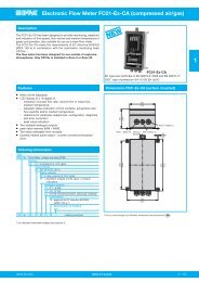
GMBHFlowMeter | FC100-CADescriptionThe analogue outputs and the signal outputs are galvanically isolatated from the other electronics.The two analogue output channels are not galvanically isolated from each other.There is no electrical isolation between power supply, controller system, sensor interface, monitoringhead and RS232 interface.The monitoring heads are connected by means of precut cables.Cables and user interface connections are shown in chapters 2.2.2 and circuit diagrams 2.2.2.1/2.2.2.2/2.2.2.3.System configuration and parameter settings can be modified by means of the keyboard if defaultvalues need to be changed (see chapter 5).This mainly applies to monitoring head selection, signal outputs (switch point setting) and analogueoutputs (zero point setting and scaling).1.2.1 <strong>User</strong> interfacesSignal outputs:(optional)Analogue outputs:1. R2 - Relay outputs (2 limit values)Two-channel galvanic isolationContact Form: Single pole double throw (SPDT)The channels may be assigned in menu “CONFIGURATION”, either individuallyor in pairs, to the physical quantities of temperature or flow. The switchon and off values can be set as desired in menu “PARAMETERS” (yet withinthe measuring range) for each contact.Please see chapter 7.4.1 for electrical connection.2. T4 – Transistor outputs (2 limit values + 2 status outputs or 2 limit values +1 status output + 1 pulse output)Four-channel galvanic isolation, transistor output (NPN) – collector/emitterfreely connectableChannel 1: common error signalChannel 2: busy signal or pulse outputChannels 3 and 4: Both channels may be assigned individually or in pairs tothe physical quantities of temperature or flow. The switch on or off values ofeach transistor output can be set as desired.Please see chapter 7.4.2 for electrical connection.Galvanic isolation, current or voltage outputPlease see the ordering number to find out whether it is a current or voltageoutput.Output quantities: 0/1 - 5 V FS (option V1)0/2 - 10 V FS (option V2)0/4 - 20 mA FS (option C1)These FS (full scale) output quantities apply to both channels as standard.20% zero elevation and FS value can be programmed. (see chapter 5.9)Shield connections are ungrounded.The shields of the signal cables should be applied on one side only.10