User ManUal - FlowVision GmbH
User ManUal - FlowVision GmbH
User ManUal - FlowVision GmbH

You also want an ePaper? Increase the reach of your titles
YUMPU automatically turns print PDFs into web optimized ePapers that Google loves.
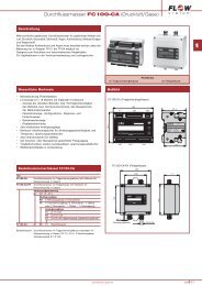
8FC100-CA | Flow MeterInstallationGMBH2.2.2.1 Circuit diagram FC100-CA (relay outputs)shield ground+U Vpower supply-U Vyellow R(HEIZ) -LOgreen R(HEIZ) -H Ibrown R(Tref) -HI1 2 3ANAO1white R(Tref) -LOcalorimetric monitoring headANA1GNDblue AGNDSGNDA1 ** LifYCY 4x 2x0,2 mm 2red ISSGNDA2 **ANAO2black SGNDANA2GNDgrey R(Tdiff)-LO1 2 3 4 5 6 7 8 9 101 2 3XV XSK XREMFC100-CAXSE XAO XAH1 2 3 41 2 3 4 5 6 7TXDRXDGNDSGNDNC*pink R(Tdiff)-HItotalizer resetFlow Controller81 2 3 4 5 6 7NC*SGNDL 1LIM1LIM1COM/LIM1SGNDL 2LIM2LIM2COM/LIM2RS232communicationinterface* NC: not connected** SGNDA1SGNDA2} ungroundedApply shield on one side only.analogue outputs **C1, V1, V2signal outputsfig. 1829