User ManUal - FlowVision GmbH
User ManUal - FlowVision GmbH
User ManUal - FlowVision GmbH

You also want an ePaper? Increase the reach of your titles
YUMPU automatically turns print PDFs into web optimized ePapers that Google loves.
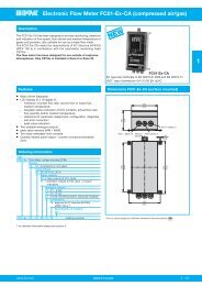
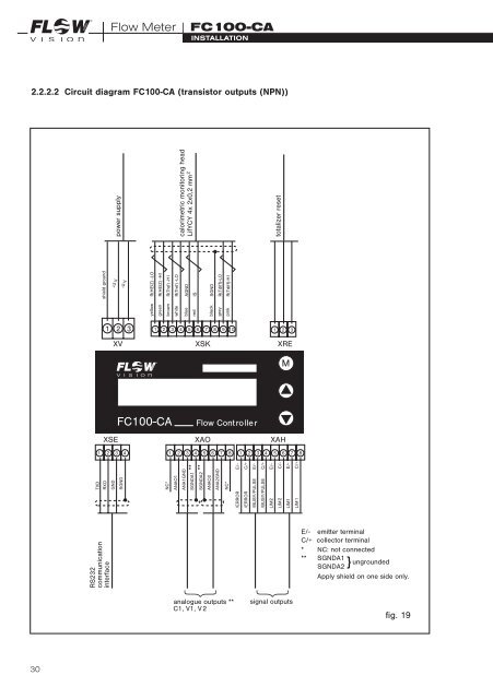
GMBHFlow Meter | FC100-CAInstallation2.2.2.2 Circuit diagram FC100-CA (transistor outputs (NPN))shield ground+U Vpower supply-U Vyellow R(HEIZ) -LOgreen R(HEIZ) -H Ibrown R(Tref) -HI1 2 3ANAO1white R(Tref) -LOANA1GNDcalorimetric monitoring headblue AGNDSGNDA1 ** LifYCY 4x 2x0,2 mm 2red ISSGNDA2 **ANAO2black SGNDANA2GNDgrey R(Tdiff)-LO1 2 3 4 5 6 7 8 9 101 2 3XV XSK XREMFC100-CAXSE XAO XAH1 2 3 41 2 3 4 5 6 7TXDRXDGNDSGNDNC*pink R(Tdiff)-HItotalizer resetFlow Controller81 2 3 4 5 6 7NC*/ERROR E/-/ERROR C/+/BUSY/PULSE E/-/BUSY/PULSE C/+LIM2 E/-LIM2 C/-LIM1 E/-LIM1 C/+8RS232communicationinterfaceE/- emitter terminalC/+ collector terminal* NC: not connected** SGNDA1SGNDA2} ungroundedApply shield on one side only.analogue outputs **C1, V1, V2signal outputsfig. 1930