User ManUal - FlowVision GmbH
User ManUal - FlowVision GmbH
User ManUal - FlowVision GmbH

You also want an ePaper? Increase the reach of your titles
YUMPU automatically turns print PDFs into web optimized ePapers that Google loves.
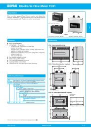
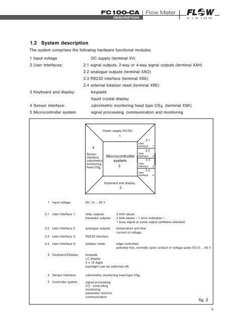
FC100-CA | Flow MeterDescriptionGMBH1.2 System descriptionThe system comprises the following hardware functional modules:1 Input voltage DC supply (terminal XV)2 <strong>User</strong> interfaces: 2.1 signal outputs, 2-way or 4-way signal outputs (terminal XAH)2.2 analogue outputs (terminal XAO)2.3 RS232 interface (terminal XSE)2.4 external totalizer reset (terminal XRE)3 Keyboard and display: keypadsliquid crystal display4 Sensor interface: calorimetric monitoring head type CSx_ (terminal XSK)5 Microcontroller system: signal processing, communication and monitoring4Sensorinterfacecalorimetricmonitoringhead CSxPower supply DC/DC1Microcontrollersystem52.1<strong>User</strong>interface 12.2<strong>User</strong>interface 22.3<strong>User</strong>interface 32.4<strong>User</strong>interface 4Keyboard and display31 Input voltage:DC 10 … 40 V2.1 <strong>User</strong> interface 1:2.2 <strong>User</strong> interface 2:relay outputs: 2 limit valuestransistor outputs: 2 limit values + 1 error indication +1 busy signal or pulse output (software selected)analogue outputs:2.3 <strong>User</strong> interface 3: RS232 interfacetemperature and flowcurrent or voltage2.4 <strong>User</strong> interface 4: totalizer reset: edge controlledpotential free, normally open contact or voltage pulse DC10 … 40 V3 Keyboard/Display:4 Sensor interface:5 Controller system :keypadsLC display2 x 16 digitsbacklight (can be switched off)calorimetric monitoring head type CSxsignal processingI/O - controllingmonitoringparameter memorycommunicationfig. 29