User ManUal - FlowVision GmbH
User ManUal - FlowVision GmbH
User ManUal - FlowVision GmbH

Create successful ePaper yourself
Turn your PDF publications into a flip-book with our unique Google optimized e-Paper software.
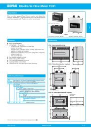
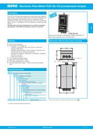
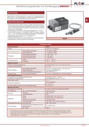
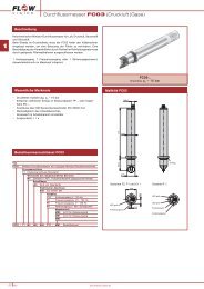
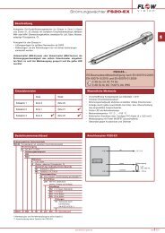
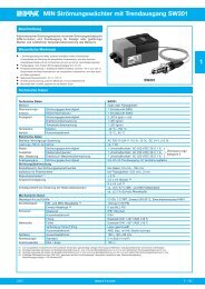
GMBHFlowMeter | FC100-CADescription1 DescriptionFlow Meter FC100-CA is suitable for compressed-air and other gas flow measurements undervarious pressure conditions. It operates on the calorimetric principle and is to be used together withmonitoring heads CSx-...These quantities are made available to the user as analogue electrical signals, physically isolated, ascurrent or voltage output and may be monitored by means of a limit monitor.As relay outputs or transistor outputs the digital signals enable the user to integrate the FC100-CAinto a control and monitoring system.The transistor outputs enable the user to additionally process fault, status and volume pulse indicationsin the control system.A RS232 interface enables communication with FC100-CA.1.1 Measuring procedure1.1.1 Calorimetric measuring procedureThe calorimetric measuring procedure is based on the physics of heat dissipation, i.e. a body with atemperature higher than its surroundings supplies a medium flowing past that body with energy in theform of heat. The amount energy supplied is a function of temperature difference ∆ϑ and mass flow.Flow Meter FC100-CA operates on the CTD (Constant-Temperature-Difference) method:The temperature difference ∆ϑ between the two sensors is kept constant and the mass flow is determinedby measuring the calorific power.Fig. 1 is a schematic diagram of a CTD method based sensor. Two temperature-sensitive resistors(sensor elements RS and RM) are immersed in the medium. Sensor RM assumes the temperature ofthe medium ϑ M whilst heater resistor RH heats element RS to temperature ϑ S. As a function of themedium, the temperature differential ∆ϑ = ϑ S - ϑ M is preselected as a reference variable by theCTD control and is kept constant. The required calorific power is a function of mass flow so that thecontrol variable y of the control can be used for evaluation.RMRSRHmmediumcontrol loopK pKpϑϑSMK p−+-x xdwI HK p,T nyU Im: mass floww: reference variable ( Δϑ)xd: system deviationy: control variableyx: actual value ( ϑS-ϑ M) I H : heater currentfig. 16