Altistart 22 - Schneider Electric
Altistart 22 - Schneider Electric
Altistart 22 - Schneider Electric
- No tags were found...

You also want an ePaper? Increase the reach of your titles
YUMPU automatically turns print PDFs into web optimized ePapers that Google loves.
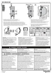
WiringRefer to application diagrams that display the logic controlling the isolation device via the detected fault relay.CAUTIONMOTOR OVERHEATING HAZARDIf the solid-state switches on the ATS<strong>22</strong> become inoperable, single-phase operation of the motor can result.• Use an isolation device consisting of either a circuit breaker equipped with a shunt trip coil or an electromagnetic contactor to openthe line-side of the soft starter.• The isolation device must be capable of interrupting the motor locked rotor current.• Connect the detected fault relay of the soft starter to open the isolation device in the event of a soft starter trip.Failure to follow these instructions can result in injury or equipment damage.WARNINGINADEQUATE SYSTEM GROUNDING- BRANCH CIRCUIT CONDUCTOR HAZARDIf system grounding is not adequate for ground fault levels, use properly coordinated external ground fault protection. Possible solutionsinclude:• Time delay fuses coordinated to 125% of motor FLA.• A properly coordinated external overload relay.Failure to follow these instructions can result in death, serious injury, or equipment damage.System GroundingIf system grounding is not adequate to handle ground trip levels which can exceed 1300% of motor full load amps (Motor FLA), then thisdevice may not protect the branch circuit conductors. In this case, external ground trip protection must be properly coordinated.Recommended solutions include:• Time delay fuses coordinated to 125% of motor FLA. The fuses listed in the chapter Branch circuit protection are sized to provideproper coordination and may be used for applications that do not require start times longer than 50 seconds at 300% current limit or20 seconds at 500% current limit.• External overload relay. For multi-motor applications, applications in which motor does not match the soft starter size, or applicationsthat use a full voltage bypass scheme, an external overload relay can be coordinated to protect conductors from a high-impedanceground trip.General wiring practicesWhen wiring ATS<strong>22</strong> soft starter, follow the wiring practices required by national and local electrical codes. In addition, follow theseguidelines:• Use metallic conduit for all soft starter wiring. Do not run control and power wiring in the same conduit.• Separate metallic conduits carrying power wiring or low-level control wiring by at least 80 mm (3 in).• Separate non-metallic conduits or cable trays used to carry power wiring from metallic conduit carrying low-level control wiring by atleast 305 mm (12 in).• Always cross power and control wiring at right angles.• Keep the control circuits away from the power cables.Adaptation to line inputThe control circuit is completely independent of the power circuit. To apply control voltage, follow the instructions on the label located onthe soft starter terminal strip. Connect single phase voltage of 110 or 230 Vac supply to terminals CL1 and CL2.The power circuit adapts automatically to the input line voltage and frequency over a range of 230 to 440 V for ATS<strong>22</strong>pppQ soft starters,and over a range of 208 to 600 V for ATS<strong>22</strong>pppS6 and ATS<strong>22</strong>pppS6U soft starters.28 BBV51330 08/2012