LATVIA UNIVERSITY OF AGRICULTURE - Latvijas ...
LATVIA UNIVERSITY OF AGRICULTURE - Latvijas ...
LATVIA UNIVERSITY OF AGRICULTURE - Latvijas ...
- No tags were found...

Create successful ePaper yourself
Turn your PDF publications into a flip-book with our unique Google optimized e-Paper software.
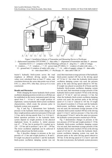
Janis Laceklis-Bertmanis, Vilnis Pirs,Eriks Kronbergs, Aivars Metla-Rozentāls, Māris MetlaPHYSICAL MODEL <strong>OF</strong> TRACTOR IMPLEMENTFigure 3. Installation Scheme of Transmitter and Measuring Device to PicoScope:1 – diplacement transmitter DTCH1000C; 2 – data cable; 3 – alignement of transmitter and data; 4 – pressuretransmtter ECO-1; 5 – computer with PicoTehnology software; 6 – plug box; 7 – cable of voltage;8 – windrow „ – ”; 9 – windrow „ + ”; 10 – power trade (PT 4862); 11 – windrow of outlet with value „ – ”;12 – ground bed; 13 windrow of outlet with value „ + ” ; 14 – cable of suppply voltage; 15 – data cable;16 – inlet chanel BNC; 17 –PicoScope; 18 – data cable USB 2.0.tractor’s hydraulic hitch-system across the roadroughness at different driving speeds. Averagevalues were calculated from at least 27 values, andcorrelation between the series data points was at least0.95, i.e., above 95%. After that, curves p=f (v) wereconstructed.Results and DiscussionWhile changing the tractor hydraulic hitch-systemoscillation damping position (switch on or off) that canbe established on the tractor instrument panel, drivingspeed from 3 – 14 km h -1 and weight position onimplement, various hydraulic hitch-system oscillationcharacteristics, which create the pressure pulse inhydraulic system were acquired.Fig. 4 and Fig. 5 demonstrate how hydraulicpressure in the hydraulic hitch-system changes at allthree weight positions and at tyre pressures 0.8 bar and1.2 bar, and at driving speeds from 3 to 13.8 km h -1 .Initial operation pressures in the hydraulic hitchsystemdepend on weight position on the physicalimplement boom. In position A, initial pressurewas 67 – 70 bar, but in position B it reached up to120 – 125 bar and in position C up to 145 – 150 bar.The lower oscillation amplitude can be achieved ifweight is placed near the hitch-system.Fig. 4 describes changes in pressure at the tyrepressure of 1.2 bar and weight position A, B and C.If weight was placed in position C and the hydraulichitch-system oscillation damping system was notused, then maximum average pressure of the hydraulichitch-system reached 220 bar at the driving speedof 7.8 km h -1 , but when the hydraulic hitch-systemoscillation damping system was used, the pressurepulse at the same driving speed reduced to 185 bar.If weight was placed on position B of boom and thehydraulic hitch-system oscillation damping systemwas not used, then maximum average pressure of thehydraulic hitch-system reached 170 bar at the drivingspeed of 7.8 km h -1 and tyre pressure 1.2 bar, butwhen the hydraulic hitch-system oscillation dampingsystem was used, the pressure pulse at the drivingspeed of 11.2 km h -1 reduced to 165 bar. If weightwas placed in position A of boom and the hydraulichitch-system oscillation damping system was orwas not used, the maximum average pressure of thehydraulic hitch-system reached 100 bar at the drivingspeed 11.2 km h -1 and tyre pressure 1.2 bar, but at thedriving speed 7.8 km h -1 and at the same tyre pressurethe hydraulic system pressures reached up to 88 bar.Fig. 5 demonstrates changes in pressure at thetyre pressure of 0.8 bar and weight position C. If thehydraulic hitch-system oscillation damping systemwas not used, then maximum average pressure of thehydraulic hitch-system reached 210 bar at the drivingspeed of 6.4 km h -1 , but when the hydraulic hitchsystemoscillation damping system was used, thepressure pulse at the same driving speed reduced to185 bar. At the driving speed of 11.2 km h -1 and withthe same tyre pressure, the hydraulic system pressuresResearch for Rural Development 2012219