

Flexicom cx combination boiler - installation and service manual
Flexicom cx combination boiler - installation and service manual
Flexicom cx combination boiler - installation and service manual

You also want an ePaper? Increase the reach of your titles
YUMPU automatically turns print PDFs into web optimized ePapers that Google loves.
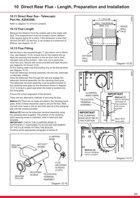
10 Direct Rear Flue - Length, Preparation <strong>and</strong> Installation10.11 Direct Rear flue - TelescopicPart No. A2043500.Refer to diagram 10.19 for kit contents.1480910.12 Flue LengthMeasure the distance from the outside wall to the inside wallface. This measurement must not exceed 512mm (465mmif the upward piping kit is used). If the dimension is less than291mm DO NOT cut the flue, it can project to a maximum of600mm, see diagram 10.15.10.13 Flue FittingSet the flue to the required length ‘Y’ plus 24mm min to 28mmmax, see diagram 10.20, ensure the air duct seams line up.Mark the securing hole position in the air duct. Drill a 3mmdiameter hole at this position, take care not to pierce theinner flue duct. Secure with screw provided <strong>and</strong> tape the joint,see diagrams 10.19 <strong>and</strong> 10.20.Fit the sealing collar onto the locating ring on the flue terminal,see diagram 10.19.Push the telescopic terminal assembly into the wall, externallyor internally, initially.Draw the telescopic flue through the wall <strong>and</strong> engage thetelescopic terminal assembly into the clamping b<strong>and</strong> grips.The telescopic terminal assembly must be pulled forward ofthe clamping b<strong>and</strong> grips by the dimension shown in diagram10.21 to ensure a good seal when the <strong>boiler</strong> is located ontothe fixing plate.Ensure the correct alignment of the terminal.There are two alternative methods of securing the flue:-Method (1) There are six holes provided in the clamping b<strong>and</strong>grips, three of these should be used to secure the flue. Mark<strong>and</strong> drill 3mm holes in the air duct then secure to the clampinggrip with the screws provided.Method (2) Secure the telescopic terminal assembly usingthe clamping b<strong>and</strong> supplied. The position of the clampingb<strong>and</strong> securing screw is important, refer to label <strong>and</strong> walltemplate.IMPORTANT: CHECK THE CLAMPING BAND ISSUFFICIENTLY TIGHTENED TO AVOID ANY MOVEMENTOF THE FLUE WHEN FITTING THE BOILER.Continue at the appropriate paragraph of section 8.Diagram 10.20Method (1)Secure clampingb<strong>and</strong> grips atthree positionswith screwsprovided1480815419Method (2)Secure clampingb<strong>and</strong> in positionDiagram 10.21Diagram 10.1929


