

Flexicom cx combination boiler - installation and service manual
Flexicom cx combination boiler - installation and service manual
Flexicom cx combination boiler - installation and service manual

Create successful ePaper yourself
Turn your PDF publications into a flip-book with our unique Google optimized e-Paper software.
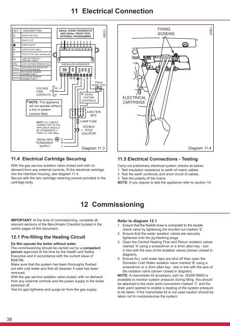
11 Electrical Connection139221336911.4 Electrical Cartridge SecuringDiagram 11.3With the gas <strong>service</strong> isolation valve closed <strong>and</strong> with nodem<strong>and</strong> from any external controls, fit the electrical cartridgeinto the interface housing, see diagram 11.4.Secure with the two cartridge retaining screws provided in thecartridge body.11.5 Electrical Connections - TestingDiagram 11.4Carry out preliminary electrical system checks as below:1. Test insulation resistance to earth of mains cables.2. Test the earth continuity <strong>and</strong> short circuit of cables.3. Test the polarity of the mains.NOTE: If you require to test the appliance refer to section 14.12 CommissioningIMPORTANT: At the time of commissioning, complete allrelevant sections of the Benchmark Checklist located in thecentre pages of this document.12.1 Pre-filling the Heating CircuitDo Not operate the <strong>boiler</strong> without water.The commissioning should be carried out by a competentperson approved at the time by the Health <strong>and</strong> SafetyExecutive <strong>and</strong> in accordance with the current issue ofBS6798.Make sure that the system has been thoroughly flushedout with cold water <strong>and</strong> that all cleanser if used has beenremoved.With the gas <strong>service</strong> isolation valve closed, with no dem<strong>and</strong>from any external controls <strong>and</strong> the power supply to the <strong>boiler</strong>switched off.Test for gas tightness <strong>and</strong> purge air from the gas supply.Refer to diagram 12.11. Ensure that the flexible hose is connected to the doublecheck valve by tightening the knurled nut marked ‘E’.2. Ensure that the water isolation valves are securelytightened onto the jig blanking plugs.3. Open the Central Heating Flow <strong>and</strong> Return isolation valvesmarked ‘A’ using a screwdriver or a 4mm allen key - slotin line with the axis of the isolation valves (shown closed indiagram).4. Ensure ALL cold water taps are shut off then open theDomestic Cold Water isolation valve marked ‘B’ using ascrewdriver or a 3mm allen key - slot in line with the axis ofthe isolation valve (shown closed in diagram).NOTE: A manometer kit accessory, part no. 0020016995 isavailable to monitor system pressure during filling, this shouldbe attached to the drain point connection marked ‘C’ <strong>and</strong> thedrain point opened to enable a reading of the system pressureto be taken. If the manometer kit is not used caution should betaken not to overpressurise the system.38


