

Flexicom cx combination boiler - installation and service manual
Flexicom cx combination boiler - installation and service manual
Flexicom cx combination boiler - installation and service manual

You also want an ePaper? Increase the reach of your titles
YUMPU automatically turns print PDFs into web optimized ePapers that Google loves.
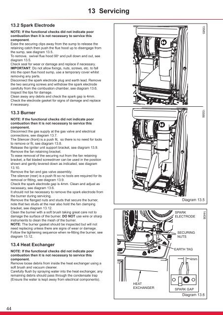
13 Servicing13.2 Spark ElectrodeNOTE: If the functional checks did not indicate poorcombustion then it is not necessary to <strong>service</strong> thiscomponent.Ease the securing clips away from the sump to release theretaining catch then push the flue hood up to disengage fromthe sump, see diagram 13.5.To remove, swivel flue hood 90 o <strong>and</strong> pull down <strong>and</strong> out, seediagram 13.5.Check seal for wear or damage <strong>and</strong> replace if necessary.IMPORTANT: Do not allow fixings, nuts, screws, etc. to fallinto the open flue hood sump, use a temporary cover whilstremoving any parts.Disconnect the spark electrode plug <strong>and</strong> earth lead. Removethe two securing screws <strong>and</strong> withdraw the spark electrodecarefully from the combustion chamber, see diagram 13.6.Inspect the tips for damage.Clean away any debris <strong>and</strong> check the spark gap is 4mm.Check the electrode gasket for signs of damage <strong>and</strong> replaceif necessary.13.3 BurnerNOTE: If the functional checks did not indicate poorcombustion then it is not necessary to <strong>service</strong> thiscomponent.Disconnect the gas supply at the gas valve <strong>and</strong> electricalconnections, see diagram 13.7.The Silencer (front) is a push fit, so there is no need for toolsto remove or fit, see diagram 13.8.Release the igniter unit support bracket, see diagram 13.9.Remove the fan retaining bracket.To ease removal of the securing nut from the fan retainingbracket, a flat bladed screwdriver can be used in the positionshown <strong>and</strong> gently levered down as indicated, see diagram13.10.Remove the fan <strong>and</strong> gas valve assembly.The silencer (rear) is a push fit so no tools are required for itsremoval or fitting, see diagram 13.9.Check the spark electrode gap is 4mm. Clean <strong>and</strong> adjust asnecessary, see diagram 13.6.It should not be necessary to remove the spark electrode fromthe burner during servicing.Remove the flanged nuts <strong>and</strong> studs that secure the burner,note that two studs at the rear also hold the fan clampingbracket, see diagram 13.12.Clean the burner with a soft brush taking great care not todamage the surface of the burner. DO NOT use wire or sharpinstruments to clean the mesh of the burner.NOTE: The burner gasket should be inspected but will notneed replacing unless there are signs of wear or damage.Follow the tightening sequence when re-fitting the burner, seediagram 13.12.1558515586Diagram 13.51440813.4 Heat ExchangerNOTE: If the functional checks did not indicate poorcombustion then it is not necessary to <strong>service</strong> thiscomponent.Remove loose debris from inside the heat exchanger using asoft brush <strong>and</strong> vacuum cleaner.Carefully flush by spraying water into the heat exchanger, anyremaining debris should pass through the condensate trap(Ensure the water is kept away from electrical components).Diagram 13.644


