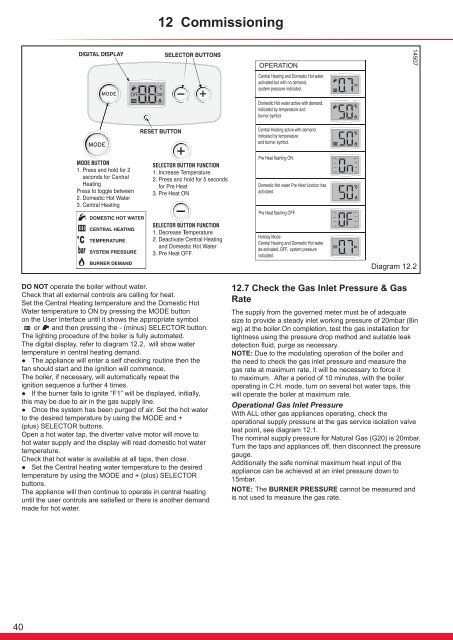
12 Commissioning14507MODEMODEDiagram 12.2DO NOT operate the <strong>boiler</strong> without water.Check that all external controls are calling for heat.Set the Central Heating temperature <strong>and</strong> the Domestic HotWater temperature to ON by pressing the MODE buttonon the User Interface until it shows the appropriate symbolor <strong>and</strong> then pressing the - (minus) SELECTOR button.The °C lighting procedure of the <strong>boiler</strong> is fully automated.The bar digital°Cdisplay, refer to diagram 12.2, will show waterbartemperature in central heating dem<strong>and</strong>.● The appliance will enter a self checking routine then thefan should start <strong>and</strong> the ignition will commence.The <strong>boiler</strong>, if necessary, will automatically repeat theignition sequence a further 4 times.● If the burner fails to ignite “F1” will be displayed, initially,this may be due to air in the gas supply line.● Once the system has been purged of air. Set the hot waterto the desired temperature by using the MODE <strong>and</strong> +(plus) SELECTOR buttons.Open a hot water tap, the diverter valve motor will move tohot water supply <strong>and</strong> the display will read domestic hot watertemperature.Check that hot water is available at all taps, then close.● Set the Central heating water temperature to the desiredtemperature by using the MODE <strong>and</strong> + (plus) SELECTORbuttons.The appliance will then continue to operate in central heatinguntil the user controls are satisfied or there is another dem<strong>and</strong>made for hot water.12.7 Check the Gas Inlet Pressure & GasRateThe supply from the governed meter must be of adequatesize to provide a steady inlet working pressure of 20mbar (8inwg) at the <strong>boiler</strong>.On completion, test the gas <strong>installation</strong> fortightness using the pressure drop method <strong>and</strong> suitable leakdetection fluid, purge as necessary.NOTE: Due to the modulating operation of the <strong>boiler</strong> <strong>and</strong>the need to check the gas inlet pressure <strong>and</strong> measure thegas rate at maximum rate, it will be necessary to force itto maximum. After a period of 10 minutes, with the <strong>boiler</strong>operating in C.H. mode, turn on several hot water taps, thiswill operate the <strong>boiler</strong> at maximum rate.Operational Gas Inlet PressureWith ALL other gas appliances operating, check theoperational supply pressure at the gas <strong>service</strong> isolation valvetest point, see diagram 12.1.The nominal supply pressure for Natural Gas (G20) is 20mbar.Turn the taps <strong>and</strong> appliances off, then disconnect the pressuregauge.Additionally the safe nominal maximum heat input of theappliance can be achieved at an inlet pressure down to15mbar.NOTE: The BURNER PRESSURE cannot be measured <strong>and</strong>is not used to measure the gas rate.40
12 CommissioningGas RateMake sure that ALL other gas burning appliances <strong>and</strong> pilotlights are off.Check the gas rate using the gas meter test dial <strong>and</strong> stopwatch, at least 10 minutes after the burner has lit.The approximate maximum gas rates are:kW m3/hr ft3/hr kW m3/hr ft3/hr20 2.1 74.230 3.2 113 19 2.0 70.629 3.1 109.5 18 1.9 67.128 3.0 106 17 1.8 63.627 2.9 102.4 16 1.7 60.026 2.8 98.9 15 1.6 56.525 2.6 91.8 14 1.5 53.024 2.5 88.3 13 1.4 49.523 2.4 84.8 12 1.3 45.922 2.3 81.2 11 1.2 42.421 2.2 77.7 10 1.1 38.912.8 Central Heating Range RatingThe <strong>boiler</strong>s are fully modulating for central heating, thereforeit is not necessary to range rate them, however, if desired, youcan adjust the CH output in 1kW increments between:24<strong>cx</strong> : 10 - 18kW30<strong>cx</strong> : 10 - 24kW35<strong>cx</strong> : 10 - 30kWas follows:a) Press <strong>and</strong> hold the ‘MODE’ <strong>and</strong> “+” button for 5seconds. The display will change to flashing ‘0’.b) Use the ‘+’ or ‘-’ button to scroll to 96.c) Press ‘MODE’ <strong>and</strong> hold 5 seconds to confirm.d) The display now shows a flashing ‘d. 0’.e) The part load setting is displayed in kW.Press ‘MODE’ the max rate will be indicated, tochange the value to the desired setting, use the ‘+’or ‘-’ button.f) Press ‘MODE’ for 5 sec to confirm the new settinghas been saved.g) Press <strong>and</strong> hold ‘MODE’ <strong>and</strong> “+” to exit.Please refer to the above table to check the gas rates.12.9 Heating System24<strong>cx</strong> : 1.9m3/h (68ft/3/h)30<strong>cx</strong> : 2.6m3/h (92ft/3/h)35<strong>cx</strong> : 3.3m3/h (115ft/3/h)Ensure that the external controls <strong>and</strong> programmer are callingfor heat.Fully open all radiator valves, flow control valve, if fitted, seediagram 5.1.Press the “MODE” button to change to the CH.Balance the radiators as required <strong>and</strong> if fitted adjust valve togive the required system differential. Turn off all radiators thatcan be shut off by the user <strong>and</strong> check to see if less than themaximum differential allowed of 20 o C can be achieved acrossflow <strong>and</strong> return.NOTE: Should the system require that the appliance hasto be adjusted, the front casing will need to be removed asdescribed in the servicing section 13 <strong>and</strong> the control boxlowered into its <strong>service</strong> position.The appliance pump has two speeds <strong>and</strong> can be adjusted tosuit the requirements of the system.The appliance has an inbuilt automatic adjustable bypassvalve. The pressure can be adjusted between approx 1.5<strong>and</strong> 3.5mH2O but is factory pre-set to approx 2.5mH2O. Thepressure changes by approx 0.1mH2O for each full turn of thebypass screw, see diagram 5.2. Turning clockwise increasesthe pressure <strong>and</strong> turning anti-clockwise decreases thepressure.Allow the system to reach maximum temperature then switchoff the <strong>boiler</strong> by isolating from the electrical supply.Drain the entire system rapidly whilst hot, using the drain tapsat all the low points of the system. Fill <strong>and</strong> vent the system asdescribed previously in section 12.2.Lock or remove the h<strong>and</strong>le from control valve, if fitted.Adjust the <strong>boiler</strong> temperature controls <strong>and</strong> any systemcontrols to their required settings.12.10 CompletionEnsure that the magnetic lighting instruction label is placed onthe surface of the <strong>boiler</strong> casing.GB: In addition it is necessary to complete the “Benchmark”logbook.IE: it is necessary to complete a “Declaration of Conformity” toindicate compliance to I.S.813. An example of this is given inthe current edition of I.S.813.12.11 Instruct the User● Demonstrate, then instruct the User about the lightingprocedure <strong>and</strong> heating system controls operation.● Advise that to ensure the continued efficient <strong>and</strong> safeoperation of the <strong>boiler</strong> it is recommended that it is checked<strong>and</strong> <strong>service</strong>d at regular intervals. The frequency of servicingwill depend upon the <strong>installation</strong> conditions <strong>and</strong> usage, but ingeneral, once a year should be enough.● Draw attention, if applicable, to the current issue of the GasSafety (Installation <strong>and</strong> Use) Regulations, Section 35, whichimposes a duty of care on all persons who let out any propertycontaining a gas appliance in the UK.● The user shall not interfere with or adjust sealedcomponents.● It is the Law that any servicing is carried out by acompetent person approved at the time by the Health <strong>and</strong>Safety Executive.● Advise the user that, like all condensing <strong>boiler</strong>s thisappliance will produce a plume of condensation from the flueterminal in cool weather. This is due to the high efficiency <strong>and</strong>hence low flue gas temperature of the <strong>boiler</strong>.● Advise the user of the precautions necessary to preventdamage to the system, <strong>boiler</strong> <strong>and</strong> the building, in the event ofthe heating system being out of use during frost or freezingconditions.● Advise the user that the permanent mains electrical supplySHOULD NOT be switched off, as the built in frost protection<strong>and</strong> pump saver program will not operate.● Advise the User if the mains electricity <strong>and</strong> gas are to beturned off for any long periods during severe weather, it isrecommended that the whole system, including the <strong>boiler</strong>,should be drained to avoid the risk of freezing.NOTE: Sealed System: Contact your <strong>installation</strong>/servicingcompany as draining, refilling <strong>and</strong> pressurising MUST becarried out by a competent person approved at the time bythe Health <strong>and</strong> Safety Executive.● Leave these instructions <strong>and</strong> the ‘Benchmark’ Installation,Commissioning <strong>and</strong> Service Record with the user.41