

Flexicom cx combination boiler - installation and service manual
Flexicom cx combination boiler - installation and service manual
Flexicom cx combination boiler - installation and service manual

You also want an ePaper? Increase the reach of your titles
YUMPU automatically turns print PDFs into web optimized ePapers that Google loves.
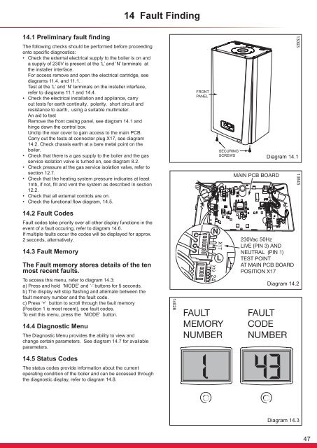
14 Fault Finding14.1 Preliminary fault findingThe following checks should be performed before proceedingonto specific diagnostics:• Check the external electrical supply to the <strong>boiler</strong> is on <strong>and</strong>a supply of 230V is present at the ‘L’ <strong>and</strong> ‘N’ terminals atthe installer interface.For access remove <strong>and</strong> open the electrical cartridge, seediagrams 11.4. <strong>and</strong> 11.1.Test at the ‘L’ <strong>and</strong> ‘N’ terminals on the installer interface,refer to diagrams 11.1 <strong>and</strong> 14.4.• Check the electrical <strong>installation</strong> <strong>and</strong> appliance, carryout tests for earth continuity, polarity, short circuit <strong>and</strong>resistance to earth, using a suitable multimeter.An aid to testRemove the front casing panel, see diagram 14.1 <strong>and</strong>hinge down the control box.Unclip the rear cover to gain access to the main PCB.Carry out the tests at connector plug X17, see diagram14.2. Check chassis earth at a bare metal point on the<strong>boiler</strong>.• Check that there is a gas supply to the <strong>boiler</strong> <strong>and</strong> the gas<strong>service</strong> isolation valve is turned on, see diagram 8.2.• Check pressure at the gas <strong>service</strong> isolation valve, refer tosection 12.7.• Check that the heating system pressure indicates at least1mb, if not, fill <strong>and</strong> vent the system as described in section12.2.• Check that all external controls are on.• Check the functional flow diagram, 14.5.13093Diagram 14.11384514.2 Fault CodesFault codes take priority over all other display functions in theevent of a fault occuring, refer to diagram 14.6.If multiple faults occur the codes will be displayed for approx.2 seconds, alternatively.14.3 Fault MemoryThe Fault memory stores details of the tenmost recent faults.To access this menu, refer to diagram 14.3:a) Press <strong>and</strong> hold ‘MODE’ <strong>and</strong> ‘-’ buttons for 5 seconds.b) The display will stop flashing <strong>and</strong> alternate between thefault memory number <strong>and</strong> the fault code.c) Press ‘+’ button to scroll through the fault memory(Position 1 is most recent), see fault codes.To exit this menu, press the ‘MODE’ button.14.4 Diagnostic MenuThe Diagnostic Menu provides the ability to view <strong>and</strong>change certain parameters. See diagram 14.7 for availableparameters.14.5 Status CodesThe status codes provide information about the currentoperating condition of the <strong>boiler</strong> <strong>and</strong> can be accessed throughthe diagnostic display, refer to diagram 14.8.14028Diagram 14.2Diagram 14.347


