

Flexicom cx combination boiler - installation and service manual
Flexicom cx combination boiler - installation and service manual
Flexicom cx combination boiler - installation and service manual

You also want an ePaper? Increase the reach of your titles
YUMPU automatically turns print PDFs into web optimized ePapers that Google loves.
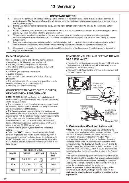
13 ServicingIMPORTANT NOTES:1. To ensure the continued efficient <strong>and</strong> safe operation of the <strong>boiler</strong> it is recommended that it is checked <strong>and</strong> <strong>service</strong>d atregular intervals. The frequency of servicing will depend upon the particular <strong>installation</strong> <strong>and</strong> usage, but in general once ayear should be enough.2. It is the Law that any servicing is carried out by a competent person approved at the time by the Health <strong>and</strong> SafetyExecutive.3. Before commencing with a <strong>service</strong> or replacement of parts the <strong>boiler</strong> should be isolated from the electrical supply <strong>and</strong> thegas supply should be turned off at the gas isolation valve.4. When replacing a part on this appliance, use only spare parts that you can be assured conform to the safety <strong>and</strong>performance specification that we require. Do not use reconditioned or copy parts that have not been clearly authorisedby Glow-worm.5. If any electrical connections have been disconnected <strong>and</strong> after their connection, checks to the earth continuity, polarity,short circuit <strong>and</strong> resistance to earth must be repeated using a suitable multimeter, as described in section 14.6. After servicing, complete the relevant Service Interval Record section of the Benchmark Checklist located in the centrepages of this document.General InspectionPrior to, during servicing <strong>and</strong> after any maintenance orchanged parts, the following must be checked.● The integrity of the flue system <strong>and</strong> flue seals.● The integrity of the appliance combustion circuit <strong>and</strong>relevant seals.● Electrical, gas <strong>and</strong> water connections.● System pressure.● the combustion performance, refer to the followingprocedure.● The operational gas inlet pressure <strong>and</strong> gas rates, refer tothe commissioning section paragraph 12.7.Correct any fault before continuing.COMPETENCY TO CARRY OUT THE CHECKOF COMBUSTION PERFORMANCENOTE: BS 6798: 2009 Specification for <strong>installation</strong> <strong>and</strong>maintenance of gas-fired <strong>boiler</strong>s of rated input not exceeding70kW net advises that:● The person carrying out a combustion measurement mustbe assessed as competent in the use of a flue gas analyser<strong>and</strong> the interpretation of the results.● The flue gas analyser used should be one meeting therequirements of BS7927 or BS-EN50379-3 <strong>and</strong> be calibratedin accordance with the analyser manufacturers’ requirements.● Competence can be demonstrated by satisfactorycompletion of the CPA1 ACS assessment, which coversthe use of electronic portable combustion gas analysers inaccordance with BS 7967, parts 1 to 4.● Ensure that the gas analyser is set to the correct fuelsetting.● Select the “ ”, constant central heating with DHWfunction by pressing °C the “Mode” button repeatedly, refer tobar °Ccommissioning section.Thebar<strong>boiler</strong> should fire automatically.NOTE: Safe combustion can only be verified by measuringCO/CO2 ratio. This must not exceed the value shown in thetable below.G20 BURNER % CO2MODEL CHECK SETTING CO/CO2ratio24<strong>cx</strong> 8.8 to 9.8 9.2 +0.3 0.004- 0.330<strong>cx</strong> 8.8 to 9.8 9.1 +0.3 0.004- 0.335<strong>cx</strong> 8.8 to 9.8 8.8 +0.3- 0.30.004COMBUSTION CHECK AND SETTING THE AIR/GAS RATIO VALVE● Remove the front casing panel, see diagram 13.2 <strong>and</strong> hingedown the control box. Taking care not to touch any internalcomponents, proceed as follows:● Connect the CO2 combustion analyser to the relevant testpoint, see diagram 13.1.1. Maximum Rate Check <strong>and</strong> AdjustmentDiagram 13.1NOTE: To verify the maximum gas rate CO2 setting theappliance must be checked at the maximum rate first. Pressthe “reset” button on the controls fascia, release <strong>and</strong>immediately press <strong>and</strong> hold in the “+” button. Afterapproximately 5 seconds “Hi” will be displayed. Pressingthe mode button when “Hi” is selected will force the <strong>boiler</strong>to maximum rate, the display will flash between “Hi” <strong>and</strong> the“default display” this will indicate the <strong>boiler</strong> has been forced tomaximum. Wait until the CO2 value is stable <strong>and</strong> check thatthe value is within the range specified in table in the “check”column.If the combustion reading is not within the acceptable valuesAND the integrity of the complete flue system <strong>and</strong> combustioncircuit seals have been verified <strong>and</strong> the inlet gas pressure(<strong>and</strong> gas rate) have been verified, then, it will necessary toadjust the combustion rate of the appliance.NOTE: Adjustment is made by turning the gas valvethrottle an ⅛ of a turn, waiting 1 minute to allow theappliance to stabilise before checking or making furtheradjustments.1544542


