

Flexicom cx combination boiler - installation and service manual
Flexicom cx combination boiler - installation and service manual
Flexicom cx combination boiler - installation and service manual

You also want an ePaper? Increase the reach of your titles
YUMPU automatically turns print PDFs into web optimized ePapers that Google loves.
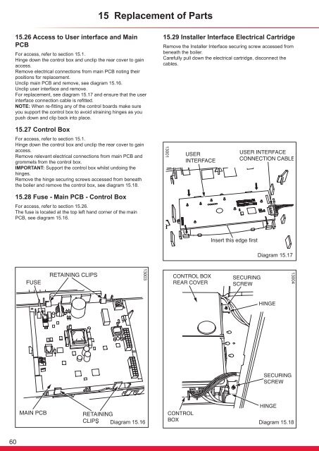
15 Replacement of Parts15.26 Access to User interface <strong>and</strong> MainPCBFor access, refer to section 15.1.Hinge down the control box <strong>and</strong> unclip the rear cover to gainaccess.Remove electrical connections from main PCB noting theirpositions for replacement.Unclip main PCB <strong>and</strong> remove, see diagram 15.16.Unclip user interface <strong>and</strong> remove.For replacement, see diagram 15.17 <strong>and</strong> ensure that the userinterface connection cable is refitted.NOTE: When re-fitting any of the control boards make sureyou support the control box to avoid straining hinges as youpush down <strong>and</strong> clip back into place.15.29 Installer Interface Electrical CartridgeRemove the Installer Interface securing screw accessed frombeneath the <strong>boiler</strong>.Carefully pull down the electrical cartridge, disconnect thecables.15.27 Control BoxFor access, refer to section 15.1.Hinge down the control box <strong>and</strong> unclip the rear cover to gainaccess.Remove relevant electrical connections from main PCB <strong>and</strong>grommets from the control box.IMPORTANT: Support the control box whilst undoing thehinges.Remove the hinge securing screws accessed from beneaththe <strong>boiler</strong> <strong>and</strong> remove the control box, see diagram 15.18.1300115.28 Fuse - Main PCB - Control BoxFor access, refer to section 15.26.The fuse is located at the top left h<strong>and</strong> corner of the mainPCB, see diagram 15.16.Diagram 15.171300413003Diagram 15.16Diagram 15.1860


