

Flexicom cx combination boiler - installation and service manual
Flexicom cx combination boiler - installation and service manual
Flexicom cx combination boiler - installation and service manual

You also want an ePaper? Increase the reach of your titles
YUMPU automatically turns print PDFs into web optimized ePapers that Google loves.
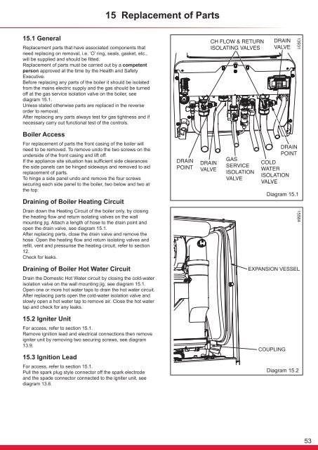
15 Replacement of Parts15.1 GeneralReplacement parts that have associated components thatneed replacing on removal, i.e. ‘O’ ring, seals, gasket, etc.,will be supplied <strong>and</strong> should be fitted.Replacement of parts must be carried out by a competentperson approved at the time by the Health <strong>and</strong> SafetyExecutive.Before replacing any parts of the <strong>boiler</strong> it should be isolatedfrom the mains electric supply <strong>and</strong> the gas should be turnedoff at the gas <strong>service</strong> isolation valve on the <strong>boiler</strong>, seediagram 15.1.Unless stated otherwise parts are replaced in the reverseorder to removal.After replacing any parts always test for gas tightness <strong>and</strong> ifnecessary carry out functional test of the controls.13931Boiler AccessFor replacement of parts the front casing of the <strong>boiler</strong> willneed to be removed. To remove undo the two screws on theunderside of the front casing <strong>and</strong> lift off.If the appliance site situation has sufficient side clearancesthe side panels can be hinged sideways <strong>and</strong> removed to aidreplacement of parts.To hinge a side panel undo <strong>and</strong> remove the four screwssecuring each side panel to the <strong>boiler</strong>, two below <strong>and</strong> two atthe top.Draining of Boiler Heating CircuitDrain down the Heating Circuit of the <strong>boiler</strong> only, by closingthe heating flow <strong>and</strong> return isolating valves on the wallmounting jig. Attach a length of hose to the drain point <strong>and</strong>open the drain valve, see diagram 15.1.After replacing parts, close the drain valve <strong>and</strong> remove thehose. Open the heating flow <strong>and</strong> return isolating valves <strong>and</strong>refill, vent <strong>and</strong> pressurise the heating circuit, refer to section12.Check for leaks.Diagram 15.115584Draining of Boiler Hot Water CircuitDrain the Domestic Hot Water circuit by closing the cold-waterisolation valve on the wall mounting jig, see diagram 15.1.Open one or more hot water taps to drain the hot water circuit.After replacing parts open the cold-water isolation valve <strong>and</strong>slowly open a hot water tap to remove air. Close the hot watertap <strong>and</strong> check for any leaks.15.2 Igniter UnitFor access, refer to section 15.1.Remove ignition lead <strong>and</strong> electrical connections then removeigniter unit by removing two securing screws, see diagram13.9.15.3 Ignition LeadFor access, refer to section 15.1.Pull the spark plug style connector off the spark electrode<strong>and</strong> the spade connector connected to the igniter unit, seediagram 13.6.Diagram 15.253


