

Flexicom cx combination boiler - installation and service manual
Flexicom cx combination boiler - installation and service manual
Flexicom cx combination boiler - installation and service manual

You also want an ePaper? Increase the reach of your titles
YUMPU automatically turns print PDFs into web optimized ePapers that Google loves.
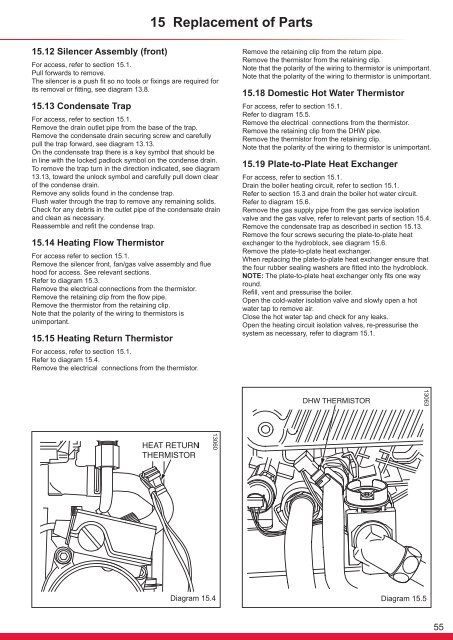
15 Replacement of Parts15.12 Silencer Assembly (front)For access, refer to section 15.1.Pull forwards to remove.The silencer is a push fit so no tools or fixings are required forits removal or fitting, see diagram 13.8.15.13 Condensate TrapFor access, refer to section 15.1.Remove the drain outlet pipe from the base of the trap.Remove the condensate drain securing screw <strong>and</strong> carefullypull the trap forward, see diagram 13.13.On the condensate trap there is a key symbol that should bein line with the locked padlock symbol on the condense drain.To remove the trap turn in the direction indicated, see diagram13.13, toward the unlock symbol <strong>and</strong> carefully pull down clearof the condense drain.Remove any solids found in the condense trap.Flush water through the trap to remove any remaining solids.Check for any debris in the outlet pipe of the condensate drain<strong>and</strong> clean as necessary.Reassemble <strong>and</strong> refit the condense trap.15.14 Heating Flow ThermistorFor access refer to section 15.1.Remove the silencer front, fan/gas valve assembly <strong>and</strong> fluehood for access. See relevant sections.Refer to diagram 15.3.Remove the electrical connections from the thermistor.Remove the retaining clip from the flow pipe.Remove the thermistor from the retaining clip.Note that the polarity of the wiring to thermistors isunimportant.15.15 Heating Return ThermistorFor access, refer to section 15.1.Refer to diagram 15.4.Remove the electrical connections from the thermistor.Remove the retaining clip from the return pipe.Remove the thermistor from the retaining clip.Note that the polarity of the wiring to thermistor is unimportant.Note that the polarity of the wiring to thermistor is unimportant.15.18 Domestic Hot Water ThermistorFor access, refer to section 15.1.Refer to diagram 15.5.Remove the electrical connections from the thermistor.Remove the retaining clip from the DHW pipe.Remove the thermistor from the retaining clip.Note that the polarity of the wiring to thermistor is unimportant.15.19 Plate-to-Plate Heat ExchangerFor access, refer to section 15.1.Drain the <strong>boiler</strong> heating circuit, refer to section 15.1.Refer to section 15.3 <strong>and</strong> drain the <strong>boiler</strong> hot water circuit.Refer to diagram 15.6.Remove the gas supply pipe from the gas <strong>service</strong> isolationvalve <strong>and</strong> the gas valve, refer to relevant parts of section 15.4.Remove the condensate trap as described in section 15.13.Remove the four screws securing the plate-to-plate heatexchanger to the hydroblock, see diagram 15.6.Remove the plate-to-plate heat exchanger.When replacing the plate-to-plate heat exchanger ensure thatthe four rubber sealing washers are fitted into the hydroblock.NOTE: The plate-to-plate heat exchanger only fits one wayround.Refill, vent <strong>and</strong> pressurise the <strong>boiler</strong>.Open the cold-water isolation valve <strong>and</strong> slowly open a hotwater tap to remove air.Close the hot water tap <strong>and</strong> check for any leaks.Open the heating circuit isolation valves, re-pressurise thesystem as necessary, refer to diagram 15.1.1306313060Diagram 15.4Diagram 15.555


