

Flexicom cx combination boiler - installation and service manual
Flexicom cx combination boiler - installation and service manual
Flexicom cx combination boiler - installation and service manual

You also want an ePaper? Increase the reach of your titles
YUMPU automatically turns print PDFs into web optimized ePapers that Google loves.
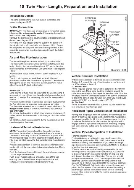
10 Twin Flue - Length, Preparation <strong>and</strong> InstallationInstallation DetailsThe parts available for a twin flue system <strong>installation</strong> areshown in diagram 10.30.12985Boiler ConnectionIMPORTANT: The flue seals are sensitive to mineral oil basedlubricants. Do not grease the seals. If the seals do need tobe lubricated use only water.Remove the top flue outlet cover complete with resonator <strong>and</strong>discard, see diagram 10.4.Place the twin flue adaptor onto the outlet of the <strong>boiler</strong> withthe air inlet to the left h<strong>and</strong> side, see diagram 10.31. Securethe adaptor to the top panel with the screws provided. Careshould be taken when inserting the screw through the hole inadaptor top.Air <strong>and</strong> Flue Pipe InstallationThe air <strong>and</strong> flue pipes can now be built up from the <strong>boiler</strong>.The flue must be designed with a continuous fall towards the<strong>boiler</strong>. If using the horizontal flue pipe or 90° bends the pipemust be inclined at 44mm/metre (2.5°) minimum, see diagram10.29.Alternatively if space allows, use 45° bends in place of 90ºbends.To aviod rain ingress to the air Inlet terminal, it is goodpractice to aim the inlet downwards by approx 2° as rain c<strong>and</strong>amage the <strong>boiler</strong>. The Flue outlet pipe must always run at44mm/metre (2.5°) back to the <strong>boiler</strong>.IMPORTANT:-Long lengths of flues must be secured to the wall or ceiling itruns against. Use at least one fixing bracket on each flue jointused or on straight flue runs every joint <strong>and</strong> for every metreflue run.Provision must be made in concealed boxing or ductwork thatthe flue joints can be inspected during annual servicing.The flue seals are sensitive to mineral oil based lubricants. Donot grease the seals. If the seals do need to be lubricateduse only water.Do not use the flue pipe to attach other pipes or equipment. Ifvisible, advise the householder not to hang or clip items to fluepipes.Do not stress the flue connections during the <strong>installation</strong>, thiscan damage the flue seals.Horizontal Terminal InstallationNOTE: The air inlet terminal <strong>and</strong> the flue outlet terminalsmust never be installed on the opposite sides of a property.Termination must only be on the same wall or adjacent walls.When installed close together separated vertically, the airinlet must be fitted below the flue outlet terminal (see diagram10.29).With due consideration to terminal clearances mentioned insection 4.2 drill the one or two holes as required with a 90mmcore drill.Push the horizontal terminal through the wall allowing approx.100mm to protrude outside.Push a grey rubber wall seal onto either side of the wallensuring that both wall seals are pushed up to the wallsurface, see examples (b) <strong>and</strong> (c) diagram 10.29.Vertical Terminal InstallationDiagram 10.31With due consideration to terminal clearances mentioned inSection 4.2, project the rise of the flue pipe to roof level <strong>and</strong>cut 150mm hole in the roof.(a) Pitched RoofFit the required pitched roof weather collar over the 150mmhole in the roof. Make good the tiling or slating around thecollar incorporating the flashing of the weather collar. Positionthe angle cap over the weather collar in the correct orientationto attain the correct angle for your roof. One way round givesa pitch of 25°-38° <strong>and</strong> the other gives 37°- 50°.(b) Flat RoofFit the aluminium weather collar over the 150mm hole in theroof ensuring a weather tight seal.Horizontal Pipes-Completion of InstallationHaving built the pipe(s) from the <strong>boiler</strong> to the terminal(s), thelength of the final pipe piece can be determined. Cut pipes atthe opposite end to the ‘O’ ring seal making square <strong>and</strong> freefrom burrs. Push the horizontal terminal through the wall toengage the final pipe piece <strong>and</strong> pull back ensuring the greywall seals are fully pulled up to the outside <strong>and</strong> inside wallfaces.Vertical Pipes-Completion of InstallationRefer to diagram 10.29.For <strong>installation</strong> of (a), attach the twin pipe to concentricflue adaptor, part number A2011600, to the base of verticalterminal assembly. For <strong>installation</strong> of (b), attach the singlepipe to concentric adaptor, part number A2011500, to the baseof vertical terminal assembly.With the vertical terminal assembly positioned in the roof,the length of the final pipe can be determined. Cut the flueto the desired length measuring from the ‘O’ ring seal end<strong>and</strong> discard the plain end of the tube. The cut end shouldbe square <strong>and</strong> free from burrs. Carefully push the terminalassembly upwards to allow room for fitting the final fluepiece(s). Fit a 100mm fixing bracket to the terminal assemblyPart No2000460486. Pull the terminal assembly down <strong>and</strong>join to the flue system. Ensure that the terminal is making aweather tight seal on the weather collar. Secure the fixingbracket fitted to the terminal to the roofing struts or a purposemade batton.35


