
Create successful ePaper yourself
Turn your PDF publications into a flip-book with our unique Google optimized e-Paper software.
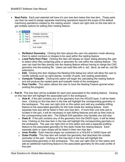
BobNEST Software User <strong>Manual</strong>Nest Parts: Each part selected will have it's own tree item below this tree item. These partscan then be used to assign separate machining operations beyond the scope of the defaultmachining operations created by the nesting wizard. Users can right click on this tree item toget multiple options for editing their nesting feature:o Re/Select Geometry: Clicking this item places the user into selection mode allowingthem to select contours or shapes to be used within the nesting feature.o Load Parts from Files: Clicking this item will display an Open dialog allowing the userto select other files containing parts or geometry for use within the nesting feature. Theuser can load the files directly into the nesting feature without having to merge the CADgeometry into the existing file. Users can load files with a .dxf, .bbcd, as well as .cad fileextensions.o Edit: Clicking this item displays the <strong>Nesting</strong> Edit dialog box which will allow the user tomodify settings such as rapid planes, number of parts, and nesting parameters.o Compute Toolpath: Clicking this option will begin the calculating the nesting featureand will produce the nested parts and toolpath inside of the workspace.o Post Yes/No: This option allows the user to have the <strong>Nesting</strong> Feature ignored whenposting the program.Part #: This tree item will be available for each part associated to the nesting feature. Clickingon this tree item will highlight the associated part in the workspace.o Hole #: If the part contains any of the geometry from the HOLES layer, it will be listedhere. Clicking on this tree item in the tree will highlight the corresponding geometry inthe workspace. The user can right click on this option and add any available drillingfeature to the associated geometry for this hole inside the nesting feature. Eachseparate hole size will be listed in their own tree item. If more than one hole size islocated in the part, it will be necessary to add drilling features and set up their tools tothe corresponding hole item. The Default Drill operation only handles one drill size.o Dado #: If the part contains any of the geometry from the DADO layer, it will be listedhere. Clicking on this tree item in the tree will highlight the corresponding geometry inthe workspace. The user can right click on this option and add a separate profilingfeature to the associated geometry for this dado inside the nesting feature. Eachseparate dado or open shape will be listed in their own tree item.o Inner Profile: Each internal shape not contained on a HOLES or DADO layer willo Outer Profile: This tree item will contain the geometry that describes the outsideperimeter of the part. Clicking on this tree item in the tree will highlight thecorresponding geometry in the workspace. The user can right click on this option andadd an additional machining feature to the associated geometry for the outer profile ofthis part.Real Solutions for Global Manufacturing 23