
You also want an ePaper? Increase the reach of your titles
YUMPU automatically turns print PDFs into web optimized ePapers that Google loves.
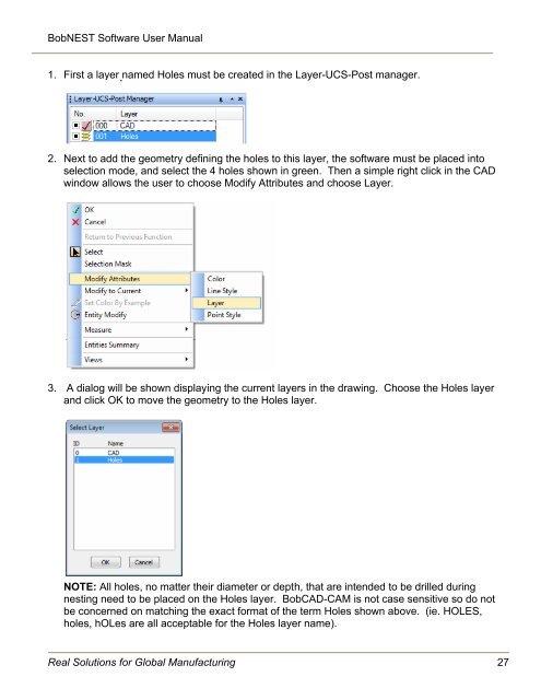
BobNEST Software User <strong>Manual</strong>1. First a layer named Holes must be created in the Layer-UCS-Post manager.2. Next to add the geometry defining the holes to this layer, the software must be placed intoselection mode, and select the 4 holes shown in green. Then a simple right click in the CADwindow allows the user to choose Modify Attributes and choose Layer.3. A dialog will be shown displaying the current layers in the drawing. Choose the Holes layerand click OK to move the geometry to the Holes layer.NOTE: All holes, no matter their diameter or depth, that are intended to be drilled duringnesting need to be placed on the Holes layer. <strong>BobCAD</strong>-<strong>CAM</strong> is not case sensitive so do notbe concerned on matching the exact format of the term Holes shown above. (ie. HOLES,holes, hOLes are all acceptable for the Holes layer name).Real Solutions for Global Manufacturing 27