BRC Series System Guide - Sony
BRC Series System Guide - Sony
BRC Series System Guide - Sony
- No tags were found...

Create successful ePaper yourself
Turn your PDF publications into a flip-book with our unique Google optimized e-Paper software.
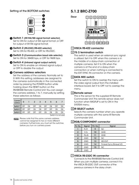
OFFOFFONONRSetting of the BOTTOM switches1234ON12345.1.2 <strong>BRC</strong>-Z700Rear1 2 3 4 5 61234ON51 2 3 4 5 6 7 8 9VISCA RS-422DATA MIX751 2 3IR SELECTRGB/COMPONENTIN VISCA RS-232C OUT EXT SYNC IN VIDEO S VIDEODC IN 12V12345Switch 1 (59.94i/50i signal format selector)Set to ON for output of 50i signal format, or OFFfor output of 59.94i signal format.Switch 2 (RS-232C/RS-422 selector)Set to ON for RS-422, or OFF for RS-232C.Switch 3 (Communication baud rate selector)Set to ON for 38400 bps, or OFF for 9600 bps.Switch 4 (Infrared signal output switch)Set to ON to enable an infrared signal output,or OFF to disable the output.Camera address selectorsSet the address of the camera. Normally set to0. With this setting, addresses are assigned tothe cameras automatically in the connectedorder by pressing the POWER button whileholding down the RESET button on theRM-BR300 Remote Control Unit. You can assignthe camera address, 1 to 7, manually by settingthese selectors as follows:Camera0 1 2 3 4 5 6 7addressSwitch 1 OFF ON OFF ON OFF ON OFF ONSwitch 2 OFF OFF ON ON OFF OFF ON ONSwitch 3 OFF OFF OFF OFF ON ON ON ONSwitch 4 is not used.NotePlease note that the same camera addresscannot be assigned to two or more differentcameras. Furthermore, you must set the switchesbefore you turn on camera power.1 VISCA RS-422 connector2 75 Ω termination switchThis switch is used when an external sync signalis utilized. Set it to OFF when this camera is inthe middle of a daisy-chain connection ofmultiple cameras. Set it to ON when thecamera is at the end of a daisy-chainconnection or when nothing is connected tothe EXT SYNC IN connector on the camera.34567 8 9 10 11 12 13DATA MIX switchSet the switch to ON to overlap the menu withthe video signal output from the installedinterface board. Set it to OFF not to overlap themenu.Remote sensorThis is the sensor for the supplied IR RemoteCommander Unit. This remote sensor does notfunction when IMGFLIP is set to ON in theSYSTEM menu.IR SELECT switchSelects the camera number when you operatemultiple cameras with the same IR RemoteCommander Unit.RGB/COMPONENT connectorPin No. Signal Pin No. Signal1 Pr/R 9 NC2 Y/G 10 GND3 Pb/B 11 GND4 GND 12 NC5 GND 13 HD-OUT6 GND 14 Tri-level Sync/Bi-level VD7 GND 15 NC8 GND7 VISCA RS-232C IN connectorConnects to the RM-BR300 Remote Control Unit.When you join multiple cameras, connect it tothe VISCA RS-232C OUT connector of theprevious camera in the daisy chain.14 Location and Function of Parts