BRC Series System Guide - Sony
BRC Series System Guide - Sony
BRC Series System Guide - Sony
- No tags were found...

Create successful ePaper yourself
Turn your PDF publications into a flip-book with our unique Google optimized e-Paper software.
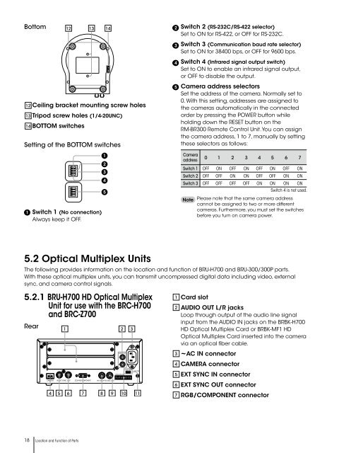
Bottom12 13 142Switch 2 (RS-232C/RS-422 selector)Set to ON for RS-422, or OFF for RS-232C.3Switch 3 (Communication baud rate selector)Set to ON for 38400 bps, or OFF for 9600 bps.4Switch 4 (Infrared signal output switch)Set to ON to enable an infrared signal output,or OFF to disable the output.121314Ceiling bracket mounting screw holesTripod screw holes (1/4-20UNC)BOTTOM switchesSetting of the BOTTOM switches5Camera address selectorsSet the address of the camera. Normally set to0. With this setting, addresses are assigned tothe cameras automatically in the connectedorder by pressing the POWER button whileholding down the RESET button on theRM-BR300 Remote Control Unit. You can assignthe camera address, 1 to 7, manually by settingthese selectors as follows:1Switch 1 (No connection)Always keep it OFF.12341234ONON12345Camera0 1 2 3 4 5 6 7addressSwitch 1 OFF ON OFF ON OFF ON OFF ONSwitch 2 OFF OFF ON ON OFF OFF ON ONSwitch 3 OFF OFF OFF OFF ON ON ON ONSwitch 4 is not used.NotePlease note that the same camera addresscannot be assigned to two or more differentcameras. Furthermore, you must set the switchesbefore you turn on camera power.5.2 Optical Multiplex UnitsThe following provides information on the location and function of BRU-H700 and BRU-300/300P parts.With these optical multiplex units, you can transmit uncompressed digital data including video, externalsync, and camera control signals.5.2.1 BRU-H700 HD Optical MultiplexUnit for use with the <strong>BRC</strong>-H700and <strong>BRC</strong>-Z700Rear1 2 31 Card slot2 AUDIO OUT L/R jacksLoop through output of the audio line signalinput from the AUDIO IN jacks on the BRBK-H700HD Optical Multiplex Card or BRBK-MF1 HDOptical Multiplex Card inserted into the cameravia an optical fiber cable.AUDIO OUTLRFUNCTION~AC IN1 6VISCA RS-422345~AC IN connectorCAMERA connectorEXT SYNC IN connectorCAMERAIN EXT SYNC OUTRGB/COMPONENTIN VISCA RS-232C OUT6EXT SYNC OUT connector4 5 6 7 8 9 10 117RGB/COMPONENT connector18 Location and Function of Parts