Jens Janssen Diploma Thesis - Prof. Dr. Norbert Wermes ...
Jens Janssen Diploma Thesis - Prof. Dr. Norbert Wermes ...
Jens Janssen Diploma Thesis - Prof. Dr. Norbert Wermes ...
Create successful ePaper yourself
Turn your PDF publications into a flip-book with our unique Google optimized e-Paper software.
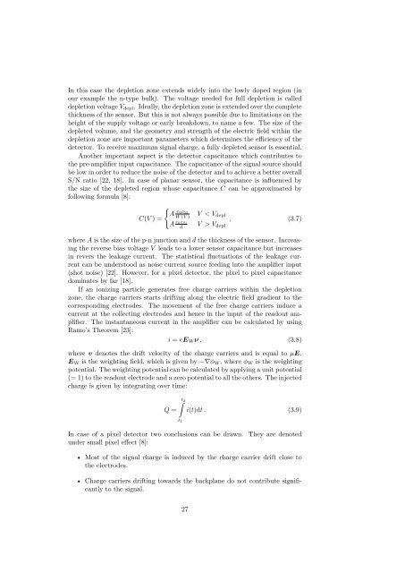
In this case the depletion zone extends widely into the lowly doped region (inour example the n-type bulk). The voltage needed for full depletion is calleddepletion voltage V depl . Ideally, the depletion zone is extended over the completethickness of the sensor. But this is not always possible due to limitations on theheight of the supply voltage or early breakdown, to name a few. The size of thedepleted volume, and the geometry and strength of the electric field within thedepletion zone are important parameters which determines the e ciency of thedetector. To receive maximum signal charge, a fully depleted sensor is essential.Another important aspect is the detector capacitance which contributes tothe pre-amplifier input capacitance. The capacitance of the signal source shouldbe low in order to reduce the noise of the detector and to achieve a better overallS/N ratio [22, 18]. In case of planar sensor, the capacitance is influenced bythe size of the depleted region whose capacitance C can be approximated byfollowing formula [8]:C(V )=IAÁ 0Á SiW (V )V < V deplA Á0Á , (3.7)SidV > V deplwhere A is the size of the p-n junction and d the thickness of the sensor. Increasingthe reverse bias voltage V leads to a lower sensor capacitance but increasesin revers the leakage current. The statistical fluctuations of the leakage currentcan be understood as noise current source feeding into the amplifier input(shot noise) [22]. However, for a pixel detector, the pixel to pixel capacitancedominates by far [18].If an ionizing particle generates free charge carriers within the depletionzone, the charge carriers starts drifting along the electric field gradient to thecorresponding electrodes. The movement of the free charge carriers induce acurrent at the collecting electrodes and hence in the input of the readout amplifier.The instantaneous current in the amplifier can be calculated by usingRamo’s Theorem [23]:i = eE W ‹ , (3.8)where v denotes the drift velocity of the charge carriers and is equal to µE.E W is the weighting field, which is given by ≠Ò„ W ,where„ W is the weightingpotential. The weighting potential can be calculated by applying a unit potential(= 1) to the readout electrode and a zero potential to all the others. The injectedcharge is given by integrating over time:Q =ˆt 2t 1i(t)dt . (3.9)In case of a pixel detector two conclusions can be drawn. They are denotedunder small pixel e ect [8]:• Most of the signal charge is induced by the charge carrier drift close tothe electrodes.• Charge carriers drifting towards the backplane do not contribute significantlyto the signal.27


