Jens Janssen Diploma Thesis - Prof. Dr. Norbert Wermes ...
Jens Janssen Diploma Thesis - Prof. Dr. Norbert Wermes ...
Jens Janssen Diploma Thesis - Prof. Dr. Norbert Wermes ...

You also want an ePaper? Increase the reach of your titles
YUMPU automatically turns print PDFs into web optimized ePapers that Google loves.
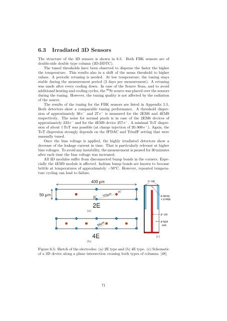
6.3 Irradiated 3D SensorsThe structure of the 3D sensors is shown in 6.5. Both FBK sensors are ofdouble-side double type column (3D-DDTC).The tuned thresholds have been observed to disperse the faster the higherthe temperature. This results also in a shift of the mean threshold to highervalues. A periodic retuning is needed. At low temperature, the tuning staysstable during the measurement period (2 days per measurement). A retuningwas made after every cooling down. In case of the Source Scan, and to avoidadditional heating and cooling cycles, the 90 Sr source was placed over the sensorsduring the tuning. However, the tuning quality is not a ected by the radiationof the source.The results of the tuning for the FBK sensors are listed in Appendix 5.5.Both detectors show a comparable tuning performance. A threshold dispersionof approximately 30 e ≠ and 27 e ≠ is measured for the 2EM6 and 4EM9respectively. The noise for normal pixels is in case of the 2EM6 devices ofapproximately 233 e ≠ and for the 4EM9 device 257 e ≠ . A minimal ToT dispersionof about 1 ToT was possible (at charge injection of 20, 000 e ≠ ). Again, theToT dispersion strongly depends on the IFDAC and TrimIF setting that weremanually tuned.Once the bias voltage is applied, the highly irradiated detectors show adecrease of the leakage current in time. That is particularly relevant at higherbias voltages. To avoid any instability, the measurement is paused for 30 minutesafter each time the bias voltage was increased.All 3D modules su er from disconnected bump bonds in the corners. Especiallythe 4EM9 module is a ected. Indium bump bonds are known to becomebrittle at temperatures of approximately ≠50°C. However, repeated temperaturecycling can lead to failure.(a)(b)(c)Figure 6.5: Sketch of the electrodes: (a) 2E type and (b) 4E type. (c) Schematicof a 3D device along a plane intersection crossing both types of columns. [48]71