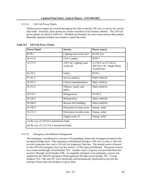
8.5.2.8. 120-Volt Power PanelsUpdated Final Safety Analysis Report - (STS-004-002)Thirteen power panels are located throughout the ship to furnish 120-volt, a-c power for variousship loads. Generally, these panels are surface-mounted circuit breaker cabinets. The 120-voltpower panels are listed in Table 8-5. Molded-case breakers at source buses protect these panels.Manually operated molded-case breakers control the loads.Table 8-5120-Volt Power PanelsPower Panel Service Power sourceB-99-1 Lighting load center fwd. B-<strong>10</strong>2-1(a)B-115-2 Crew’s pantry B-99-1A-177-2120 VAC Lighting loadcenter aftB-125-l Galley B-99-1A-176-4 via 37.5 KVA480/120 VAC, Single PhaseTransformerP-141-2 Service pantries Main swbd.(b)D-143-1 Critical instrumentation Main swbd.(a)B-135-2Officers’ pantry andgalleyMain swbd.(b)D-118-1 Refrigeration H-120-2H-120-2 Refrigeration Main swbd.(b)B-<strong>10</strong>8-4 Reactor fuel handling Main swbd.(b)N-130-2 Electronics in chart room Emerg. swbd.N-131-1 Electronics in radio room Emerg. swbd,(a) By way <strong>of</strong> 150 kVA transformer bank.Engine room 1C(b) By way <strong>of</strong> 112.5 kVA transformer bank.Emerg. swbd.8.5.2.9. Emergency Switchboard ArrangementThe emergency switchboard is a section <strong>of</strong> freestanding, metal-clad switchgear located on thenavigation bridge deck. This emergency switchboard includes a 450-volt, a-c bus, a 120-volt,ac-to-dc temporary bus, and a 120-volt, d-c temporary final bus. The normal source <strong>of</strong> powerfor the 450-volt emergency bus was bus section 1 <strong>of</strong> the main switchboard. This power sourcewas connected through circuit breaker 52A. Another source <strong>of</strong> power was provided from bussection 2 through circuit breaker 52B. As originally designed, in an emergency, power wassupplied by the 500 kW emergency diesel generator through circuit breaker 52C. Circuitbreakers 52A, 52B, and 52C were electrically and mechanically interlocked to prevent theclosing <strong>of</strong> more than one breaker at a given time.Rev. VI 86
Updated Final Safety Analysis Report - (STS-004-002)The 120-volt, a-c final bus is fed from the Shore Power Switchboard after modifications in20<strong>10</strong>. Originally, the 120-volt, a-c final bus was fed from the emergency 450-volt bus throughone <strong>of</strong> the two 112.5 kVA transformer banks. An automatic bus transfer switch providedchangeover capability.The 120-volt, d-c battery bus was fed from a 120-volt emergency battery which has beendeactivated, disabled and performs no active function. The 120-volt, ac-to-dc temporary buswas fed normally from the 120-volt, a-c final bus, or, in case <strong>of</strong> emergency, it could have beenfed from the battery bus by an automatic transfer switch. The 120-volt, d-c temporary final buswas fed normally from the 450-volt emergency bus through one <strong>of</strong> two 7.5 kW rectifiers orfrom the battery bus through an automatic transfer switch. Protection and control <strong>of</strong> theemergency switchboard were provided by the generator breaker and the various feeder breakers.8.5.2.<strong>10</strong>. Emergency Switchboard OperationEmergency switchboard operation consisted <strong>of</strong> setting the board up for normal and emergencypower arrangements. The 450-volt section, the 120-volt, a-c section, and the 120-volt, d-csection provided continuous distribution <strong>of</strong> power to a number <strong>of</strong> normally operating auxiliarysystems. The power under normal operating conditions came from either section 1 or 2 <strong>of</strong> themain switchboard through individual manual circuit breakers on the main switchboard sections.This power input to the 450-volt section <strong>of</strong> the emergency switchboard was by way <strong>of</strong> manualautomaticcircuit breakers in series with the main switchboard breakers. A selector switch onthe emergency board permited selecting either <strong>of</strong> the inputs as the preferred source <strong>of</strong> power.An automatic circuit breaker control system provided capability to transfer the input breakersfrom either section 1 or 2 <strong>of</strong> the main switchboard or, if conditions warranted, from theemergency diesel generator output to the 450-volt section. The transfer function could beinitiated on demand or on failure <strong>of</strong> the selected input breaker to supply the required voltage. Ifone main board input failed, the load shifted to the alternate automatically. If conditions werestill not satisfactory, the emergency diesel generator would have started and immediately closedin on the 450-volt, three-phase section.Emergency power supply status lights were located at the main and emergency switchboards toindicate the operational readiness <strong>of</strong> the emergency diesel generator and the automatic circuitbreaker control system. Additionally, a failure-to-start alarm on the main switchboard wouldhave alerted the operators to the presence <strong>of</strong> this condition at the normally unmannedemergency switchboard.As originally designed, the emergency diesel generator could not be operated in parallel witheither <strong>of</strong> the SSTGs, ADGs or shore power, but it could be fed back to the main switchboard.The emergency batteries were charged through a battery charger mounted on the emergencyswitchboard. A trickle charge was normal for the unit, and a high charge commenced if theoutput voltage dropped as a result <strong>of</strong> a load demand.8.6 Auxiliary Engine Room Systems8.6.1 Instrument Air SystemAll <strong>of</strong> the instrument air system equipment (including the main throttle assembly, high- and lowpressureturbines and main engine lubrication) is deactivated, disabled and performs no activefunction.Rev. VI 87