10 CFR 50.71(e) - Maritime Administration - U.S. Department of ...
10 CFR 50.71(e) - Maritime Administration - U.S. Department of ...
10 CFR 50.71(e) - Maritime Administration - U.S. Department of ...
Create successful ePaper yourself
Turn your PDF publications into a flip-book with our unique Google optimized e-Paper software.
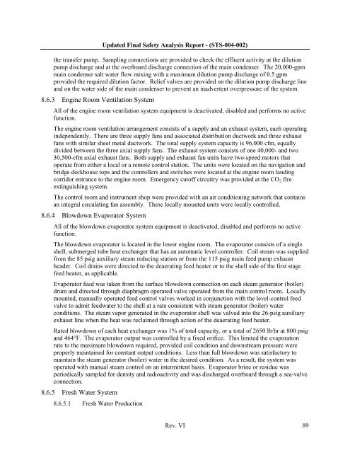
Updated Final Safety Analysis Report - (STS-004-002)the transfer pump. Sampling connections are provided to check the effluent activity at the dilutionpump discharge and at the overboard discharge connection <strong>of</strong> the main condenser. The 20,000-gpmmain condenser salt water flow mixing with a maximum dilution pump discharge <strong>of</strong> 0.5 gpmprovided the required dilution factor. Relief valves are provided on the dilution pump discharge lineand on the water side <strong>of</strong> the main condenser to prevent an inadvertent overpressure <strong>of</strong> the system.8.6.3 Engine Room Ventilation SystemAll <strong>of</strong> the engine room ventilation system equipment is deactivated, disabled and performs no activefunction.The engine room ventilation arrangement consists <strong>of</strong> a supply and an exhaust system, each operatingindependently. There are three supply fans and associated distribution ductwork and three exhaustfans with similar sheet metal ductwork. The total supply system capacity is 96,000 cfm, equallydivided between the three axial supply fans. The exhaust system consists <strong>of</strong> one 40,000- and two30,500-cfm axial exhaust fans. Both supply and exhaust fan units have two-speed motors thatoperate from either a local or a remote control station. The units were located on the navigation andbridge deckhouse tops and the controllers and switches were located at the engine room landingcorridor entrance to the engine room. Emergency cut<strong>of</strong>f circuitry was provided at the CO 2 fireextinguishing system.The control room and instrument shop were provided with an air conditioning network that containsan integral circulating fan assembly. These locally mounted units were locally controlled.8.6.4 Blowdown Evaporator SystemAll <strong>of</strong> the blowdown evaporator system equipment is deactivated, disabled and performs no activefunction.The blowdown evaporator is located in the lower engine room. The evaporator consists <strong>of</strong> a singleshell, submerged tube heat exchanger that has an automatic level controller. Coil steam was suppliedfrom the 85 psig auxiliary steam reducing station or from the 115 psig main feed pump exhaustheader. Coil drains were directed to the deaerating feed heater or to the shell side <strong>of</strong> the first stagefeed heater, as applicable.Evaporator feed was taken from the surface blowdown connection on each steam generator (boiler)drum and directed through diaphragm operated valve operated from the main control room. Locallymounted, manually operated feed control valves worked in conjunction with the level-control feedvalve to admit feedwater to the shell at a rate consistent with steam generator (boiler) waterconditions. The steam vapor generated in the evaporator shell was valved into the 26-psig auxiliaryexhaust line when the heat was reclaimed through action <strong>of</strong> the deaerating feed heater.Rated blowdown <strong>of</strong> each heat exchanger was 1% <strong>of</strong> total capacity, or a total <strong>of</strong> 2650 lb/hr at 800 psigand 464°F. The evaporator output was controlled by a fixed orifice. This limited the evaporationrate to the maximum blowdown required, provided coil condition and downstream pressure wereproperly maintained for constant output conditions. Less than full blowdown was satisfactory tomaintain the steam generator (boiler) water in the desired condition. As a result, the system wasoperated with manual steam control on an intermittent basis. Evaporator brine or residue wasperiodically sampled for density and radioactivity and was discharged overboard through a sea-valveconnection.8.6.5 Fresh Water System8.6.5.1 Fresh Water ProductionRev. VI 89


