10 CFR 50.71(e) - Maritime Administration - U.S. Department of ...
10 CFR 50.71(e) - Maritime Administration - U.S. Department of ...
10 CFR 50.71(e) - Maritime Administration - U.S. Department of ...
You also want an ePaper? Increase the reach of your titles
YUMPU automatically turns print PDFs into web optimized ePapers that Google loves.
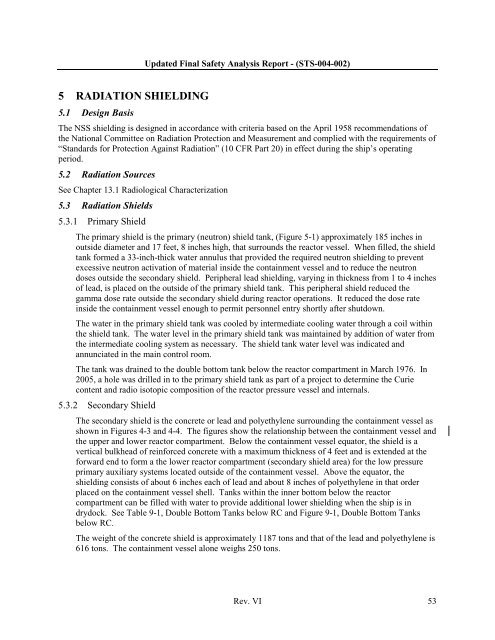
Updated Final Safety Analysis Report - (STS-004-002)5 RADIATION SHIELDING5.1 Design BasisThe NSS shielding is designed in accordance with criteria based on the April 1958 recommendations <strong>of</strong>the National Committee on Radiation Protection and Measurement and complied with the requirements <strong>of</strong>“Standards for Protection Against Radiation” (<strong>10</strong> <strong>CFR</strong> Part 20) in effect during the ship’s operatingperiod.5.2 Radiation SourcesSee Chapter 13.1 Radiological Characterization5.3 Radiation Shields5.3.1 Primary ShieldThe primary shield is the primary (neutron) shield tank, (Figure 5-1) approximately 185 inches inoutside diameter and 17 feet, 8 inches high, that surrounds the reactor vessel. When filled, the shieldtank formed a 33-inch-thick water annulus that provided the required neutron shielding to preventexcessive neutron activation <strong>of</strong> material inside the containment vessel and to reduce the neutrondoses outside the secondary shield. Peripheral lead shielding, varying in thickness from 1 to 4 inches<strong>of</strong> lead, is placed on the outside <strong>of</strong> the primary shield tank. This peripheral shield reduced thegamma dose rate outside the secondary shield during reactor operations. It reduced the dose rateinside the containment vessel enough to permit personnel entry shortly after shutdown.The water in the primary shield tank was cooled by intermediate cooling water through a coil withinthe shield tank. The water level in the primary shield tank was maintained by addition <strong>of</strong> water fromthe intermediate cooling system as necessary. The shield tank water level was indicated andannunciated in the main control room.The tank was drained to the double bottom tank below the reactor compartment in March 1976. In2005, a hole was drilled in to the primary shield tank as part <strong>of</strong> a project to determine the Curiecontent and radio isotopic composition <strong>of</strong> the reactor pressure vessel and internals.5.3.2 Secondary ShieldThe secondary shield is the concrete or lead and polyethylene surrounding the containment vessel asshown in Figures 4-3 and 4-4. The figures show the relationship between the containment vessel andthe upper and lower reactor compartment. Below the containment vessel equator, the shield is avertical bulkhead <strong>of</strong> reinforced concrete with a maximum thickness <strong>of</strong> 4 feet and is extended at theforward end to form a the lower reactor compartment (secondary shield area) for the low pressureprimary auxiliary systems located outside <strong>of</strong> the containment vessel. Above the equator, theshielding consists <strong>of</strong> about 6 inches each <strong>of</strong> lead and about 8 inches <strong>of</strong> polyethylene in that orderplaced on the containment vessel shell. Tanks within the inner bottom below the reactorcompartment can be filled with water to provide additional lower shielding when the ship is indrydock. See Table 9-1, Double Bottom Tanks below RC and Figure 9-1, Double Bottom Tanksbelow RC.The weight <strong>of</strong> the concrete shield is approximately 1187 tons and that <strong>of</strong> the lead and polyethylene is616 tons. The containment vessel alone weighs 250 tons.Rev. VI 53


