10 CFR 50.71(e) - Maritime Administration - U.S. Department of ...
10 CFR 50.71(e) - Maritime Administration - U.S. Department of ...
10 CFR 50.71(e) - Maritime Administration - U.S. Department of ...
Create successful ePaper yourself
Turn your PDF publications into a flip-book with our unique Google optimized e-Paper software.
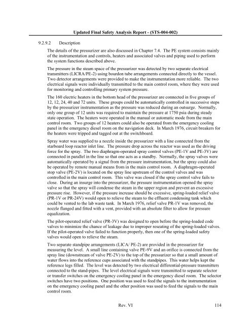
9.2.9.2 DescriptionUpdated Final Safety Analysis Report - (STS-004-002)The details <strong>of</strong> the pressurizer are also discussed in Chapter 7.4. The PE system consists mainly<strong>of</strong> the instrumentation and controls, heaters and associated valves and piping used to performthe system functions described above.The pressure in the steam space <strong>of</strong> the pressurizer was detected by two separate electricaltransmitters (LICRA/PE-2) using bourdon tube arrangements connected directly to the vessel.Two detector arrangements were provided to make the instrumentation more reliable. The twoelectrical signals were individually transmitted to the main control room, where they were usedfor monitoring and controlling primary system pressure.The 160 electric heaters in the bottom head <strong>of</strong> the pressurizer are connected in five groups <strong>of</strong>12, 12, 24, 40 and 72 units. These groups could be automatically controlled in successive stepsby the pressurizer instrumentation as the pressure was reduced during an outsurge. Normally,only one group <strong>of</strong> 12 units was required to maintain the pressure at 1750 psia during steadystate operation. The heaters were operated in the manual or automatic mode from the maincontrol room. Two groups <strong>of</strong> 12 heaters could also be operated from the emergency coolingpanel in the emergency diesel room on the navigation deck. In March 1976, circuit breakers forthe heaters were tripped and tagged out at the switchboard.Spray water was supplied to a nozzle inside the pressurizer with a line connected from thestarboard loop reactor inlet line. The pressure drop across the reactor was used as the drivingforce for the spray. The two diaphragm-operated spray control valves (PE-1V and PE-3V) areconnected in parallel in the line so that one acts as a standby. Normally, the spray valves wereautomatically operated by a signal from the pressure instrumentation, but the spray could alsobe operated by remote manual means from in the main control room. A diaphragm-operatedstop valve (PE-2V) is located on the spray line upstream <strong>of</strong> the control valves and wascontrolled in the main control room. This valve was closed if the spray control valve fails toclose. During an insurge into the pressurizer, the pressure instrumentation opened the sprayvalve so that the spray will condense the steam in the upper region and prevent an excessivepressure rise. However, if the pressure increase should be excessive, spring-loaded relief valve(PR-1V or PR-24V) would open to relieve the steam to the effluent condensing tank whichcould be vented to the lab waste tank. In March 1976, relief valve PR-1V was removed, thenozzle flanged and fitted with a vent, provided with an absolute filter to allow for pressureequalization.The pilot-operated relief valve (PR-3V) was designed to open before the spring-loaded codevalves to minimize the chance <strong>of</strong> leakage due to improper reseating <strong>of</strong> the spring-loaded valves.If the pilot-operated valve failed to function properly, then one <strong>of</strong> the spring-loaded safetyvalves would open to relieve the steam.Two separate standpipe arrangements (LICA/ PE-2) are provided in the pressurizer formeasuring the level. A small line containing valve PE-9V and an orifice is connected from thespray line (downstream <strong>of</strong> valve PE-2V) to the top <strong>of</strong> the pressurizer so that a small amount <strong>of</strong>water flows into the reference cups associated with the standpipes. This water helps kept thereference legs filled. The level was detected by two electrical differential-pressure transmittersconnected to the stand-pipes. The level electrical signals were transmitted to separate selectoror transfer switches on the emergency cooling panel in the emergency diesel room. The selectorswitches have two positions. One position was used to feed the signals to the instrumentationon the emergency cooling panel and the other position was used to feed the signals to the maincontrol room.Rev. VI 114


