10 CFR 50.71(e) - Maritime Administration - U.S. Department of ...
10 CFR 50.71(e) - Maritime Administration - U.S. Department of ...
10 CFR 50.71(e) - Maritime Administration - U.S. Department of ...
Create successful ePaper yourself
Turn your PDF publications into a flip-book with our unique Google optimized e-Paper software.
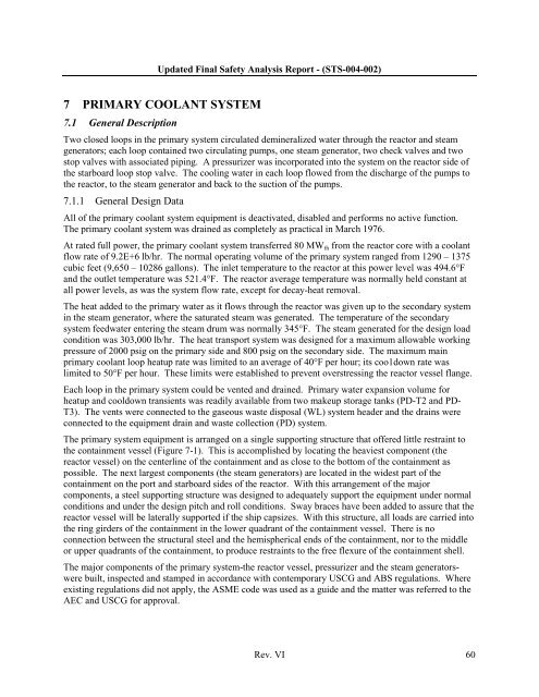
Updated Final Safety Analysis Report - (STS-004-002)7 PRIMARY COOLANT SYSTEM7.1 General DescriptionTwo closed loops in the primary system circulated demineralized water through the reactor and steamgenerators; each loop contained two circulating pumps, one steam generator, two check valves and twostop valves with associated piping. A pressurizer was incorporated into the system on the reactor side <strong>of</strong>the starboard loop stop valve. The cooling water in each loop flowed from the discharge <strong>of</strong> the pumps tothe reactor, to the steam generator and back to the suction <strong>of</strong> the pumps.7.1.1 General Design DataAll <strong>of</strong> the primary coolant system equipment is deactivated, disabled and performs no active function.The primary coolant system was drained as completely as practical in March 1976.At rated full power, the primary coolant system transferred 80 MW th from the reactor core with a coolantflow rate <strong>of</strong> 9.2E+6 lb/hr. The normal operating volume <strong>of</strong> the primary system ranged from 1290 – 1375cubic feet (9,650 – <strong>10</strong>286 gallons). The inlet temperature to the reactor at this power level was 494.6°Fand the outlet temperature was 521.4°F. The reactor average temperature was normally held constant atall power levels, as was the system flow rate, except for decay-heat removal.The heat added to the primary water as it flows through the reactor was given up to the secondary systemin the steam generator, where the saturated steam was generated. The temperature <strong>of</strong> the secondarysystem feedwater entering the steam drum was normally 345°F. The steam generated for the design loadcondition was 303,000 lb/hr. The heat transport system was designed for a maximum allowable workingpressure <strong>of</strong> 2000 psig on the primary side and 800 psig on the secondary side. The maximum mainprimary coolant loop heatup rate was limited to an average <strong>of</strong> 40°F per hour; its coo1down rate waslimited to 50°F per hour. These limits were established to prevent overstressing the reactor vessel flange.Each loop in the primary system could be vented and drained. Primary water expansion volume forheatup and cooldown transients was readily available from two makeup storage tanks (PD-T2 and PD-T3). The vents were connected to the gaseous waste disposal (WL) system header and the drains wereconnected to the equipment drain and waste collection (PD) system.The primary system equipment is arranged on a single supporting structure that <strong>of</strong>fered little restraint tothe containment vessel (Figure 7-1). This is accomplished by locating the heaviest component (thereactor vessel) on the centerline <strong>of</strong> the containment and as close to the bottom <strong>of</strong> the containment aspossible. The next largest components (the steam generators) are located in the widest part <strong>of</strong> thecontainment on the port and starboard sides <strong>of</strong> the reactor. With this arrangement <strong>of</strong> the majorcomponents, a steel supporting structure was designed to adequately support the equipment under normalconditions and under the design pitch and roll conditions. Sway braces have been added to assure that thereactor vessel will be laterally supported if the ship capsizes. With this structure, all loads are carried intothe ring girders <strong>of</strong> the containment in the lower quadrant <strong>of</strong> the containment vessel. There is noconnection between the structural steel and the hemispherical ends <strong>of</strong> the containment, nor to the middleor upper quadrants <strong>of</strong> the containment, to produce restraints to the free flexure <strong>of</strong> the containment shell.The major components <strong>of</strong> the primary system-the reactor vessel, pressurizer and the steam generatorswerebuilt, inspected and stamped in accordance with contemporary USCG and ABS regulations. Whereexisting regulations did not apply, the ASME code was used as a guide and the matter was referred to theAEC and USCG for approval.Rev. VI 60


