

10 CFR 50.71(e) - Maritime Administration - U.S. Department of ...
10 CFR 50.71(e) - Maritime Administration - U.S. Department of ...
10 CFR 50.71(e) - Maritime Administration - U.S. Department of ...

You also want an ePaper? Increase the reach of your titles
YUMPU automatically turns print PDFs into web optimized ePapers that Google loves.
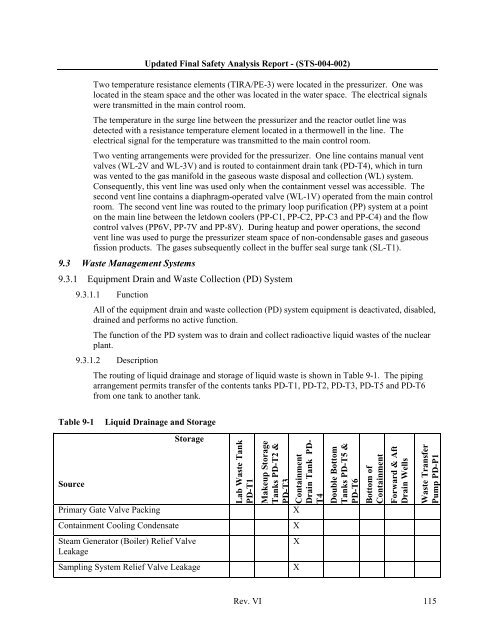
Updated Final Safety Analysis Report - (STS-004-002)Two temperature resistance elements (TIRA/PE-3) were located in the pressurizer. One waslocated in the steam space and the other was located in the water space. The electrical signalswere transmitted in the main control room.The temperature in the surge line between the pressurizer and the reactor outlet line wasdetected with a resistance temperature element located in a thermowell in the line. Theelectrical signal for the temperature was transmitted to the main control room.Two venting arrangements were provided for the pressurizer. One line contains manual ventvalves (WL-2V and WL-3V) and is routed to containment drain tank (PD-T4), which in turnwas vented to the gas manifold in the gaseous waste disposal and collection (WL) system.Consequently, this vent line was used only when the containment vessel was accessible. Thesecond vent line contains a diaphragm-operated valve (WL-1V) operated from the main controlroom. The second vent line was routed to the primary loop purification (PP) system at a pointon the main line between the letdown coolers (PP-C1, PP-C2, PP-C3 and PP-C4) and the flowcontrol valves (PP6V, PP-7V and PP-8V). During heatup and power operations, the secondvent line was used to purge the pressurizer steam space <strong>of</strong> non-condensable gases and gaseousfission products. The gases subsequently collect in the buffer seal surge tank (SL-T1).9.3 Waste Management Systems9.3.1 Equipment Drain and Waste Collection (PD) System9.3.1.1 FunctionAll <strong>of</strong> the equipment drain and waste collection (PD) system equipment is deactivated, disabled,drained and performs no active function.The function <strong>of</strong> the PD system was to drain and collect radioactive liquid wastes <strong>of</strong> the nuclearplant.9.3.1.2 DescriptionThe routing <strong>of</strong> liquid drainage and storage <strong>of</strong> liquid waste is shown in Table 9-1. The pipingarrangement permits transfer <strong>of</strong> the contents tanks PD-T1, PD-T2, PD-T3, PD-T5 and PD-T6from one tank to another tank.Table 9-1SourceLiquid Drainage and StoragePrimary Gate Valve PackingContainment Cooling CondensateStorageSteam Generator (Boiler) Relief ValveLeakageSampling System Relief Valve LeakageLab Waste TankPD-T1Makeup StorageTanks PD-T2 &PD-T3ContainmentDrain Tank PD-T4XXXXDouble BottomTanks PD-T5 &PD-T6Bottom <strong>of</strong>ContainmentForward & AftDrain WellsWaste TransferPump PD-P1Rev. VI 115


