- Page 1 and 2:
0U.S. Department Savannah Technical
- Page 3 and 4:
Docket No. 50-238; License NS-1; N.
- Page 5:
Ttit 1 ►'1 ltt tU.S. Department o
- Page 8:
PageNo.Rev.No.Updated Final Safety
- Page 11 and 12:
Updated Final Safety Analysis Repor
- Page 13 and 14:
Updated Final Safety Analysis Repor
- Page 15 and 16:
Updated Final Safety Analysis Repor
- Page 17 and 18:
Updated Final Safety Analysis Repor
- Page 19 and 20:
Updated Final Safety Analysis Repor
- Page 21 and 22:
Updated Final Safety Analysis Repor
- Page 23 and 24:
Updated Final Safety Analysis Repor
- Page 25 and 26:
Updated Final Safety Analysis Repor
- Page 27 and 28:
Updated Final Safety Analysis Repor
- Page 29 and 30:
Updated Final Safety Analysis Repor
- Page 31 and 32:
Updated Final Safety Analysis Repor
- Page 33 and 34: U p da te d Fi na lS af et yA n al
- Page 35 and 36: Updated Final Safety Analysis Repor
- Page 37 and 38: Updated Final Safety Analysis Repor
- Page 39 and 40: Updated Final Safety Analysis Repor
- Page 41 and 42: Updated Final Safety Analysis Repor
- Page 43 and 44: Figure 2-2General Arrangement - Inb
- Page 45 and 46: Updated Final Safety Analysis Repor
- Page 47 and 48: 3.2.3 Port Operating CriteriaUpdate
- Page 49 and 50: Updated Final Safety Analysis Repor
- Page 51 and 52: Updated Final Safety Analysis Repor
- Page 53 and 54: Updated Final Safety Analysis Repor
- Page 55 and 56: Updated Final Safety Analysis Repor
- Page 57 and 58: Updated Final Safety Analysis Repor
- Page 59 and 60: U p da te d Fi na lS af et yA n al
- Page 61 and 62: Table 4-1List of Containment Penetr
- Page 63 and 64: Table 4-1List of Containment Penetr
- Page 65 and 66: Table 4-1List of Containment Penetr
- Page 67 and 68: Table 4-1List of Containment Penetr
- Page 69 and 70: Table 4-1List of Containment Penetr
- Page 71 and 72: Updated Final Safety Analysis Repor
- Page 73 and 74: 5.3.3 Local ShieldingUpdated Final
- Page 75 and 76: Updated Final Safety Analysis Repor
- Page 77 and 78: Updated Final Safety Analysis Repor
- Page 79 and 80: 7.1.2 General Performance DataUpdat
- Page 81 and 82: 7.1.2.3 Water ChemistryUpdated Fina
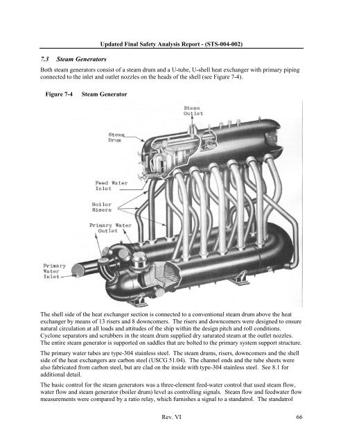
- Page 83: Updated Final Safety Analysis Repor
- Page 87 and 88: 7.5 Primary PumpsUpdated Final Safe
- Page 89 and 90: Updated Final Safety Analysis Repor
- Page 91 and 92: 8.1.3 Construction Features8.1.3.1
- Page 93 and 94: Updated Final Safety Analysis Repor
- Page 95 and 96: Updated Final Safety Analysis Repor
- Page 97 and 98: Updated Final Safety Analysis Repor
- Page 99 and 100: Figure 8-2Current Electrical Distri
- Page 101 and 102: Updated Final Safety Analysis Repor
- Page 103 and 104: Updated Final Safety Analysis Repor
- Page 105 and 106: Updated Final Safety Analysis Repor
- Page 107 and 108: Updated Final Safety Analysis Repor
- Page 109 and 110: Updated Final Safety Analysis Repor
- Page 111 and 112: Updated Final Safety Analysis Repor
- Page 113 and 114: Updated Final Safety Analysis Repor
- Page 115 and 116: 9.2.1.2 DescriptionUpdated Final Sa
- Page 117 and 118: 9.2.2 Buffer Seal (SL) System9.2.2.
- Page 119 and 120: Updated Final Safety Analysis Repor
- Page 121 and 122: Updated Final Safety Analysis Repor
- Page 123 and 124: 9.2.5.2 DescriptionUpdated Final Sa
- Page 125 and 126: 9.2.6.2 DescriptionUpdated Final Sa
- Page 127 and 128: Updated Final Safety Analysis Repor
- Page 129 and 130: Updated Final Safety Analysis Repor
- Page 131 and 132: 9.2.8 Shutdown Circulation (SC) Sys
- Page 133 and 134: Updated Final Safety Analysis Repor
- Page 135 and 136:
Updated Final Safety Analysis Repor
- Page 137 and 138:
Updated Final Safety Analysis Repor
- Page 139 and 140:
Updated Final Safety Analysis Repor
- Page 141 and 142:
10.3.3 Non-nuclear InstrumentationU
- Page 143 and 144:
Updated Final Safety Analysis Repor
- Page 145 and 146:
11.5 Quality Assurance PlanUpdated
- Page 147 and 148:
Updated Final Safety Analysis Repor
- Page 149 and 150:
Updated Final Safety Analysis Repor
- Page 151 and 152:
Updated Final Safety Analysis Repor
- Page 153 and 154:
Updated Final Safety Analysis Repor
- Page 155 and 156:
Deck/compartmentsUpdated Final Safe
- Page 157 and 158:
Updated Final Safety Analysis Repor
- Page 159 and 160:
Updated Final Safety Analysis Repor
- Page 161 and 162:
Updated Final Safety Analysis Repor
- Page 163 and 164:
Updated Final Safety Analysis Repor
- Page 165 and 166:
Updated Final Safety Analysis Repor
- Page 167 and 168:
Updated Final Safety Analysis Repor
- Page 169 and 170:
Updated Final Safety Analysis Repor