10 CFR 50.71(e) - Maritime Administration - U.S. Department of ...
10 CFR 50.71(e) - Maritime Administration - U.S. Department of ...
10 CFR 50.71(e) - Maritime Administration - U.S. Department of ...
You also want an ePaper? Increase the reach of your titles
YUMPU automatically turns print PDFs into web optimized ePapers that Google loves.
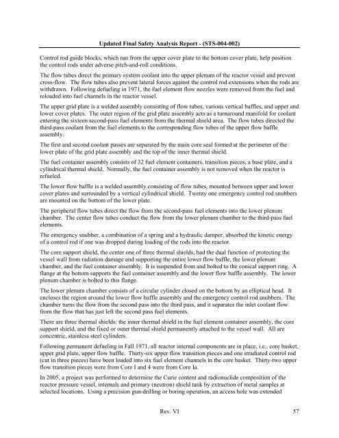
Updated Final Safety Analysis Report - (STS-004-002)Control rod guide blocks, which run from the upper cover plate to the bottom cover plate, help positionthe control rods under adverse pitch-and-roll conditions.The flow tubes direct the primary system coolant into the upper plenum <strong>of</strong> the reactor vessel and preventcross-flow. The flow tubes also prevent lateral forces against the control rod extensions when the rods arewithdrawn. Following defueling in 1971, the fuel element flow nozzles were removed from the fuel andreloaded into fuel channels in the reactor vessel.The upper grid plate is a welded assembly consisting <strong>of</strong> flow tubes, various vertical baffles, and upper andlower cover plates. The outer region <strong>of</strong> the grid plate assembly acts as a turnaround manifold for coolantentering the sixteen second-pass fuel elements from the thermal shield area. The flow tubes directed thethird-pass coolant from the fuel elements to the corresponding flow tubes <strong>of</strong> the upper flow baffleassembly.The first and second coolant passes are separated by the main core seal formed at the perimeter <strong>of</strong> thelower plate <strong>of</strong> the grid plate assembly and the top <strong>of</strong> the inner thermal shield.The fuel container assembly consists <strong>of</strong> 32 fuel element containers, transition pieces, a base plate, and acylindrical thermal shield. Normally, the fuel container assembly is not removed when the reactor isrefueled.The lower flow baffle is a welded assembly consisting <strong>of</strong> flow tubes, mounted between upper and lowercover plates and surrounded by a vertical cylindrical shield. Twenty one emergency control rod snubbersare mounted on the bottom <strong>of</strong> the lower plate.The peripheral flow tubes direct the flow from the second-pass fuel elements into the lower plenumchamber. The center flow tubes conduct the flow from the lower plenum chamber to the third-pass fuelelements.The emergency snubber, a combination <strong>of</strong> a spring and a hydraulic damper, absorbed the kinetic energy<strong>of</strong> a control rod if one was dropped during loading <strong>of</strong> the rods into the reactor.The core support shield, the center one <strong>of</strong> three thermal shields, had the dual function <strong>of</strong> protecting thevessel wall from radiation damage and supporting the entire lower flow baffle, the lower plenumchamber, and the fuel container assembly. It is suspended from and bolted to the conical support ring. Aflange at the bottom supports the fuel container assembly and the lower flow baffle assembly. The lowerplenum chamber is bolted to this flange.The lower plenum chamber consists <strong>of</strong> a circular cylinder closed on the bottom by an elliptical head. Itencloses the region around the lower flow baffle assembly and the emergency control rod snubbers. Thechamber turns the flow from the second pass into the third pass, and it separates the inlet coolant flowfrom the flow that has just left the second pass fuel elements.There are three thermal shields: the inner thermal shield in the fuel element container assembly, the coresupport shield, and the fixed or outer thermal shield permanently attached to the vessel wall. All areconcentric, stainless steel cylinders.Following permanent defueling in Fall 1971, all reactor internal components are in place, i.e., core basket,upper grid plate, upper flow baffle. Thirty-six upper flow transition pieces and one irradiated control rod(cut in three pieces) have been loaded into six fuel element channels in the core basket. Thirty-two upperflow transition pieces were from Core I and 4 were from Core Ia.In 2005, a project was performed to determine the Curie content and radionuclide composition <strong>of</strong> thereactor pressure vessel, internals and primary (neutron) shield tank by extraction <strong>of</strong> metal samples atselected locations. Using a precision gun-drilling or boring operation, an access hole was extendedRev. VI 57


